manuals.online logo
Brands
  1. Home
  2. •
  3. Brands
  4. •
  5. FARFISA INTERCOMS
  6. •
  7. Intercom System
  8. •
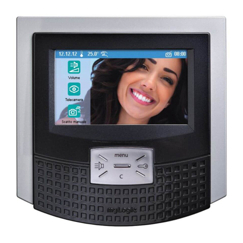
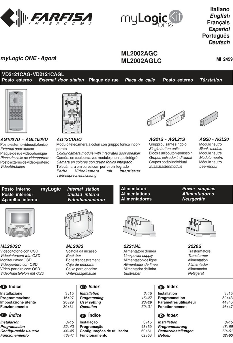
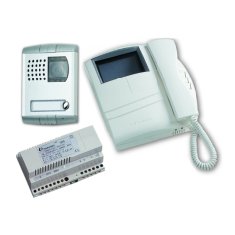
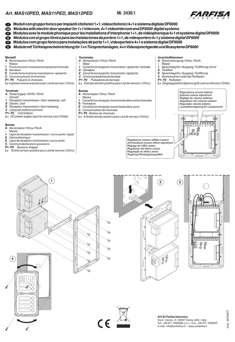
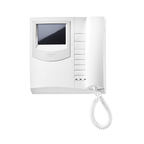
  9. FARFISA INTERCOMS myLogic ML2262PLC User manual

FARFISA INTERCOMS myLogic ML2262PLC User manual

- 1 -
Mi2447IGb
ML2262PLC
Posto esterno PROFILO external door station
myLogic - Profilo
PL72
Scatola da incasso
etelaiportamoduli
Module frame com-
pletewithback-box
VD2120CPL
Modulo telecamera a colori
congruppofonicoincorporato
Colour camera module with
integrated door speaker
CD2131PL
Modulo codificatore digita-
lecon1pulsante
Digitizer module with 1 call
button
Posto interno myLogic internal station
ML2262C
Terminale domotico con schermo touch-
screen
Touch-screen home automation terminal
ML2083
Scatola da incasso
Back-box
Alimentatori Power supplies
2221S
Alimentatoredilinea
Line power supply
2220S
Trasformatore
Transformer
IT
AVVERTENZEDISICUREZZA
Leggereattentamenteleavvertenzecontenutenelpresentemanuale
perchéfornisconoimportantiinformazioniriguardantilasicurezza
diinstallazione,usoemanutenzione.Conservarloinmodoappro-
priatoperfutureconsultazioni.
PosizionareilterminalemyLogicinambienteasciuttoelontanoda
fonti di calore o apparecchiature che producono calore e campi
magnetici.
Perlapuliziadelterminalenonusareacquaosolventichimici,ma
unpannopulito. Perlapuliziadelloschermousareilpannoallegato
alprodotto.
Questoapparecchiodeveesseredestinatosoloall’usoperilquale
èstatoconcepito.Ilcostruttorenonpuòessereconsideratorespon-
sabile per eventuali danni derivati da usi impropri, erronei ed
irragionevoli.
Nonlasciareallaportatadeibambinilepartidell’imballaggio(sac-
chettidiplastica,polistiroloespanso,ecc.).
Nonaprirel’apparecchioquandoèacceso.
L’esecuzione dell’impianto deve essere effettuato da personale
specializzatoedinconformitàconleleggivigenti.
Incasodiguasto,funzionamentoirregolareomodificaall’impianto
avvalersidipersonalespecializzato.
L’apparecchioèconformealledirettiveCEE(marchioeuropeoCE).
EN
SAFETYNOTICES
Readtheinstructionscontainedinthismanualcarefullybecause
theyprovideimportantinformationaboutsafeinstallation,useand
maintenance.Keepthismanualappropriatelyforfuturereference.
InstallyourmyLogichomeautomationterminalinadryplaceaway
fromheatsourcesordevicesthatproduceheatandmagneticfields.
Donotcleanthehomeautomationterminalwithwaterorchemical
solvents,useadryclothforcleaning.Tocleanoffthescreenuse
only the microfiber cloth which comes with the product.
Thisdevicemustbeexclusivelyoperatedforitsintendeduse.The
manufacturer cannot be held responsible for possible damage
causedbyimproper,erroneousandunreasonableuse.
Keeppackingpartsawayfromchildren(i.e.plasticbags,expanded
polystyrene, etc.).
Do not open the device when it is on.
Theinstallationmustbemadebyprofessionalsincompliancewith
theregulationsinforce.
Always refer to specialized personnel in case of breakdown,
irregularoperationorchangeintheinstallation.
ThedevicecomplieswiththeEECdirectives(CEEuropeanmark).
Italiano
English
Il manuale d'uso inizia da pagina 35 The user’s manual begins on page 35
Mi 2447IGb
- 2 -
Mi2447IGb
ML2262C.
IT
Terminale domotico vivavoce a colori con
schermo touch-screen per sistema digitale DUO
Dati tecnici
Alimentazionedirettamentedallalinea
Assorbimento: 0,2A
Schermo: 4,3"LCDtouch-screen
Standardtelevisivo: PAL
Frequenzadiriga: 15625Hz
Frequenzadiquadro: 50Hz
Bandapassante: >5MHz
Termostato: interno
Tolleranzatermostato: +/- 1°C a 20°C
Risoluzionetermostato: 0,1°C
Automaticoantigelo: +3°C
Relè: 2
Massimocaricocontattirelè: 12Vca/12÷24Vcc-1A
Temperaturadifunzionamento: 0° ÷ +50°C
Massimaumiditàammissibile: 90%RH
Morsettiere
LM/LM Ingressidilinea
A1 Ingressopositivochiamatadipiano
GN Ingressonegativochiamatadipiano
NO1 Contattonormalmenteapertodelrelé1
NC1 Contattonormalmentechiusodelrelé1
C1 Comunedelrelè1
NO2 Contattonormalmenteapertodelrelé2
NC2 Contattonormalmentechiusodelrelé2
C2 Comunedelrelé2
POSTO INTERNO INTERNAL STATION
EN
Home automation hands free device with
colourtouch-screendisplayforDUOdigitalsystem
Technical characteristics
Power supply directly from the line
Operatingcurrent: 0.2A
Screen: 4.3"LCDtouch-screen
Televisionstandard: PAL
Horizontalfrequency: 15625Hz
Verticalfrequency: 50Hz
Bandwidth: >5MHz
Thermostat: internal
Thermostattollerance: +/- 1°C to 20°C
Thermostatresolution: 0.1°C
Automaticantifreeze: +3°C
Relay: 2
Maximumloadcontacts relay: 12Vac/12÷24Vdc-1A
Operatingtemperature: 0°÷+50°C
Maximumadmissiblehumidity: 90%RH
Terminal boards
LM / LM Lineinputs
A1 Floorcall positive input
GN Floorcallnegativeinput
NO1 Normallyopencontactrelay1
NC1 Normally closed contact relay 1
C1 Commoncontactrelay1
NO2 Normallyopencontactrelay2
NC2 Normally closed contact relay 2
C2 Commoncontactrelay2
IT
Installazione
EN
Installation
1-MurarelascatoladaincassoML2083
adun'altezzadallapavimentazionedi
circa1,5metri.
-Wall-up the back box ML2083 at an
heightofabout1.5metersabovethe
floor
ML2083.
IT
Scatola da incasso per
terminaledomoticoML2262C.
EN
Back-box for ML2262C
home automation terminal.
- 3 -
Mi2447IGb
3-Effettuareicollegamentisullemorsettiere
comedaschemadarealizzare.
-Maketheconnectionsasrequiredbythe
electricdiagramtowire.
4-Reinserirelemorsettieresulterminaledomotico.
-Plug-in back the terminal blocks on the home automation
terminal.
5-Sfilarelacalottafrontaleperaccedereai4puntidifissaggiodel
terminaledomotico.
-Removethefrontalplasticframetoreachthefourfixingpoints
ofthehomeautomationterminal.
6-Fissareilterminaledomoticoallascatoladaincassoutilizzandole
4vitiforniteacorredodelprodotto.
-Fixthehomeautomationterminaltotheback-boxusingthefour
screwssuppliedwith the product.
7-Rimetterelacalottaalterminaledomotico.
-Re-insertthefrontalplasticframetothehomeautomation
terminal.
2-Toglierelemorsettieredalterminaledomotico.
-Unplugtheterminalblocksfromthehome
automationterminal.
- 4 -
Mi2447IGb
POSTO ESTERNO EXTERNAL DOOR STATION
IT
Modulo codificatore digitale
con un pulsante
Dati tecnici
Alimentazione dal modulo telecamera
VD2120CPL
Tempoazionamentoserratura: 3/6 secondi
Numerodichiamate: 128
Indirizzoprogrammatodifabbrica: 231
Dimensioni: 1modulo
Temperaturadifunzionamento: 0°÷+40°C
Massima umidità ammissibile: 90%RH
Morsetti
LP/LP fonia-dati-videoda e versogli interni
EC comando positivo per servizi ausiliari
EM comandonegativoperserviziausiliari
S1/S2 contattiaperturaserratura
CD2131PL
IT
Modulo telecamera con gruppo
fonicointegrato
Dati tecnici
Alimentazione: 13Vca±1
Assorbimento con collegamento al CD2131PL: 0,8A
Standardsegnalevideo: PAL
Illuminazioneminima: 2,5Lux
Led: 6(bianchi)
Sensore: CCD1/3" a colori
Numerodipixel: 291.000
Ottica: 3,6mm
Messa afuoco: 0,6m ÷ ∞
Brandeggioorizzontale/verticale: ±15°
Temperaturadifunzionamento: 0°÷+40°C
Massima umidità ammissibile: 90%RH
Morsetti
/ ingressoalimentazionealternata13Vca
Vingressosegnalevideodiunatelecameraesterna
supplementare(cavocoassiale)
Mmassa video (schermo coassiale)
EC comandopositivotelecamerasupplementare
EM comandonegativotelecamerasupplementare
VD2120CPL
EN
Camera with integrated audio
module
Technical data
Powersupply: 13Vac±1
Absorption with connection to encoder CD2131PL:
0.8A
Video signal standard: PAL
Minimum lighting: 2.5 Lux
LED's: 6(white)
Sensor CCD 1/3" colour
Number of pixel: 291,000
Lens: 3.6mm
Focusing: 0.6m ÷
∞
Horizontal/verticalsweep: ±15°
Operatingtemperature: 0°÷+40°C
Maximum humidity acceptable: 90% RH
Terminals
/ 13VAC voltage input
VVideo signal input of an additional external cam-
era (coaxial cable)
MVideo ground (coaxial shield)
EC Positive signal for supplementary camera
EM Negative signal for supplementary camera
EN
Digitizer module with 1 call
button
Technical features
Power supply from audio/video module
Door-opening time: 3/6seconds
Number of calls: 128
Default address: 231
Dimensions: 1 module
Operatingtemperature: 0°÷+40°C
Maximum humidity acceptable: 90% RH
Terminals
LP/LP audio-data-video to and from internal
users
EC positive signal for auxiliary services
EM negative signal for auxiliary services
S1/S2 door opening contacts
IT
Scatola da incasso e
telaiportamoduli.
EN
Module frame com-
plete with back box
PL72
- 5 -
Mi2447IGb
4
IT
Agganciarelapar-
teinferioredeltelaioalla
scatola da incasso ed
effettuareicollegamenti
elettrici.
EN
Fix lower part of
the frame to the back
box and make the
electrical connections.
IT
Fissaggio del telaio alla
scatola da incasso. Prima di
serrarelevitiallineareiltelaio.
EN
Fixing of frame to back
box. Align the frame before
tighteningthescrews.
IT
Montaggio dei moduli al telaio.
EN
Mounting modules.
6
5
3
CD2131PL
VD2120CPL
IT
Posizionare la telecamera in modo che i raggi solari o
altre fonti luminose dirette o riflesse di forte intensità non
colpiscanol’obiettivo della telecamera.
Murare la scatola da incasso della pulsantiera ad un’altezza di
circa1,65mdallapavimentazioneallatosuperioretenendoibordi
frontalia filoe a piombodell’intonaco finito.
12
IT
Muraturaepassaggiodeicavi.
EN
Flush mounting and cables
placing.
IT
Posizione delle aperture passacavo.
EN
Openings for cables.
Installazione Installation
IT
Collegareimodulitrami-
te il cavetto fornito a corredo
dell'art.CD2131PL.
EN
Connect the modules
with the cable supplied with
art. CD2131PL.
EN
Positionthecameraunitinsuchawaythat
solarrays or other direct light or intense reflec-
tions do not hit the camera lens. Placethe push-
buttonpanelbackboxataheightofabout1.65m(5'
5") from the floor keeping the front edges flush-
mounted and vertical to the finished plaster.
IT
Fissaggiodeitelaiportamoduli
al riporto superiore tramite le 2 viti
piccole fornite a corredo delle sca-
tole da incasso.
EN
Fixing of the module frames
on the upper side by the 2 small
screwsincludedinthebackboxes.
7
- 6 -
Mi2447IGb
3"
2
/
1
89
2"
16
/
15
74
5"
2
/
1
140
3"
2
/
1
89
2"
16
/
9
65
2"
8
/
1
54
Avvertenzedisicurezza
-L'installazionedelprodottodeveessereeseguitasolodaPERSONA-
LEQUALIFICATOinaccordoconleregolediinstallazionevigenti.
-Ilcollegamentoallareteelettricadeveessereeseguitoutilizzando
cavidi1mmdidiametro(AWG18).
-L’apparecchionondeveessereespostoapioggiaospruzzid’acqua.
-Uninterruttorediretebipolare,conunaseparazionedeicontattidi
almeno3mminciascunpolo,deveessereincorporatonell’installa-
zioneelettricadelsistema.
IT
ALIMENTATORE DI LINEA
Datitecnici
Alimentazionedirete: 110V÷240Vca
Frequenza: 50 ÷ 60 Hz
Potenza: 60VA
Protezioneinuscita: PTC
Sicurezza: conformeEN60065
Contenitore: DIN6moduliA
Temperaturadifunzionamento: 0°÷+40°C
Massimaumiditàammissibile: 90%RH
FissabilesuguidaDINoamurocon2tasselliadespansione
Morsetti
PRI Ingressoalimentazionedirete
LP/LP Collegamentoallalinea
IT
TRASFORMATORE
Datitecnici
Tensionedirete: 127Vo220-230Vca
Frequenza: 50 ÷ 60 Hz
Potenza: 22VA
Tensioned’uscita: 13Vca±1
Correntemassima: 1A
Protezioneinuscita: PTC
Sicurezza: conformeEN60065
Contenitore: DIN3moduliA
Temperaturadifunzionamento: 0°÷+40°C
Massimaumiditàammissibile: 90%RH
FissabilesuguidaDINoamurocon2tasselliadespansione
ALIMENTATORI POWER SUPPLIES
Art. 2221S
EN
TRANSFORMER
Technicaldata
Mainsvoltage: 127Vor220-230VAC
Frequency: 50 ÷ 60 Hz
Power: 22VA
Outputvoltage: 13Vac±1
Maximumcurrent: 1A
Outputprotection: PTC
Approved by: according to the Safety Standard EN60065
Housing: 3 moduleADIN
Operatingtemperature: 0°÷+40°C
Maximumadmissiblehumidity: 90%RH
Fits on DIN bar or with 2 expansion plugs
EN
LINE POWER SUPPLY
Technicaldata
Mainsvoltage: 110V÷240Vac
Frequency: 50 ÷ 60 Hz
Power: 60VA
Outputprotection: PTC
Approved by: according to the Safety Standard EN60065
Housing: 6 moduleADIN
Operatingtemperature: 0°÷+40°C
Maximumadmissiblehumidity: 90%RH
Fits on DIN bar or with 2 expansion plugs
Terminals
PRI Mainsvoltageinput
LP/LP Lineoutput
Art. 2220S
Nota
Iltrasformatoreel'alimentatoresonoprotetticontrosovraccarichio
cortocircuitidaunsensoreditemperatura(Termoprotettore).Peril
ripristinooccorretoglierelatensionediretepercirca1minutoeridare
tensionedopoavereliminatoildifetto.
Note
The transformer and the power supply are protected against overloads
or short-circuiting by a sensor (Thermoprotector), to restore power, it is
necessarytocutoffthemains voltage for about one minute.Reconnect
power after having repaired the fault.
Importantsafetyinstructions
-Installation shall be carried out from SKILLED PERSONS in accord-
ance with all the applicable installation rules.
-Connectiontothemainsshallbedoneusing1mmdiameter(AWG18)
conductors.
-The apparatus shall not be exposed to dripping or splashing.
-An all-polemains switch, withacontact separation ofat least 3mmin
each pole, shall be incorporated in the electrical installation of the
buildings.
- 7 -
Mi2447IGb
2
1
3
4
J13
NC2 NO2
NC1
C1
C2
J12
4
3
2
1
2
1
3
4
J12
GN
LM LM
NO1
A1
IT
Serratura elettrica
Ilsegnalevideopuòesseredisturbatodurantel'azionamentodellaserratura
elettrica. Per evitare questo inconveniente o per azionare serrature con
caratteristichedifferentidaquellaconsigliata(12Vca1Amax.)sisuggerisce
di utilizzare un alimentatore supplementare come riportato nello schema
seguente.
Inoltre, si consiglia di collegare, il più
vicinopossibileaiterminalidellaserra-
tura elettrica, un soppressore di di-
sturbi (transil) per aumentare
l'affidabilitàdell'impianto.
*Letterediriferimentoschematico(vedereglischemiinstallativiapagina8).
Letters for reference on the diagrams (see page 8)
IT
Tabella delle distanze massime garantite
EN
Table of the maximum allowed distances
IT
Cavo Farfisa art.2302
Cavoa 2conduttori twistato con-
sigliatoperlarealizzazionediim-
pianti digitali DUO System. L'im-
piegodiconduttoriinadeguatipo-
trebbenongarantireilcorrettofun-
zionamentodelsistema.
Dati tecnici
Numero dei conduttori: 2
Colore: rosso e nero
Sezione: 2x1mm²
Materiale: rame stagnato
Passo di cordatura: 40mm
Impedenza caratteristica: 100Ω
IT
Selezione impedenza di chiusura
SulretrodelterminalemyLogicèposizionatoilponticelloJ12chepermette
diadattareilsegnalevideoprovenientedallamontanteequindiconsentire
uncorrettofunzionamentodegliapparatiadessocollegati.
EN
Selecting the line impedance
ThejumperJ12providedonthebackofthehomeautomationterminalcan
be used to adjust the line impedance of video signal coming from the riser
and guarantee the correct operation of the devices connected to it.
J12 Ponticelloperadattarel'impedenzadelsegnalevideo
J12 Jumpertoadjustthelineimpedanceofthevideosignal
3-4
lineaaperta
open line
2-3
chiusura 15ΩΩ
ΩΩ
Ω
termination 15
ΩΩ
ΩΩ
Ω
1-2
chiusura 100ΩΩ
ΩΩ
Ω (di fabbrica)
termination 100ΩΩ
ΩΩ
Ω (default)
IT
- AriposoicontattiCeNOdelrelèsonoaperti;chiusiquandoattivato.
- AriposoicontattiCeNCdelrelèsonochiusi;apertiquandoattivato.
Tratta* Cavo Farfisa 2302 Cavotelefonico Cavo CAT5
Section Farfisa 2302 cable Twistedcable CAT5 cable
2x1mm²-AWG17 2x0,32mm²-AWG22 2x0,2mm²-AWG24
A 50 m - 164 ft 10 m - 33 ft 5 m - 17 ft
B 150 m - 328 ft 150 m - 328 ft 150 m - 328 ft
C 150 m - 328 ft 150 m - 328 ft 150 m - 328 ft
F 150 m - 328 ft 50 m - 164 ft 35 m - 115 ft
EN
Art.2302 Farfisa cable
Twisted pair cable specified for
the digital installation with DUO
systems.Theuseofinappropriate
cables may have an adverse ef-
fectontheperformanceofthesys-
tem.
Technical characteristics
Number of conductors: 2
Colour: red and black
Cross-section: 2x1mm² (AWG17)
Material: tinned copper
Twisting pitch: 40mm
Nominal impedance: 100
Ω
EN
Electrical door lock
Thevideosignalmaybedisturbedduringtheoperationoftheelectrical
lock.Toavoidthis problem or actuate locks with characteristics other
than recommended (12Vac 1A max.) an additional power supply
should be used as indicated in the diagram below.
It is also recommended to connect one interference suppressor
(transil) as close as possible to the terminals of
the electrical lock.
EN
- Contacts C and NO of the relay are open in idle state and closed in
activation mode.
- Contacts C and NC of the relay are closed in idle state and open
in activation mode.
carico / load 12Vca;
12÷24Vcc - 1A
IT
Collegamenti in uscita del terminale domotico
EN
Output connection of home automation terminal
carico / load 12Vca;
12÷24Vcc - 1A
- 8 -
Mi2447IGb
PA
SE
art.2220S
230V
127V
0
FP
FP
C
art.2221S
PRI
110V÷
240VAC
LP
LP
A
B
F
J1
1
2
3
4
1
2
3
4
GN
GN
A1
A1
NO1
NO1
NC1
NC1
C1
C1
NO2
NO2
NC2
NC2
C2
C2
LM
LM
LM
LM
ML2262
ML2083
ML2262
ML2083
LP
LP
CD2131PL
PL72
VD2120CPL
EC
EM
S1
S2
J12 = 3-4
J12 = 1-2
Relè 1
Relay 1
Relè 2
Relay 2
Relè 2
Relay 2
Relè 1
Relay 1
PA
SE
art.2220S
230V
127V
0
LP
LP
FP
C
EC
EM
S1
S2
art.2221S
PRI
110V÷
240VAC
LP
LP
A
B
ML2262
ML2083
CD2131PL
PL72
J1
J12 = 1-2
1
2
3
4
GN
A1
NO1
NC1
C1
NO2
NC2
C2
LM
LM
F
VD2120CPL
Relè 1
Relay 1
Relè 2
Relay 2
IT
IMPIANTO VIDEOCITOFONICO MONOFAMILIARE
EN
ONE-WAY VIDEOINTERCOM SYSTEM
SE = Serratura elettrica (12Vca-1A max.)
FP= Pulsante chiamata di piano (opzionale)
PA = Pulsanteapriporta(opzionale)
J1 = togliereponticello
remove jumper
J12 =lasciare su 1-2
leave on 1-2
IT
IMPIANTO VIDEOCITOFONICO MONOFAMILIARE
CON 2 TERMINALI DOMOTICI
J1 = togliereponticello
remove jumper
J12 = posizionare il ponticello di ogni ter-
minaledomoticocomeindicatonel-
lo schema.
set the jumper of each home
automationterminalasindicatedin
the diagram.
IT
Per realizzareunimpiantomonofamiliare con 2 terminali domotici,occorre:
- aggiungere al videokit un ulteriore terminale ML2262C ed un'altra scatola da incasso ML2083;
- spostare il ponticello J12 del terminale VC1 dalla posizione 1-2 alla 3-4; lasciarlo su 1-2 nel VC2;
-cambiare il numero di stanza di uno dei due terminali da "0" a "1" (procedere come indicato nel
paragrafo "Programmazione Indirizzo, Nome utente, Numero stanza" di pagina 20). Si ricorda che il
terminaleprincipaleèquelloconilcodice"0"esiaccenderàautomaticamenteallachiamatadaesterno;
mentreil terminale con il codice"1" può visionaree comunicare con l'esterno premendo .
EN
To make a one-way installation with 2 home automation terminals you must:
- add an additional ML2262C terminal and another ML2083 back box to the videokit;
- move the jumper J12 of the terminal VC1 from position 1-2 to 3-4; leave it on 1-2 in the VC2;
-change the room number ofone ofthe two homeautomation terminal from “0” to“1” (as indicatedin
section "How to programme Address, User Name, Room Number" on page 20). The main home
automationterminalistheonewithcode“0”andwillautomaticallyswitchONuponanexternalcall.The
homeautomation terminal withcode “1” can seeand talk withtheexternal door stationby pressing the
button.
SCHEMI INSTALLATIVI INSTALLATION DIAGRAMS
SE = Electric door lock (12VAC-1A max)
FP=Floor call push-button (optional)
PA =Door release push-button (optional)
SE = Serratura elettrica (12Vca-1A max.)
FP= Pulsante chiamata di piano (opzionale)
PA = Pulsanteapriporta(opzionale)
SE = Electric door lock (12VAC-1A max)
FP=Floor call push-button (optional)
PA =Door release push-button (optional)
EN
ONE-WAY VIDEOINTERCOM SYSTEM WITH 2 HOME
AUTOMATION TERMINALS
Seoccorrecollegareall'impiantobaseuno
opiùattuatori,sostituireilriquadroconuno
dei due presenti a pagina 9.
If it is required to connect to the basic
system one or more actuators, replace
the devices inside the dashed box with
one of the two indicated on page 9.
Seoccorrecollegareall'impiantobaseuno
opiùattuatori,sostituireilriquadroconuno
dei due presenti a pagina 9.
If it is required to connect to the basic
system one or more actuators, replace
the devices inside the dashed box with
one of the two indicated on page 9.
J1 = togliereponticello
remove jumper
- 9 -
Mi2447IGb
LM LM
DV2420
IN
IN
COM
COM
OUT
OUT
2281
2281
PRS210
230V
127V
0
LI
LI
LO
LO
NC
NC
NA
NA
C
C
art.2221S
PRI
110V÷
240VAC
LP
LP
J1
LM
LM
LM
LM
“2”
“1”
Massimo altri 7 art.2281
.7Max extra art.2281
J1=1-2
J1=1-2
LM LM
IN
IN
IN
COM
COM
COM
OUT
OUT
OUT
2281
2281
2281
LI
LI
LO
LO
NC
NC
NC
NA
NA
NA
C
C
C
art.2221S
PRI
110V÷
240VAC
LP
LP
J1
LM
LM
LM
LM
LM
LM
LM
LM
LP
LP
LO
LO
LD
LD
art.2221S
PRI 110V÷240VAC
DV2420
J1
“2”
“3”
“1”
DV2420
Massimo altri 6 art.2281
.Max 6 extra art.2281
Fino a 2 attuatori art.2281
Up to 2 actuators art.2281
J1=2-3
J1=2-3
J1=2-3
Esempiapplicativipercollegarepiùattuatori2281
(massimo 9) per l'attivazione di ulteriori servizi
(loschemadelriquadrosceltosostituiscequellopresentenelriquadro
degli schemi installativi di pagina 8)
Alimentazioneattuatori2281tramiteunalimentatore2221S
e distributore DV2420
Powering actuators 2281 by means of a power supply
2221S and distributor DV2420
Alimentazioneattuatori2281tramiteuntrasformatorePRS210
Powering actuators 2281 by means of a transformer PRS210
LP
LP LM
LM
Examplesofconnectingmoreactuators2281(max
9) for the activation of additional functions
(the diagram inside the dashed box take the place of that present in
the installing diagram reported on page 8)
aggiungerealvideokit:
addtovideokit:
1 =art.DV2420
1 =art.PRS210
1÷9=art.2281
aggiungerealvideokit:
addtovideokit:
2 =art.DV2420
1 =art.2221S
1÷9=art.2281
J1 = ponticelloinserito
jumper inserted J1 = ponticelloinserito
jumper inserted
LP
LP LM
LM
Art.2221Spresentenelvideokit
Art.2221S present in videokit Art.2221Spresentenelvideokit
Art.2221S present in videokit
- 10 -
Mi2447IGb
IT
FUNZIONAMENTOVIDEOCITOFONICO
- Controllarecheicollegamentidell'impiantosianoeffettuaticorretta-
mente.
- Mettereinfunzionel'impiantocollegandoareteglialimentatori.
- Alla prima accensione o dopo un lungo periodo di tempo senza
alimentazione(circa2giorni),ilterminalemyLogic,dopounabreve
fasedicaricamentodati,avvialaprocedurasemplificatadiprogram-
mazione(vedipagina20).
- Dopolaprogrammazioneilterminaleèingradodioperarecorretta-
mente.
- Premereilpulsantesulpostoesternopereseguirelachiamata.
L'avvenutoinvioèconfermatosulpostoesternodauntonodiliberose
lalineaèdisponibileodioccupato(conLedrossolampeggiante)se
lalineanonèdisponibile(veditabelladeitoniapagina17).
Ilpostointernosquilleràcontemporizzazioniemelodiedefiniteda
un'appositaprogrammazionedelterminale(vedipagina60);sein
questafasesipremeancoralostessopulsantel'apparecchiosquilla
nuovamente.
Sulterminalechiamatoapparel'immaginedell'ingresso.L'utentepuò
conversareconl'esternoperuntempodicirca90secondipremendo
ilpulsante .
A10secondi dalla finedellaconversazione, si udràuntonodi fine
conversazione;premerenuovamenteilpulsantedelpostoesternoper
continuarelaconversazioneperaltri90secondi.
Per azionare l'apertura della serratura premere il pulsante .La
duratadell'abilitazionedipendedallaprogrammazionescelta(vedi
"programmazionedisistema-modo2B"dipagina13).
L'impiantoritornaariposopremendonuovamenteilpulsante oalla
finedellatemporizzazione.
Adimpiantovideocitofonicoariposoèpossibilevisionarel'ingresso
premendoilpulsante ;qualorasidesidericomunicareconl'esterno
premereilpulsante .
EN
VIDEOINTERCOMOPERATION
- Check that the connections of the installation are correct.
- Operate the installation by connecting the power supplies to the
mains.
- Upon first switch-ON or after a long period of time without power
supply (approx. 2 days), after a short data loading operation, the
myLogichomeautomationterminalstartsthesimplifiedprogramming
procedure(seepage20).
- Afterthesimplifiedprogrammingproceduretheterminalcan
operatecorrectly.
- Press the button on the external door station to make the call.
Call is confirmed on the external door station with a free tone if the
lineisavailableorabusytone(withflashingredLed)ifthelineisnot
available(seetonetabletopage17).
The internal station rings with the time and ringer defined by the
specifichomeautomationterminalprogrammingoperation(seepage
60); thedevicewillring again if youpressthe same button again.
Theimageoftheentranceappearsonthecalledhomeautomation
terminal. The user can talk with the external door station for
approximately90 secondsbypressing .
10secondsbeforetheendoftheconversationyouwillheartheend
of conversation tone; press the button on the external door station
againtocontinuetheconversationforadditional90seconds.
Press to open the lock. The activation time depends on the
programmingyouhavechosen(see“operatingmodeofthesystem-
code2B”onpage13).
Theinstallationgoesbacktoidlestatebypressingagainthebutton
or at the end of the conversation time.
Whenthevideointercominstallationisinidlestateyoucanmonitor
the entrance by pressing the button ; to communicate with the
external door station press the button .
- 11 -
Mi2447IGb
POSTO ESTERNO VD2120CPL
Regolazionevolumi
Perregolareivolumidelmicrofono
edell'altoparlante,agiresuitrimmer
e .
Regolazionedell’antilocale
Pereliminareuneventualeinnesco
(effettoLarsen),occorreprocede-
recomesegue:
-eseguire la chiamata dal posto
esternoepremereilpulsante
sulvideocitofono;
-regolareiltrimmer sulposto
esternofinoadottenerel’annulla-
mentodelfischio.
Brandeggio
Senecessario,èpossibilevariare
manualmentel'inquadraturadella
telecameraallentandoespostan-
do,nelladirezione desiderata, la
vitedelbrandeggioorizzontaleeverticale.
IT
Regolazioni
VIDEOCITOFONO ML2062C
Taratura dei livelli fonici.
- Sedurantelaconversazionesiodeun
audioeccessivamenteintermittenteose
duranteunachiamatal'altoparlanteten-
deadistorcere,siconsigliadiritoccare
leggermentelasensibilitàdelmicrofono
agendosultrimmerSENSpostosulretro
delterminaledomotico.
- Incasodidifficoltàaprenderelalineain
unadelleduedirezioni,aumentareleg-
germenteillivellodelcanaleindifficoltà
ediminuireleggermentel’altroagendo
sul trimmer VOL per il volume del
microfonoesulloschermotouch-screen
dimyLogicperilvolumedell'altoparlante
(vediapagina40).
±15°
Ilivellifonicisonoregolatiinfabbrica;modificareleregolazioniposte
sulretrodell'apparecchiosolamenteincasodieffettivanecessità. The audio levels are set in the factory; settings on the back of the
devicemustbechangedonlyif really necessary.
ML2062C VIDEOINTERCOM
Setting the sound levels.
- If audio is excessively intermittent
duringtheconversationorthespeaker
tends to distort it during the call, it is
recommended to slightly change the
microphonesensitivityusingtheSENS
trimmer on the back of the home
automationterminal.
- Incaseofproblems in getting the line
in one of the two directions, slightly
increase the level of the disturbed
channelanddecreasethelevelofthe
otherchannelusingthe VOLtrimmer
for the microphone volume and the
myLogictouch-screenforthespeaker
volume(seepage40).
Volume adjustment
Usetrimmers and toadjust
the volume of microphone and
speaker.
Anti-feedback adjustment
In case of "feedback" (Larsen ef-
fect)intheexternaldoorstationitis
necessaryto operateas follow:
-makethe callfromthedoorstation
and press the button on the
videointercom;
-adjust the trimmer until the
whistlingstops.
Adjustments
If necessary, you can manually
change the camera framing by un-
loosening the fixing screw and ad-
justinghorizontallyandverticallythe
camera.
VD2120CPL EXTERNAL DOOR STATION
EN
Adjustments
- 12 -
Mi2447IGb
ON
1234
ON
1234
ON
1234
ON
1234
IlmodulocodificatoreCD2131PL,presentenelvideokit,èprogrammato
con lo stesso codice di chiamata del posto interno (100), pertanto non
necessita di nessuna programmazione. Solo nei casi in cui si voglia
variarealcunefunzioniodaggiungereulterioriapparatialvideokitsideve
procedereallaprogrammazionedelcodificatoreeseguendoleseguenti
fasi:
1) entrare in modalità programmazione
2) inserireilcodicedellaprogrammazioneches'intendeeffettuare
3) inserirel'indirizzorichiestooilcodicedellafunzionedesiderata
4) uscire dalla programmazione
Note
- Inqualunquemomentoèpossibileusciredallafasediprogrammazione
seguendo le indicazioni del paragrafo 4.
- Pereseguirealtreprogrammazionièsufficienteripeterepiùvoltelefasi
2 e 3.
1) Entratainmodalitàprogrammazione
SpostareilponticelloJ1,postosulretrodellapulsantiera,dallaposizio-
ne 2-3 alla 1-2; si udirà il tono di programmazione.
2) Inserimentomodidiselezionedellaprogrammazione
Sui microinterruttori MS1 e
MS2,impostareilcodicedel-
la programmazione che s'in-
tendeeseguirecomeriporta-
tonellatabella1dipagina13
(modi 1A,2A,1B,2B e AA).
Premere il tasto di conferma
SW.
MS1 MS2
1-2 =modalitàprogrammazione
2-3=modalitàfunzionamento
3) Programmazioneindirizzoocodicefunzione
SuimicrointerruttoriMS1eMS2,impostarel'indirizzodesideratousan-
dolacorrispondenzariportatanellatabella3dellepagine15,16e17.
Per le programmazioni di sistema (codice 2B) vedere la tabella 2 di
pagina 13.
Premere il tasto di conferma SW.
- Ripetere più volte le fasi 2 e 3 fino alla completa programmazione del
codificatore.
- AdognipressionedeltastoSWuntonodiconfermaodierroreindicherà
l'immissione di un codice corretto o sbagliato; nel secondo caso sarà
necessario reinserire il codice esatto.
4) Uscitadallamodalitàprogrammazione
Per uscire dalla programmazione è necessario posizionare tutti i
microinterruttori di MS1 e MS2 su OFF e riportare il ponticello J1 dalla
posizione 1-2 alla 2-3.
posizionedeimicrointerruttoriMS1,MS2edelponticello
J1 per uscire dalla fase di programmazione
TheCD2131PLdigitizermoduleincluded inthevideokitisprogrammed
with the same calling code as the internal station (100) and therefore
needs no programming. The encoder module must be programmed as
illustrated below only if you want to change some functions or add
additional devices to the videokit:
1) enterprogrammingmode
2) insertcodeofdesiredprogramming
3) insertrequiredaddressorfunctionalcode
4) exitprogrammingmode
Notes
- In any situation it would be possible to exit the programming phase
following the instructions reported on paragraph 4.
- To proceed with other programming repeat the phases 2 and 3.
1)Enterprogrammingmode
Move the jumper J1 from2-3 to 1-2 position; a programming tone will
confirm the correct operation.
2) Insertcodeofdesiredprogramming
On the micro-switches MS1
and MS2 set the code corre-
spondingtotheprogramming
operation you wish to enter
asreportedontable1ofpage
13 (codes 1A,2A,1B,2B
and AA).
Press the programming but-
tonSW.
3) Insertrequiredaddressorfunctionalcode
OnthemicroswitchesMS1andMS2settheaddressyouwishtoenter
inaccordance withthe cross-references reported on table3 ofpages
15, 16 and 17.
For the codes to enter see table 2 of page 13 (code 2B).
Press the programming button SW.
- Repeat phases 2 and 3 until you have completely programmed the
Digital Encoder.
- Any time you press the SW button an acknowledge or error tone will
warning you whether the entered code is correct or not; in case of
incorrect code you must enter again the correct one.
4)Exitprogrammingmode
To exit the programming phase it is necessary to set OFF all the
microswitches MS1 and MS2 and move back the jumper J1 from 1-2 to
2-3 position.
1-2 = programming mode
2-3 = operating mode
Posizioni ponticello J1 Position of jumper J1
MS1 MS2
positionofMS1,MS2microswitchesandjumperJ1
toexittheprogrammingphase.
EN
Programming
IT
Programmazione CD2131PL
- 13 -
Mi2447IGb
1
2
3
4
1-2
3
4
MS1 MS2
1A
1B
2B
1E
AA
Tabella1
Codicidiselezionedeimodidiprogrammazione
Indirizzoassociatoalprimopulsantedichiamata.Codici
da 1a 200 (vederetabella 3allepagine 15, 16e17).
Difabbrica100.
Indirizzodelpostoesterno.Codicida231a250(vedere
tabella3apagina17).
Difabbrica231.
Programmazionidisistema(vederetabella2).
IndirizzoassociatoaimorsettiEC-EM
Ritornoallaprogrammazionedifabbrica.
Codice170(vederetabella3apagina16).
1A
MS1 MS2
MS1 MS2
1B
2B
MS1 MS2
1E
Indirizzoofunzionedaprogrammare
Microinterruttori
Micro-switches
Tabella2
Programmazionidisistema (modo2B)
MS1
ON
1234
MS2
ON
1234
ON
tempo di azionamento della
serratura;6sec.
chiamata da interno abilitata
**
generatore di toni sul posto
esterno;NONabilitato.
gestionemorsettiEC-EMper
telecamerasupplementare
tempo di azionamento della
serraturasupplementare;
6 secondi
riservato:lasciare inposizione OFF **
MS1 MS2
AA
OFF
tempodiazionamentodel-
laserratura;3secondi**
chiamata da interno NON
abilitata***
generatoreditonisulposto
esterno;abilitato**
normalegestionemorset-ti
EC-EM
tempodiazionamentodel-
la serratura supplementa-
re; 3 secondi **
Posizione microinterruttori di MS1 - MS2
Modo
Modo
Modo
Modo
Modo
Addressorfunctiontobeprogrammed
User address associated to the first button.
Codesfrom1to200(seetable3ofthepages15,
16and17).Default100.
Addressoftheexternaldoorstation.Codesfrom
231to250(seetable3ofthepage17).
Default231.
Systemprogramming(seetable2).
AddressassociatedwithterminalsEC-EM
Set the device back to factory settings.
Code170(seetable3ofpage16).
Table2
Operatingmodeofthesystem(code2B)
ON
door lock activation
time; 6 seconds
activation upon call
from internal station **
DEACTIVATION of
tone generator on the
external door station
management of
terminals EC-EM for
additional camera
supplementary door
lock activation time;
6 seconds
OFF
doorlockactivationtime;
3 seconds **
deactivation upon call
from internal station ***
ACTIVATION of tone
generator on the exter-
nal door station **
ordinarymanagementof
terminals EC-EM
supplementarydoorlock
activation time;
3 seconds **
Micro-switches position of MS1 and MS2
reserved: to leave in position OFF **
riservato:lasciare inposizione OFF ** reserved: to leave in position OFF **
Table1
Selectiontypeoftheprogramming
** Programmazionedi fabbrica.
*** Abilitandoquesta funzione daogniinterno è possibile, premendoil
pulsante ,entrareinconversazioneconunpostoesterno(nelcaso
dipiùpostiesterniinparallelosientraincomunicazioneconl'ultimo
postoesternochehaeffettuatolachiamata)edazionarelaserratura
premendoilpulsante .
** Factorysetting.
*** This function allows the internal stations to press the button, start
a conversation with the external station (in case of more external
stations in parallel the connection is established with the last calling
door station) and activate the door lock by pressing the button .
- 14 -
Mi2447IGb
Esempio di programmazione del codificatore digitale CD2131PL
Example of programming for digital encoder CD2131PL
J1 J1J1 J1
2-3 1-2
1-2 2-3
1 2
2 12 3
3 2
+
+
+
+
+
+
+
+
+
+
E
NTRATA IN
PROGRAMMAZIONE
S
CELTA MODO DI PROGRAMMAZIONE
S
CELTA MODO DI PROGRAMMAZIONE
S
CELTA MODO DI PROGRAMMAZIONE
M
ODALITA
’
TELECAMERA SUPPLEMENTARE
(
CODICE
255)
R
ITORNO ALLA PROGRAMMAZIONE DI FABBRICA
(
CODICE
170)
S
CELTA MODO DI PROGRAMMAZIONE
S
CELTA MODO DI PROGRAMMAZIONE
U
SCITA DALLA PROGRAMMAZIONE
I
NDIRIZZO POSTO ESTERNO
(
ESEMPIO
233)
P
ROGRAMMAZIONE DI SISTEMA
(
ESEMPIO
:
-
TEMPO DI ABILITAZIONE SERRATURA
3
SECONDI
;
-
ABILITAZIONE DEL POSTO ESTERNO DALL
’
UTENTE
;
-
TONO SUL POSTO ESTERNO DISABILITATO
;
-
MORSETTI
EC-EM
PER TELECAMERA SUPPLEMENTARE
)
I
NDIRIZZO PRIMO PULSANTE
(
ESEMPIO
10)
ON
ON
ON
ON
ON
ON
ON
ON
ON
ON
ON
ON
ON
ON
ON
ON
ON
ON
ON
ON
1
1
1
1
1
1
1
1
1
1
1
1
1
1
1
1
1
1
1
1
2
2
2
2
2
2
2
2
2
2
2
2
2
2
2
2
2
2
2
2
3
3
3
3
3
3
3
3
3
3
3
3
3
3
3
3
3
3
3
3
4
4
4
4
4
4
4
4
4
4
4
4
4
4
4
4
4
4
4
4
MS1
MS1
MS1
MS1
MS1
MS1
MS1
MS1
MS1
MS1
SW
SW
SW
SW
SW
SW
SW
SW
SW
SW
MS2
MS2
MS2
MS2
MS2
MS2
MS2
MS2
MS2
MS2
1
A
2
1
1
Modo
Modo
Modo
Modo
Modo
E
A
B
A
B
ON ON
11223344
MS1 MS2
+
E
NTERING THE
PROGRAMMING MODE
S
ELECTING THE PROGRAMMING TYPE
S
ELECTING THE PROGRAMMING TYPE
S
ELECTING THE PROGRAMMING TYPE
S
UPPLEMENTARY CAMERA MODE
(
CODE
255)
S
ET THE DEVICE BACK TO FACTORY SETTINGS
(
CODE
170)
S
ELECTING THE PROGRAMMING TYPE
S
ELECTING THE PROGRAMMING TYPE
E
XIT THE PROGRAMMING MODE
D
OOR STATION ADDRESS
(
EXAMPLE
233)
S
YSTEM PROGRAMMING
(
EXAMPLE
:
-
DOOR LOCK TIME
3
SECONDS
;
-
EXTERNAL DOOR STATION IS ENABLED BY USER
;
-
TONE ON EXTERNAL DOOR STATION IS DISABLED
)
- EC-EM
TERMINALS FOR SUPPLEMENTARY CAMERA
F
IRST PUSH
-
BUTTON ADDRESS
(
EXAMPLE
10)
(*)
(*)
- 15 -
Mi2447IGb
Tabella 3 - Table 3
Corrispondenza tra i codici assegnati ai pulsanti e la posizione dei microinterruttori di MS1 e MS2.
Cross-reference table between codes and microswitches position of MS1 and MS2.
- 16 -
Mi2447IGb
- 17 -
Mi2447IGb
Fine conversazione / programmazione errata.
Indica un errore durante la programmazione o che, dopo 10
secondi, termina la conversazione.
Tabelladeitoni
Occupato.
Indica che l'interno o la linea sono occupati o l'interno non esiste.
Dissuasione.
Indica una errata programmazione del pulsante premuto.
Programmazione.
Indica che si è in modalità programmazione.
Conferma. Indica la corretta operazione eseguita
(programmazione, invio chiamata, apriporta in conversazione,
prolungamento tempo di conversazione)
Endofconversation /wrongprogramming.
Indicates an error during the programming phase or that the
conversation time is near to expire.
Tonetable
Busy.
Indicatesthattheuserisbusyornotexistingorthatthelineisbusy.
Dissuasion.
Indicates that the push-buttons were wrongly programmed.
Programming.
Indicates that the programming mode was accessed.
Acknowledge. It indicates that the operation was performed
correctly (programming, call send, door lock in conversation,
extension of conversation time)
- 18 -
Mi2447IGb
Il terminale domotico myLogic deve essere programmato
opportunamenteperdefinirneilmododifunzionamento.Lamaggior
partedelleprogrammazionisonosemplicienecessitanodiessere
modificatealvariaredelleesigenzedomestiche,sonoquindidescritte
nelmanualed’usoepossonoessereeseguitedall’utente.Altreinvece
sonopiùcomplesse,inquantodevonorispecchiarel’impiantisticadel
sistema, ed una loro errata impostazione può provocare
malfunzionamentigravidelprodotto;essesonodescrittenelpresente
manualeedevonoessereeseguitedall’installatoreodapersonale
esperto.
Alterminedelleprogrammazionièvivamenteconsigliatoproteggerle
seguendo la procedura indicata nel capitolo "Procedura blocco/
sbloccodelleprogrammazioni"(pagina20).
Programmazioni eseguibili
indirizzo utente (obbligatorio); indirizzo di identificazione
dell’appartamento (indirizzi da 1 a 200). Permette di ricevere la
chiamatadaesternoodaaltroapparecchiopresentenellostesso
palazzo,accendereilvideocitofono,conversareedaprirelaserratura
del posto esterno chiamante. L’indirizzo dovrà essere lo stesso
memorizzatoneltastodichiamatadellapulsantieradelpostoesterno
oneltastodichiamatadiunaltroapparecchiointercomunicantedi
palazzo.
numerostanza(obbligatoriosevisonopiùapparecchinellostesso
appartamento);indirizzodiidentificazionedell’apparecchioall’interno
dellostessoappartamento(indirizzida0a7).Ilnumerodistanza
stabilisce anche una gerarchia negli apparati interni in quanto
l’apparecchio che avrà l’indirizzo di stanza 0 (zero) sarà definito
principale, gli altri saranno tutti secondari. Eseguita questa
programmazione sarà possibile effettuare e ricevere chiamate
selettiveconglialtriapparecchiall’internodellostessoappartamento
cioè ogni apparecchio potrà chiamare singolarmente gli altri. Le
chiamatedaesternoodaaltroappartamentofarannoinvecesquillare
tuttiidispositivi,ilprimocherisponderàattiveràlaconversazionee
spegneràlesoneriedeglialtri.All’arrivodiunachiamatadaposto
esternodotatoditelecameratuttigliapparecchisquillano,masolo
il principale (indirizzo di stanza 0 -zero) mostra l’immagine della
telecamera. In questa fase è possibile, anche da un terminale
secondario,visualizzarel’immaginedellatelecamerasenzarispondere
premendo il tasto telecamera “ ”. E’ possibile rispondere alla
chiamataanchedaiterminalisecondaripremendoiltastovideocitofonia
;taleoperazionespegnelesoneriedituttiidispositiviemostra
l’immagine della telecamera sul display del terminale utilizzato
rimuovendoladaquellodelterminaleprincipale.Lachiamatadipiano
fasquillaresoloilterminaleacuiilpulsantedichiamataèfisicamente
connesso.Volendorilanciaretalechiamataancheaglialtriterminali
seguireleistruzionidelparagrafo"rilanciocampanello"apag.33.
Creazione/eliminazionedinuoviattuatoriedeventi(obbligatorio
secisonoattuatorioeventinell’impianto);sipossonocrearenuovi
attuatorioeventidefinendoilloronomeedilloroindirizzooppure
cancellarli.
Nomeattuatoreoevento,mnemonicoconilqualeèindividuatoun
attuatoreouneventoall’internodelsistema,normalmenteilnome
rispecchialafunzionecheildispositivoesegue(es:l’attuatoreche
accendel’impiantodiirrigazionesichiamerà“IRRIGAZIONE”oil
sensorecherivelalapioggiasichiamerà“PIOGGIA”).
Indirizzidegliattuatoriedeglieventiart.2281(obbligatorioseci
sonoattuatorioeventinell’impianto);indirizzocheidentificaogni
singoloattuatore(indirizzida211a220)oevento(indirizzida221
a230).L’indirizzodell’attuatoreodell’eventopermettediscambiare
selettivamentedatiecomanditragliattuatorioglieventiedilterminale
myLogic,consenteaquest’ultimodigestirecorrettamentelaparte
domoticadell’impianto.
Creazione/eliminazione di nuovi ingressi videocitofonici
(obbligatoriosecisonopiùingressivideocitofonicinell’impianto);
ThemyLogichomeautomationterminalmustbesuitablyprogrammed
to define the operation mode. Most programming operations are
simpleandneedtobechangedincaseofnewdomesticrequirements.
For this reason, they are described in the user manual and can be
carriedoutbytheuser.Instead,otheroperationsaremorecomplicated
becausetheymust respect the installationofthesystem. Incorrect
settingscancauseseveremalfunctioning.Theyaredescribedinthis
manual and must be carried out by the installer or expert users.
Attheendoftheprogrammingoperationsitisstronglyrecommended
to protect them by following the procedure illustrated in section
“Procedureusedtolock/unlockprogrammingoperations”(page20).
Executable programming operations
user address (mandatory); apartment identification address
(addressesfrom1to200).Itallowstoreceiveanexternalcallora
callfromanotherdeviceinstalledinthesamebuilding,switch-ON
thevideointercom,haveaconversationandopenthedoorlockof
the calling external door station. The address must be the same
address saved in the call button of the push-button panel of the
externaldoorstationorinthecallbuttonofanotherintercomdevice
ofthebuilding.
roomnumber(mandatoryincaseofmultipledevicesinthesame
apartment);deviceidentificationaddressinsidethesameapartment
(addressesfrom0to7).Theroomnumberestablishesahierarchy
intheinternaldevicessincethedevicewithroomaddress0(zero)
willbethemaindeviceandalltheotherdeviceswillbethesecondary
devices.Onceyouhavemadethisprogrammingoperation,youwill
beabletomakeandreceiveselectivecallswiththeotherdevices
inside the same apartment. In other words, each device can
individuallycalltheotherdevices.Theexternalcallsorcallsfrom
another apartment will make all devices ring, the first device that
answersthecallwillactivatetheconversationandswitchOFFthe
ringeroftheotherdevices.Whenyoureceiveacallfromanexternal
doorstationequippedwithcamera,allthedeviceswillring,butonly
the main device (room address 0 - zero) will display the camera
image.Inthisphaseyoucandisplaythecameraimagealsofrom
a secondary home automation terminal without answering by
pressingthecamerabutton“ ”.Youcananswerthecallalsofrom
the secondary home automation devices by pressing the
videointercombutton .ThisoperationwillswitchOFFtheringer
ofalltheterminalsandwilldisplaythecameraimageonthedisplay
oftheusedhomeautomationterminal.Incaseoffloorcallonlythe
home automation device to which the call button is physically
connectedwillring.Todrivethecalltotheotherhomeautomation
terminalsyoumustfollowtheinstructionscontainedinthesection
“Floorcallextension”onpage33.
Create/deletenewactuatorsorevents(mandatoryifatleastone
actuatororeventispresentintheinstallation).
Nameofanactuatororanevent,reminderwithwhichanactuator
oraneventiscalledinaninstallation,normallythenamereminds
the function which the device performs (e.g.: the actuator which
controlsthewateringsystemofagardenwillbenamed“GARDEN
WATERING” or the sensor which detects the rain will be named
“RAINCONTROL”.
Addressesofactuatorsoreventsart2281(mandatoryifatleast
one actuator or event is present in the installation); the address
identifyeachsingleactuator(addressesfrom211to220)orevent
(addressesfrom221to230).Theaddressesofactuatorsandevents
allowexchangingselectivelydataandcommandsamongthemand
the myLogic terminal, besides allows the last one to manage
correctly the home automation functions of the system.
Creation/deletionofnewvideointercomentrances(mandatoryin
caseofmultiplevideointercomentrancesintheinstallation);youcan
IT
PROGRAMMAZIONI
EN
PROGRAMMING
- 19 -
Mi2447IGb
sipossonocreare nuovi ingressidefinendoil loro nomeedil loro
indirizzooppurecancellarli.
Nome ingresso videocitofonico, mnemonico con il quale è
individuatouningressovideocitofonicoall’internodelsistema(es.
“INGRESSOVIAVERDI”o“INGRESSOPRINCIPALE”).
Indirizzideipostiesterniperaccensionidicontrollo(obbligatorio
sevisonopiùpostiesterni);indirizzocheidentificaunivocamente
ciascunpostoesternopresentenell’impianto(indirizzida231a250).
L’indirizzodeipostiesternipermettealterminaledomoticodicollegarsi
singolarmente con essi, eseguire accensioni di controllo ed
eventualmenteaprirelaserratura.
Termoregolazione impostazione relé interno od esterno
(obbligatorio se il terminale myLogic comanda l’impianto di
riscaldamento o condizionamento dell’appartamento); si può
decidere se l’impianto di termoregolazione dell’appartamento è
gestitodalreléinternoalterminalemyLogicodaunreléesterno
tramiteunattuatore.
Attenzione: gli indirizzi dei dispositivi memorizzati nel terminale
domotico devono coincidere con quelli programmati negli ingressi
videocitofonicie negliattuatori/eventi(vedereleistruzionipresentinei
prodotti).
Menu o pannello di controllo
Premendo sulle icone di questa pagina si può accedere alle
programmazioni, impostazioni ed inserimento informazioni per il
funzionamentodelterminaledomotico.
Programmazione di fabbrica
-indirizzoappartamento=100
-numerostanza=0
-nomeingressovideocitofonico=ingresso
-indirizzodell’ingressovideocitofonico=231
Menu or control panel
Presstheiconsonthispagetoaccesstheprogrammingoperations,
settings, and information entering functions to operate the home
automationterminal.
Default settings
-apartmentaddress=100
-roomnumber=0
-videointercomentrancename=ingresso
-videointercomentranceaddress=231
11:18
Heating control Actuators/Events Security
Favourites Backgrounds Settings
°C
02.07.10 30,3°
Videointercom Intercom/SMS Notes
11:18
Videocitofonia Interfono/SMS Blocco note
Termoregolazione Attuazioni/Eventi Sicurezza
Preferiti Immagini Impostazioni
°C
02.07.10 30,3°
createnewentrances,definingtheirnameandaddresses,oryou
candeletethem.
Videointercomentrancename,mnemonicnameusedtoidentify
thevideointercomentranceinthesystem(i.e.”EDISONSTREET
ENTRANCE”or“MAINENTRANCE”).
Addresses of external door stations for control switch-ON
(mandatoryincaseofmultipleexternaldoorstations);addressused
tounivocally identify eachstationof the system(addressesfrom
231to 250). Theaddressof theexternaldoor stationsallowsthe
homeautomationterminaltoconnectwiththemindividually,usethe
controlmonitorfunctionandopenthedoorlock.
Thermalcontrolsettinginternalorexternalrelay(mandatoryif
myLogic terminal controls heating or conditioning system of the
apartment).
Warning:theaddressesofthedevicessavedinthehomeautomation
terminal must coincide with the addresses programmed in the
videointercomentrancesandintheactuatorsorevents(seeinstructions
inthetechnicalmanualofthedevices).
confermaepassaggioallapaginasuccessiva
ritornoallapaginaprecedente
scorrimentoinbassodellapagina
scorrimentoinaltodellapagina
gestionemodificadeidati
Principali tasti funzione (tasto di navigazione e touch-
screen)
accensionetelecamere,
inizioefineconversa-
zione serratura
(apriporta)
paginaprecedente
menuopannellodicontrollo
Main function buttons (navigation button and touch-
screen)
confirmandgotonextpage
gobacktopreviouspage
scrollpagedown
scrollpageup
changedata
cameraswitch-ON,
start and end of
conversation lock
(dooropen)
previouspage
menuorcontrolpanel
- 20 -
Mi2447IGb
ok
?
Indirizzo/Nome
Nome
Indirizzo
Numero stanza
MyLogic
100
0
Modifica
Modifica
Modifica
Impostazioni rapide 4. Indirizzo/Nome
Procedura di blocco/sblocco delle programmazioni
Perpoterbloccareosbloccareleprogrammazioniprotetteoccorre
eseguirelaproceduraseguente:
"menu" "impostazioni" "avanzate"(videocitofonia serratura
) "varie" selezionare"protezioneattiva" "modifica"
NOpersbloccareleprogrammazioni(oSIperbloccarle)
"menu".Permaggioridettaglivedereilparagrafo"protezioneattiva"
apagina32.
Modalità di programmazione
Programmazione alla prima accensione
AllaprimaaccensioneilterminalemyLogic,dopounafasedicaricamento
dati(circa15secondi),avviaunaprocedurasemplificatacheguida
l’installatorenellaprogrammazionedeidatinecessariperilcorretto
funzionamentodeldispositivo.Insequenzadevonoessereinseriti:
-Lingua–selezionareconuntoccolalinguadaunelenco(difabbrica
èselezionatalalinguaitaliana)epremere ;
-Data–impostareladatacorrente;dopoaverselezionatoconun
toccol’annoilmeseeilgiornoessipossonoesserevariatiusando
lefreccesu egiù(di fabbrica 01/01/2010)epremere ;
-Ora–impostarel’oracorrente;dopoaverselezionatoconuntocco
leoreediminutiessipossonoesserevariatiusandolefreccesue
giù(difabbrica 00:00) e premere .
-NomeStazione–dopoaverselezionatoconuntocco“modifica”
introdurreilnomechesidesideraattribuirealterminaledomotico(di
fabbricamyLogic)epremereSALVA.Perl’usodellatastieravedi
capitoloSostituzionenominativoutente.Seilnomedifabbricaè
accettatononprocederecon“modifica”,mapassaredirettamente
allaprogrammazionedell’indirizzo.
-Indirizzo-dopoaverselezionatoconuntocco“modifica”introdurre
l’indirizzo(difabbrica100)epremereSALVA.Perl’usodellatastiera
vedi capitolo Memorizzazione/Sostituzione indirizzo
appartamento.Sel’indirizzodifabbricaèaccettatononprocedere
con“modifica”,mapassaredirettamenteallaprogrammazionedel
numerodistanza.
-Numerostanza-dopoaverselezionatoconuntocco“modifica”
introdurre il numero di stanza richiesto (di fabbrica 0) e premere
SALVA. Per l’uso della tastiera vedi capitolo Memorizzazione/
Sostituzionenumerodistanza.Seilnumerodistanzaimpostato
difabbricaèaccettatononprocederecon“modifica”,mapassare
direttamentealpuntosuccessivo.
Premere ,saràvisualizzatalapaginaprincipale(Homepage).
Attenzione:questaprocedurasemplificatasaràavviatadalterminale
myLogic anche a tutte le accensioni del dispositivo dopo un lungo
periododitemposenzaalimentazione,periodonelqualeildispositivo
perdeidaticorrentidell’oraedelladata(circa2giorni).
Programmazione Indirizzo, Nome utente, Numero stanza
Oltrealmetododescrittoinprecedenza"Programmazione
allaprimaaccensione",èpossibilevariareidatidell'utente
procedendonelseguentemodo:
"menu" "impostazioni" "Indirizzo/Nome" siaccede
ad una pagina dove compare il Nome, l’Indirizzo ed il
Numero di stanza del dispositivo; premere i tasti "modifica" per
cambiarenomeedindirizzi.
premere "modifica" per
cambiareleimpostazioni
presenti
premere“OK”perconfer-
mare i dati visualizzati e
memorizzarli
barradistato
Procedure used to lock/unlock programming
operations
The following procedure must be carried out to lock or unlock the
protectedprogrammingoperations: “menu” “settings” “advanced”
(videointercom lockrelease ) “others” select
“protection activated” “modify” NO to unblock programming
operations(orYEStoblockthem) “menu”.Formoredetails
seethesection“activeprotection”onpage32.
Programming modes
Programming upon first switch-ON
Whenyouswitch-ONthehomeautomationterminalmyLogicforthe
firsttime,afteradataloadingoperation(approximately15seconds),
the videointercom starts a simplified procedure that guides the
installer during programming of necessary data for the correct
operationofthedevice.Insequenceyoumustenter:
- Language – touch to select the language from the list (Italian by
default)andpress ;
- Date – set the current date; after you have touched to select the
year,monthandday,youcanchangethemwiththeupanddown
arrows(01/01/2010by default) andpress ;
- Time – set the current time; after you have touched to select the
hour and minutes, you can change them with the up and down
arrows (00:00 by default) and press .
- StationName–touchtoselect“modify”andenterthenameyou
wanttogivetothehomeautomationteminal(myLogicbydefault)
and press SAVE. For info on how to use the keypad please refer
to User Name Replacement section. If the default name is
accepted, do not proceed with “modify”, and go to address
programmingdirectly.
- Address–afteryouhavetouchedtoselect“modify”youcanenter
theaddress (100 bydefault)and press SAVE.Forinfoon howto
usethekeypadpleaserefertoSave/ReplaceApartmentAddress.
Ifthedefaultaddressisaccepted,donotproceedwith“modify”,and
godirectlytoprogrammingroomnumber.
- Roomnumber–afteryouhavetouchedtoselect“modify”youcan
entertheroomnumber(0bydefault)andpressSAVE.Forinfoon
how to use the keypad please refer to Save/Replace Room
Number.Ifthedefaultroomnumberisaccepted,donotproceed
with“modify”, and gotothe nextoperationdirectly.
Press ,the Home Page is displayed.
Warning: this simplified procedure is started by the terminal also
whenthedeviceisswitchedONafteralongpowerfailurein which
thedeviceslosesthecurrenttimeanddatesettings(approx.2days).
How to program Address, User Name, Room Number
Inadditiontothemethoddescribedabovein“Programming
upon first switch-ON”, you can change the user data as
indicated below: “menu” “settings” “Address/
Name” youwillaccessapagewiththeName,Address
and Room Number of the device; press the “modify”
buttonstochangenameandaddresses.
ok
?
Address/Name
Station name
Address
Room number
MyLogic
100
0
Modify
Modify
Modify
Default settings 4. Address/Name
press“modify”tochange
thecurrentsettings
press“OK”toconfirmand
savethedisplayedsettings
status bar

Other FARFISA INTERCOMS Intercom System manuals
FARFISA INTERCOMS TD2100MAS User manual

FARFISA INTERCOMS

FARFISA INTERCOMS TD2100MAS User manual

FARFISA INTERCOMS Agora Series User manual

FARFISA INTERCOMS

FARFISA INTERCOMS Agora Series User manual

FARFISA INTERCOMS EH9161PLCT User manual

FARFISA INTERCOMS

FARFISA INTERCOMS EH9161PLCT User manual

FARFISA INTERCOMS PDX 2000 User manual

FARFISA INTERCOMS

FARFISA INTERCOMS PDX 2000 User manual

FARFISA INTERCOMS myLogicvideo Profilo PL72 User manual

FARFISA INTERCOMS

FARFISA INTERCOMS myLogicvideo Profilo PL72 User manual

FARFISA INTERCOMS ZHERO ZH1262AGLB User manual

FARFISA INTERCOMS

FARFISA INTERCOMS ZHERO ZH1262AGLB User manual

FARFISA INTERCOMS myLogic one ML2002PLC User manual

FARFISA INTERCOMS

FARFISA INTERCOMS myLogic one ML2002PLC User manual

FARFISA INTERCOMS VIDEOKIT DUO EX3262AG User manual

FARFISA INTERCOMS

FARFISA INTERCOMS VIDEOKIT DUO EX3262AG User manual

FARFISA INTERCOMS EX3262 User manual

FARFISA INTERCOMS

FARFISA INTERCOMS EX3262 User manual

FARFISA INTERCOMS MD 10D User manual

FARFISA INTERCOMS

FARFISA INTERCOMS MD 10D User manual
FARFISA INTERCOMS EX3160PL User manual

FARFISA INTERCOMS

FARFISA INTERCOMS EX3160PL User manual

FARFISA INTERCOMS VIDEOKIT COMPACT Series User manual

FARFISA INTERCOMS

FARFISA INTERCOMS VIDEOKIT COMPACT Series User manual

FARFISA INTERCOMS ZHEROS ZH1252B User manual

FARFISA INTERCOMS

FARFISA INTERCOMS ZHEROS ZH1252B User manual

FARFISA INTERCOMS Agora VD2101AGL User manual

FARFISA INTERCOMS

FARFISA INTERCOMS Agora VD2101AGL User manual

FARFISA INTERCOMS H9160PLCT User manual

FARFISA INTERCOMS

FARFISA INTERCOMS H9160PLCT User manual

FARFISA INTERCOMS Exhito Series User manual

FARFISA INTERCOMS

FARFISA INTERCOMS Exhito Series User manual

FARFISA INTERCOMS Mi 2464 User manual

FARFISA INTERCOMS

FARFISA INTERCOMS Mi 2464 User manual

FARFISA INTERCOMS Compact Profilo KM8111PLCW User manual

FARFISA INTERCOMS

FARFISA INTERCOMS Compact Profilo KM8111PLCW User manual

FARFISA INTERCOMS myLogic PL72 User manual

FARFISA INTERCOMS

FARFISA INTERCOMS myLogic PL72 User manual

FARFISA INTERCOMS Agora AG100TS User manual

FARFISA INTERCOMS

FARFISA INTERCOMS Agora AG100TS User manual

FARFISA INTERCOMS AD2101AGL User manual

FARFISA INTERCOMS

FARFISA INTERCOMS AD2101AGL User manual

FARFISA INTERCOMS CD4130MAS User manual

FARFISA INTERCOMS

FARFISA INTERCOMS CD4130MAS User manual

FARFISA INTERCOMS EH9262CT User manual

FARFISA INTERCOMS

FARFISA INTERCOMS EH9262CT User manual

FARFISA INTERCOMS EX362 User manual

FARFISA INTERCOMS

FARFISA INTERCOMS EX362 User manual
Popular Intercom System manuals by other brands

MOTORader 1R user manual

MOTORader

MOTORader 1R user manual

Commend Symphony BF operating instructions

Commend

Commend Symphony BF operating instructions

golmar T500ML manual

golmar

golmar T500ML manual

Grandstream Networks GDS3710 user manual

Grandstream Networks

Grandstream Networks GDS3710 user manual

Optex iVISION+ IVP-GU installation instructions

Optex

Optex iVISION+ IVP-GU installation instructions

golmar ART 7W/G+/48 user manual

golmar

golmar ART 7W/G+/48 user manual

golmar G2+ user manual

golmar

golmar G2+ user manual

Yale 7402 user manual

Yale

Yale 7402 user manual

Vimar PIXEL UP 40415.S user manual

Vimar

Vimar PIXEL UP 40415.S user manual

Commax DR-2GS user manual

Commax

Commax DR-2GS user manual

Comelit 316 Touch Technical manual

Comelit

Comelit 316 Touch Technical manual

Extel WEVP 628 E BIS User and installation instructions

Extel

Extel WEVP 628 E BIS User and installation instructions

PHXIN T12PRO user manual

PHXIN

PHXIN T12PRO user manual

NuTone VSUC4RK installation instructions

NuTone

NuTone VSUC4RK installation instructions

Dahua VTO12 Series user manual

Dahua

Dahua VTO12 Series user manual

EZ-ON SHT-CP611E user guide

EZ-ON

EZ-ON SHT-CP611E user guide

SSS Siedle BFCV 850-0 Product information

SSS Siedle

SSS Siedle BFCV 850-0 Product information

Entrya D22S Installation and user manual

Entrya

Entrya D22S Installation and user manual

manuals.online logo
manuals.online logoBrands
  • About & Mission
  • Contact us
  • Privacy Policy
  • Terms and Conditions

Copyright 2025 Manuals.Online. All Rights Reserved.