VMB TL-054 Instruction Manual
V.07.14
OPERATING INSTRUCTIONS USER MANUAL
MANUAL DE INSTRUCCIONES
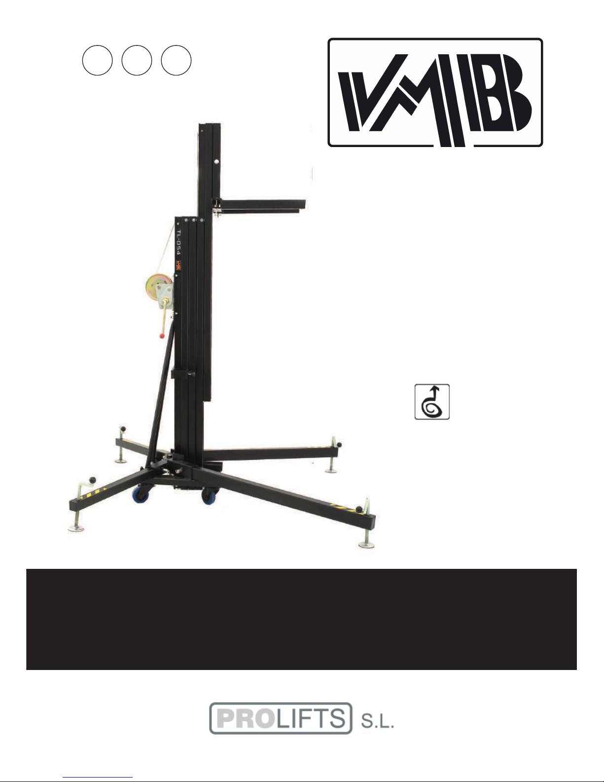
TOWERLIFT
TORRE ELEVADORA
TL-054 /
TL-056
GBE USA

LIFTING TOWER TL-054 / TL-056
TORRE ELEVADORA TL-054 / TL-056
PRO LIFTS S.L.
C/ Ciudad de Barcelona Nº19
Pol.Ind. Fuente del Jarro
46988 Paterna (Valencia)
Tlf Export: +34 96 171 81 86
Tlf Nacional: 96 171 81 83
Manufacturer - Fabricante
Este manual de usuario y catálogo anexo de piezas de repuesto es propiedad de PRO LIFTS S.L.
Queda prohibida su reproducción total o parcial por cualquier medio que la tecnología actual permita.
Deposito legal y copyright 2014. Todos los derechos reservados.
MADE IN SPAIN (EU)
BGV-C1
BGG-912
EC Conformity Declaration pursuant to the EC Machinery Directives 89/392/CE and
98/37/CE: Manual lifters
Find a copy of the certifications at the end of this booklet.
Puede ver una copia de las certificaciones al final del manual.
Features of the TL-054/56 towerlift / Características TL-054/56......3 - 4
English Quick operation guide....................................................................5 - 11
Manual de usuario Español.......................................................................... 12 - 18
Sketches / Planos piezas................................................................................ 19 - 26
Spare part list / Lista de repuestos..............................................................27 - 29
Certifications / Certificaciones......................................................................30 - 31
CONTENTS / ÍNDICE
Depósito legal y copyright 2014. Todos los derechos reservados. 3PRO LIFTS S.L.
T
V
V
S
T
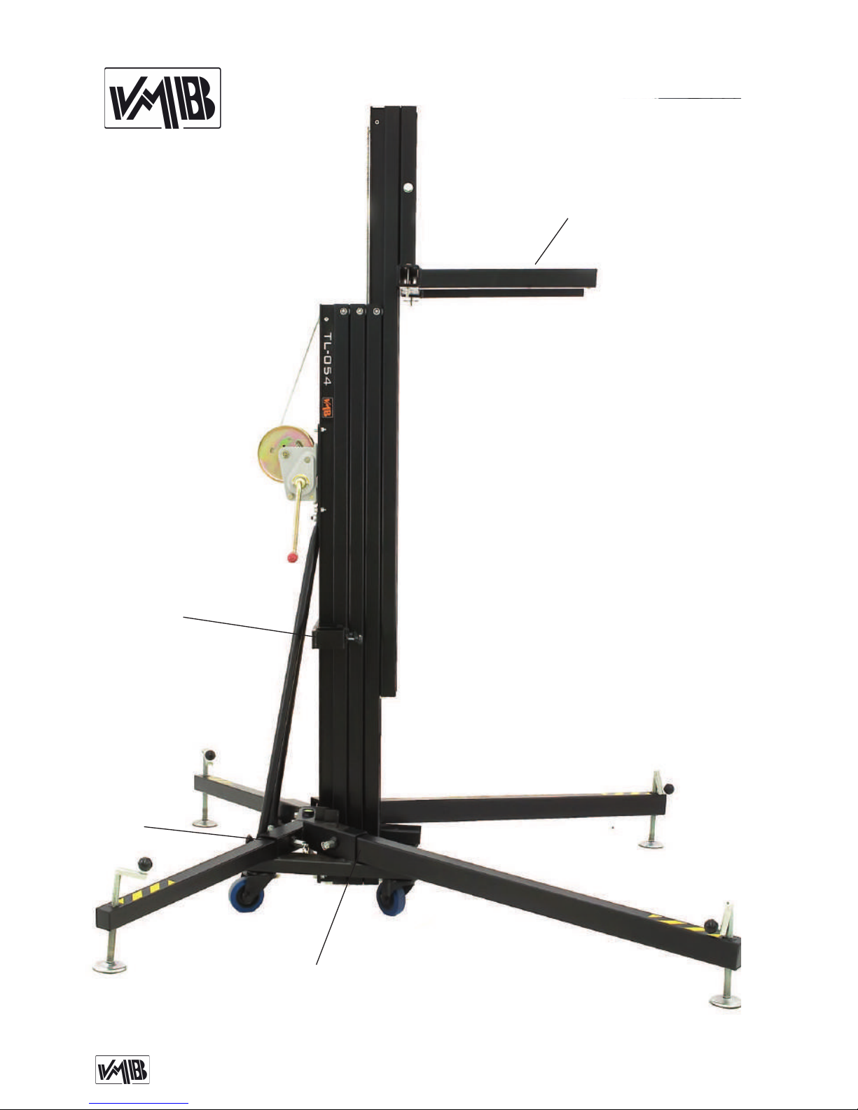
F: Forks / Brazos de carga
S: Transport compartment / Alojamiento de transporte
T: Transport wheels / Ruedas de transporte
V: Working compartment / Alojamiento de trabajo
F
TL-054 / TL-056
Depósito legal y copyright 2014. Todos los derechos reservados. 4PRO LIFTS S.L.
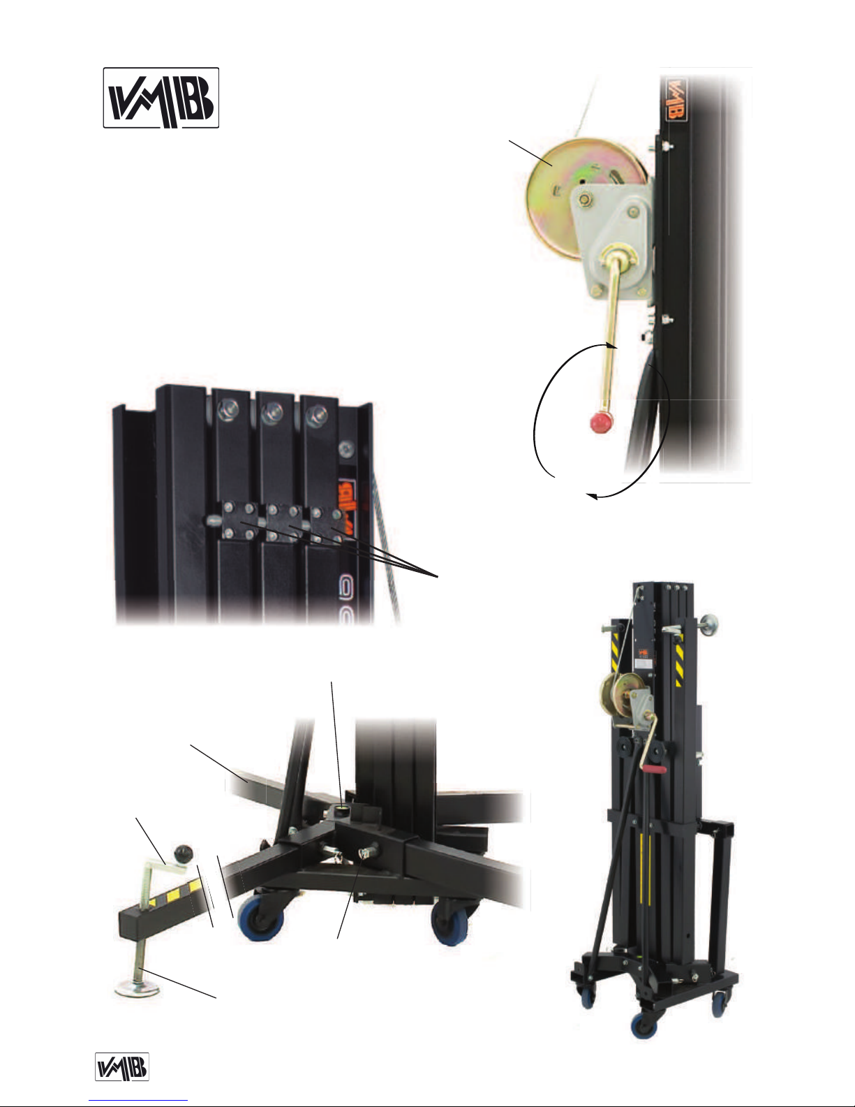
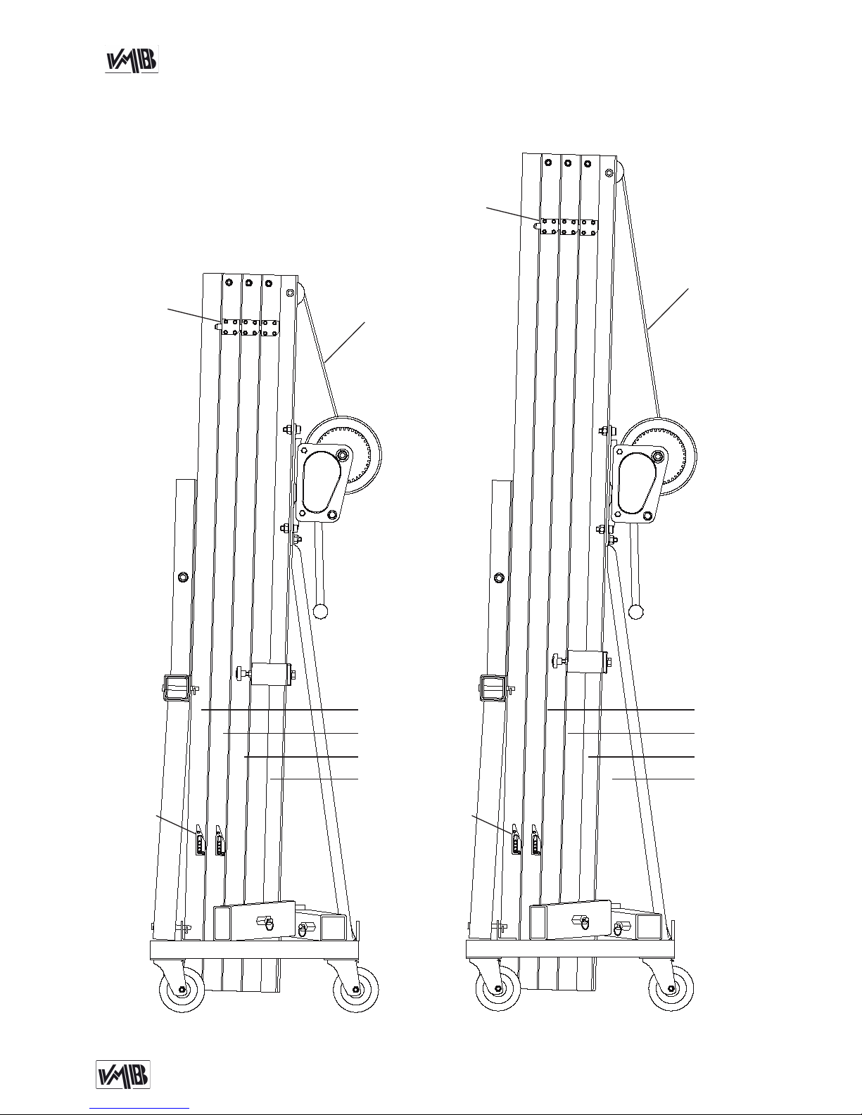
W
H: Handle / Manivela
L: Spirit level
N: Force on hand crank / Fuerza sobre manivela
P: Leg / Pata
Q: Stabilizer / Estabilizador
R: Catch pawl / Gatillo bloqueo patas
SRS: Sequence Retainer System
W: Winch / Cabrestante
N2
N1
R
P
H
Q
L
SRS
TL-054 /
TL-056

Depósito legal y copyright 2014. Todos los derechos reservados. 5PRO LIFTS S.L.
Quick operation guide ENGLISH
CONTENTS
1. Introduction.
2. Technical information.
3. Safety precautions.
4. Operation.
5. Maintenance.
6. Guarantee.
1. INTRODUCTION
Dear customer, in order to ensure a safe
and reliable operation of the TL-054 / TL-
056 towerlift please follow the instructions
in this booklet carefully. Before operating
the lift, read the instructions completely
and please note the technical information
contained within this manual.
All VMB products undergo very rigorous
testing, under strict conditions and they
are monitored continuously during the ma-
nufacturing process.
In order to guarantee the lifts function and
safety, only original parts from the manu-
facturer must be used. If any parts other
than those of the manufacturer are used,
or the product is modified in any way, the
user forfeits all warranty rights to claim.
VMB reserves the right to modify the pro-
duct specifications without prior notice.
The model type, production year and se-
rial number must be quoted in any queries
or orders for spare parts.
2. TECHNICAL INFORMATION
2.1 - TL-054 / TL-056 Towerlift.
2.2 - Designed to lift loads, such as trus-
sing and lighting systems, vertically, up to
different heights.
2.3 - Maximum load :
TL-054: 220 kg (485 lb).
TL-056: 200 kg (441 lb).
2.4 - Minimum load: 25 Kg (55 lb).
2.5 - Security : ILS (Inertial Lock Security).
2.6 - Maximum height :
TL-054: 5.45 m (17.8’).
TL-056: 6.5 m (21.3’).
2.7 - Folded height :
TL-054: 1.70 m (5.6’).
TL-056: 1.98 m (6.5’)
2.8 - Work surface :
2 x 2 m (6.6’ x 6.6’).
2.9 - Unit weight :
TL-054: 87 Kg (191 lb).
TL-056: 94.5 kg (208 lb).
2.10. - Load support:
Short forks (54.5 cm).
2.11 - Construction material : 6082-T6
alluminium for the main body, comprised
of 4 profiles and a lifting carriage. Base
and legs are made of steel profile accor-
ding to DIN 2394. Catches and pulleys of
ST-37 steel.
Depósito legal y copyright 2014. Todos los derechos reservados. 6PRO LIFTS S.L.
Quick operation guide ENGLISH
3. SAFETY PRECAUTIONS.
2.12 - Winch: 900 Kg Maximum load with
automatic brake.
Certification CE and GS TÜV.
2.13 - Cable : Steel DIN 3060. Quality 180
Kg/mm2twist resistant. Cable diameter: 5
mm
2.14 - Adjustable stabilizing feet with rub-
ber non-slip supports.
2.15 - Safety catches to anchor the legs.
2.16 - Antirust protection, primed paint
with cured polyester dust cover. The tower
can be supplied with natural aluminium
finish or black (version B).
2.17 - Spirit level to adjust the tower ver-
tically.
2.18 - Swivel wheels to transport the lift
when folded.
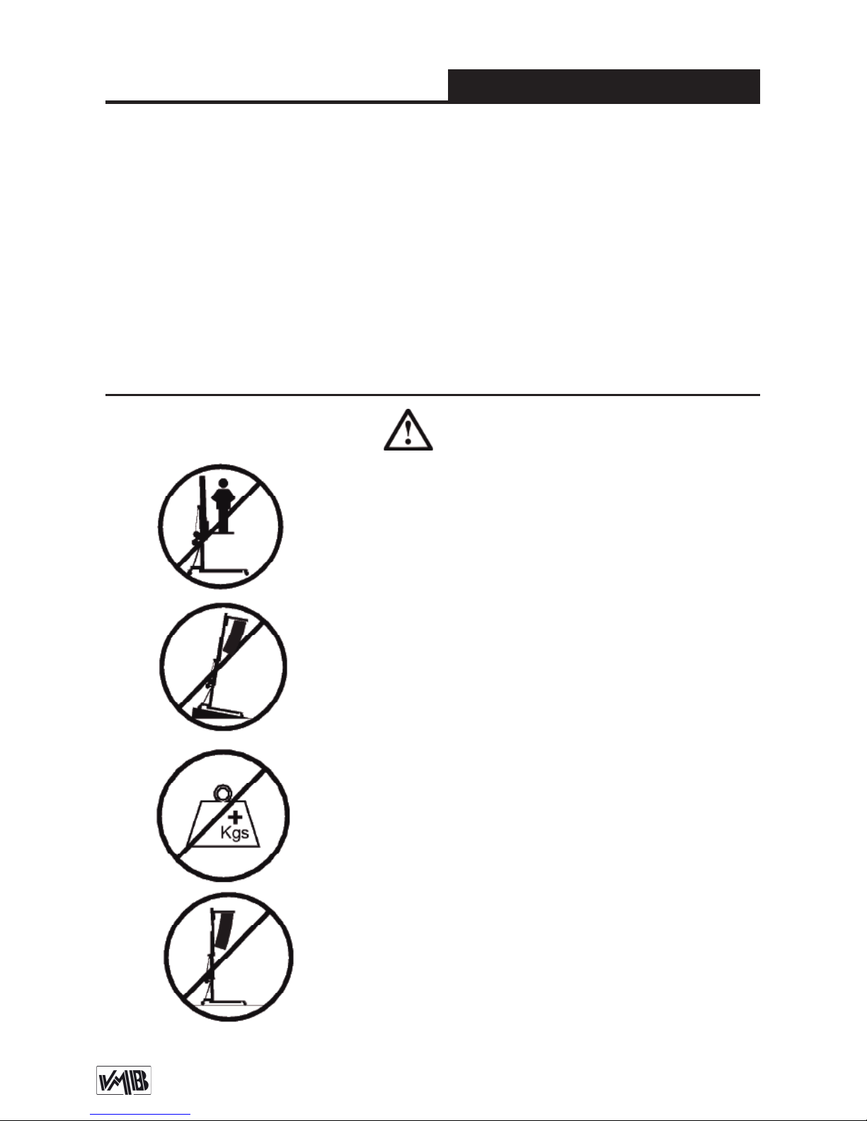
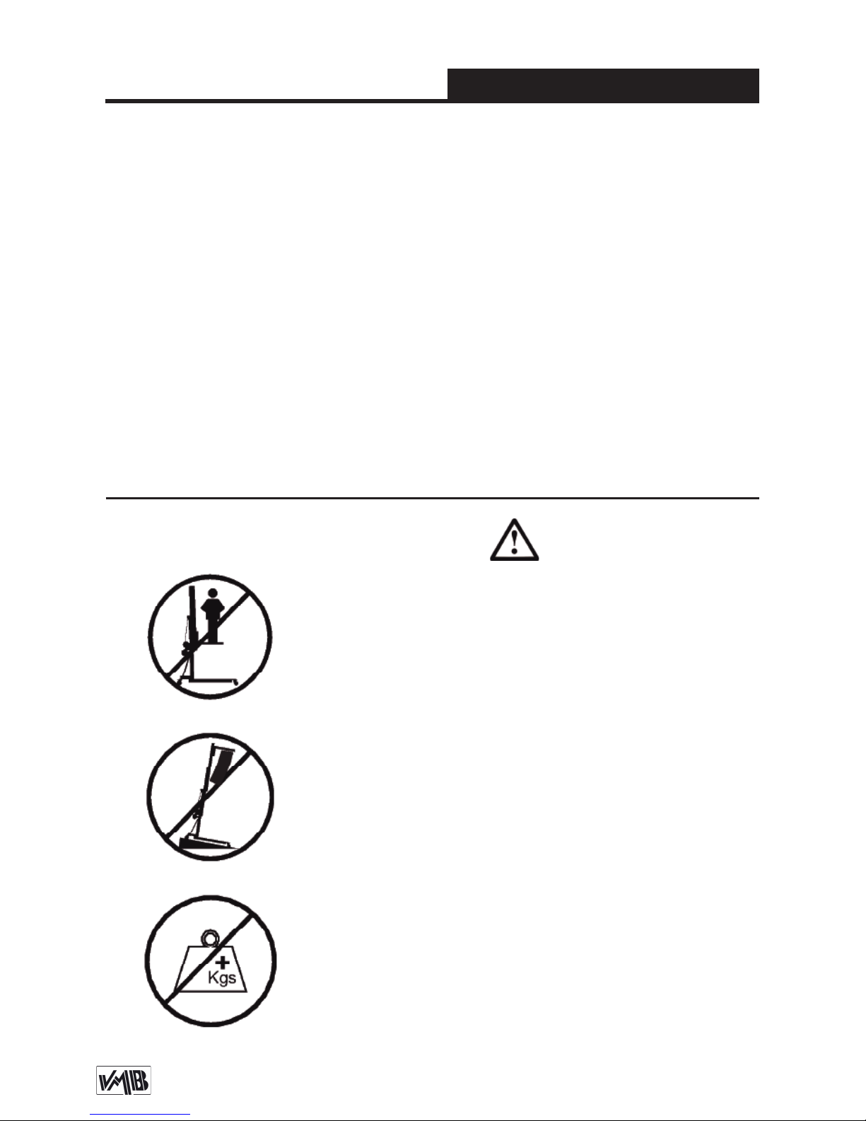
3.1 - The TL-054 / TL-056 is a machine designed to
elevate loads upwards in a vertical direction, It should
NEVER be used as a platform to elevate people.
3.3 - The maximum load indicated on the characteristics
label and the instructions manual should not be excee-
ded.
3.4 - This lift should NEVER be used to elevate a load
that has not been properly checked. It is necessary to
verify that the load is correctly supported and centred
on the appropriate lift support so that the weight of the
load will only elevate in a vertical direction.
3.2 - Only place the lift on hard, flat surfaces always
checking that it is in a vertical position by using the bub-
ble level indicator (L) found on the base. Adjust the leg
stabilizers (Q) by turning the handles (H) to level if ne-
cessary. NEVER use wedges or other foreign objects to
balance the lift.

Depósito legal y copyright 2014. Todos los derechos reservados. 7PRO LIFTS S.L.
Quick operation guide ENGLISH
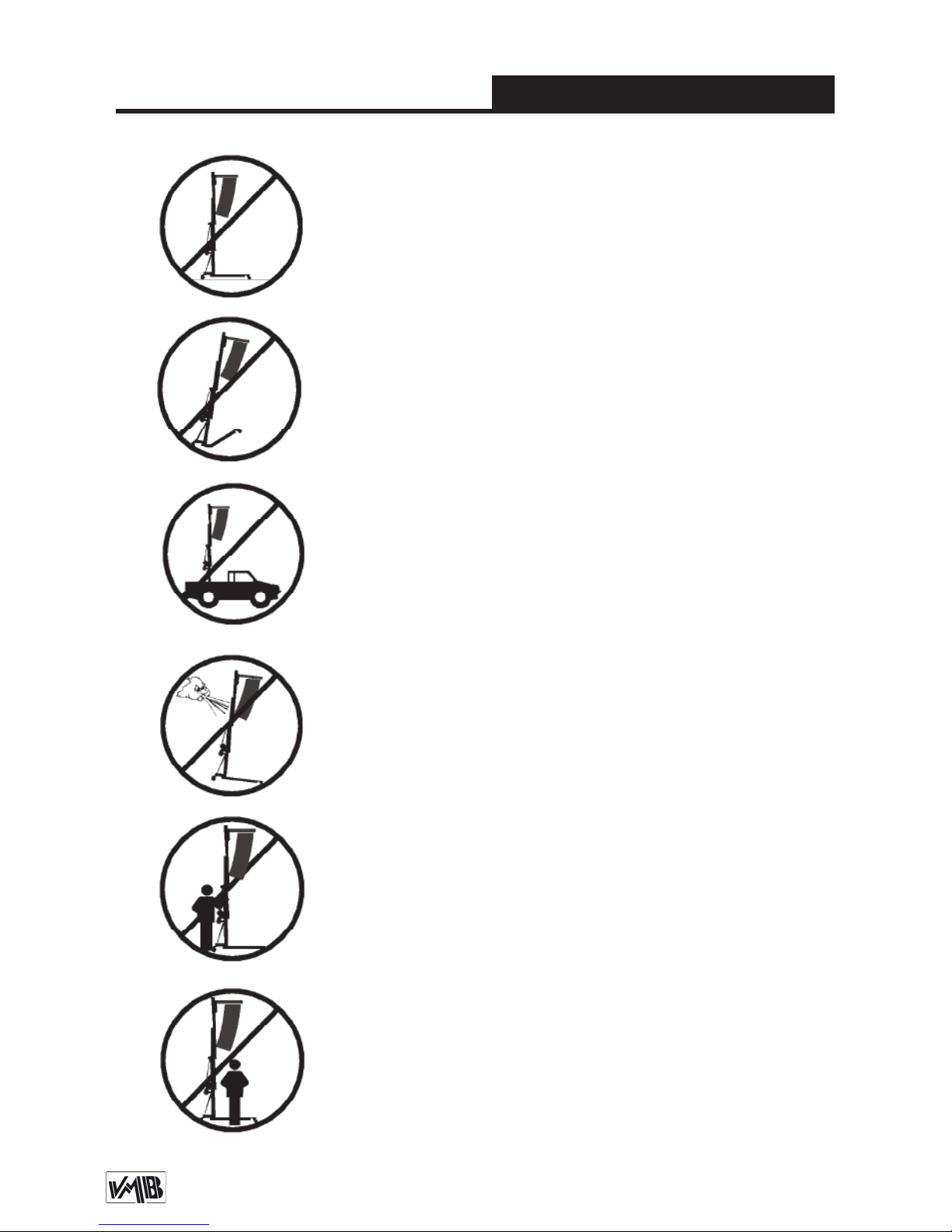
3.6 - NEVER use the lift on a vehicle or any other mobile
surface.
3.7 - If there is a possibility of strong winds or gusts,
place the lift on the ground firmly and secure it with the
use of straps. NEVER attach a strap to a vehicle or any
other object that can possibly be moved.
3.8 - NEVER move the lift whilst it is carrying a load. It
is not advisable to carry out any type of horizontal mo-
vement even small positional adjustments.
3.9 - NEVER allow any team member below the load or
anybody else in the lifts operating zone.
3.10 - Take care with all obstacles above the lift and
its extension zone such as cornices, balconies, and
luminous signboards. It is very important to avoid the
presence of all types of cables below the extended lift.
3.5 - Check that the legs (P) are placed and set-up co-
rrectly with their safety pins (R) inserted and locked.

Depósito legal y copyright 2014. Todos los derechos reservados. 8PRO LIFTS S.L.
Quick operation guide ENGLISH
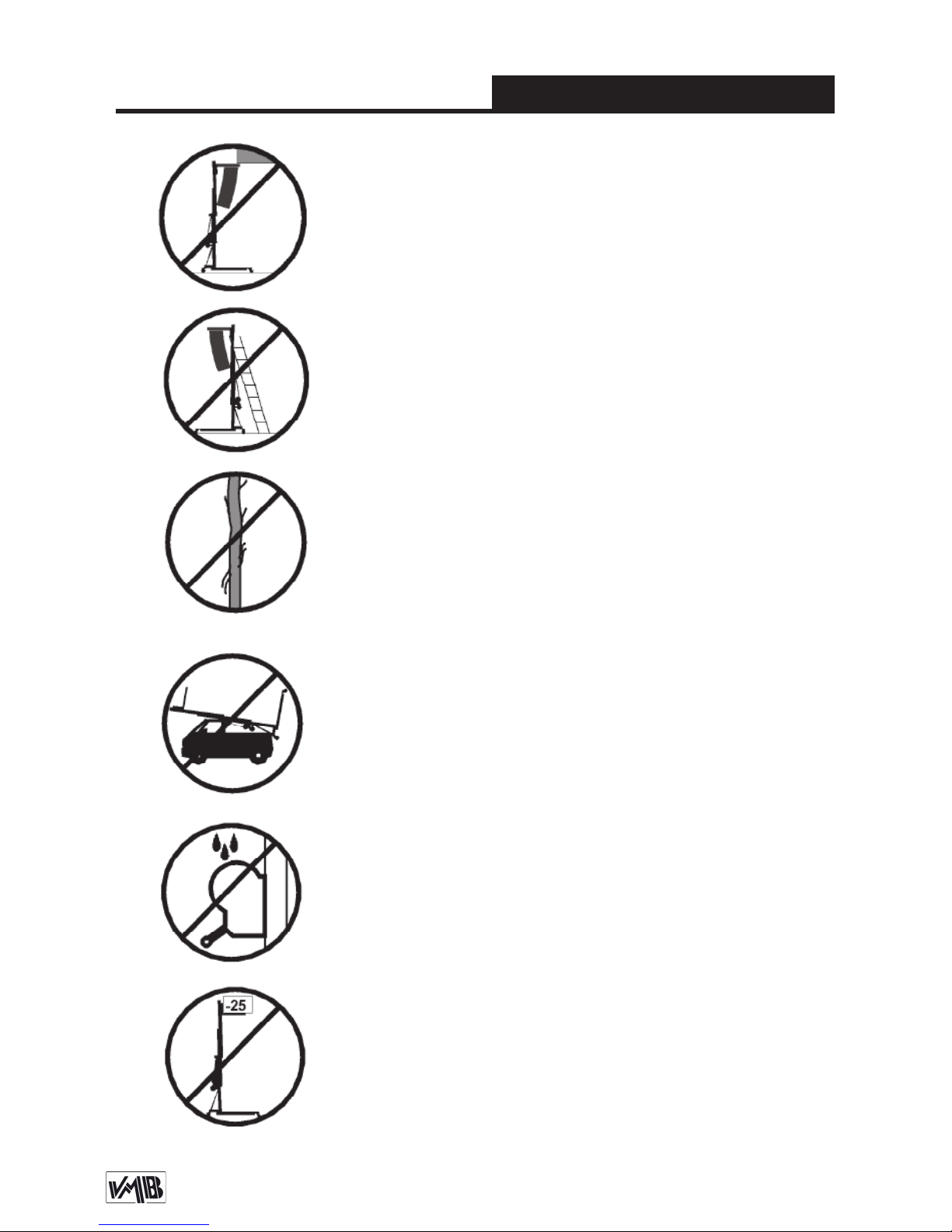
3.11 - Do not use stepladders on the lift or use it as a
support for them.
3.12 - Before using the lift, check the condition of the
cable. The cable should not have broken threads or
show any signs of crushed/flattened areas. NEVER use
faulty cables, always change them if there is any doubt.
Only use VMB steel cables; reference: DIN 3060.
Quality: 180KG/mm and torsion resistant.
3.14 - Do not grease or lubricate the winch’s braking
mechanism. The brake disks have been greased with
a special heat and pressure resistant solution. Other
products should not be used to avoid negative effects
regarding the braking mechanism.
3.15 - The minimum load to avoid problems regarding
the braking mechanism is 25Kg. Without this load the
brake will not work.
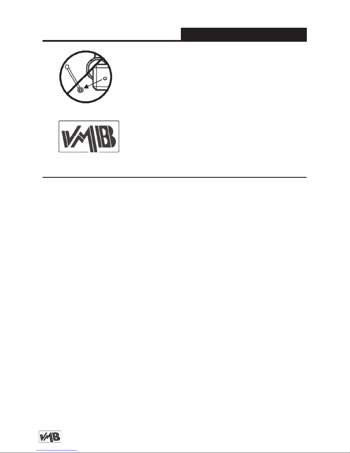
3.16 - NEVER take apart the crank of the winch when
the lift is carrying a load or extended.
3.13 - All sections must be lowered first, and the legs
placed in its transport position, before transportation.

Depósito legal y copyright 2014. Todos los derechos reservados. 9PRO LIFTS S.L.
Quick operation guide ENGLISH
3.17 - Only original replacement parts should be used.
ORIGINAL
4. USER INSTRUCTIONS.
4.1 - Place the lift on a firm, flat surface
in the area it is to be used with the help of
the transport wheels (T).
4.2 - Remove the legs (P) from their trans-
port compartment (S) and fully insert them
into their working positions (V) checking
that they are fixed by the pins (R).
4.3 - Check that the lift is in vertical posi-
tion using the spirit level (L) at the base of
the tower, adjust the stabilizer (Q), turning
the handle (H) if necesary.
4.4 - Release the forks (F) and place them
in its working position ready to take the
load on them. Insert the pins to block the
forks.
4.5 - DO NOT OVERLOAD THE LIFT.
TL-054 MAXIMUM LOAD IS 220 kg
TL-056 MAXIMUM LOAD IS 200 kg
The lift should NEVER be overloaded.
Safety at work is the most important is-
sue. Place the load onto the lift using an
adequate VMB support according to the
need, use so that the weight of the load
will only be elevated in a vertical direction.
The minimum load is 25 Kg.
4.6 - How to place the load: Always load
as close to the tower as possible.
The maximum load diminishes according
to the distance from the body of the tower
as illustrated in the diagram 4.6.1, which
shows the load on the gravity centre with
distances to the lifting carriage at a maxi-
mum lifting.
CAUTION
When two towers are used to elevate a
truss bridge, or many towers to elevate a
structure of any type, it is almost impos-
sible that two or more people co-ordinate
the winches elevating or lowering the
loads, at exactly the same pace. At a cer-
tain point each tower will be extended to
different height. For this reason it is ne-
cessary that the structure does not stretch
and allows for these differences.
With a rigid fixation and if the level diffe-
rence is significant, the force generated

Depósito legal y copyright 2014. Todos los derechos reservados. 10PRO LIFTS S.L.
Quick operation guide ENGLISH
This VMB system automatically blocks
each profile and the lifting carriage in the
unlikely event of cable breaking.
4.7 - Elevation:
Turn the winch crank clockwise (N1) to
lift the carriage. The unique SRS system
(Sequence Retainer System) will ensure
that the profiles rise in sequence, one af-
ter the other.
4.8 - Hold:
The tower can be left in any intermediate
position if it is necessary. Just stop turning
the handle of the winch and leave it. The
automatic brake of the winch will block it
and hold the load.
4.9 - Lowering:
To bring the lift down you need to first turn
the winch handle gently clockwise (N1) to
release the clutch of the winch. Then turn
the handle anti clockwise (N2) until all pro-
files have been completely lowered.
4.10 - Transport:
For the transport of the tower is necessary
to fold the machine lowering every profile
completely. Once the towerlift is comple-
tely folded, place the legs in their trans-
port compartment (S) and the lift will be
ready to be transported.
from the handle of the winch will deform
the structure and apply a lateral force to
the lifts causing them to break and block.
Security system ILS
The TL-054 / TL-056 incorporates the ILS
security system (Inertial Lock Security).
Diagram 4.6.1
B
C
D
E
A
Distance from the
load’s center to the
lifting carriage
Maximum load
TL-054 TL-056
A25 cm
(0.82’)
220 kg
(485 lb)
200 kg
(441 lb)
B30 cm
(0.98’)
198 kg
(437 lb)
180 kg
(397 lb)
C40 cm
(1.31’)
165 kg
(364 lb)
150
(331 lb)
D50 cm
(1.64’)
141 kg
(311 lb)
128
(282 lb)
For large forks:
E60 cm
(1.97’)
123 kg
(271 lb)
112 kg
(247 lb)

Depósito legal y copyright 2014. Todos los derechos reservados. 11PRO LIFTS S.L.
Quick operation guide ENGLISH
be found in this manual together with the
lift’s serial number and year of manufac-
ture.
6. GUARANTEE.
The warranty period for this lift is 2 years
from the date of purchase.
PRO LIFTS S.L. promises, that from the
date of purchase and during the warranty
period to resolve any faults that may oc-
cur, produced through defect material or
fabrication. Damage caused by improper
use, product modification, third party ma-
nipulation or accidental fire are not cove-
red by this warranty.
5. MAINTENANCE.
5.1 - Regularly check the state of the ca-
ble. If the cable has broken threads, or if
it shows any signs of crushed/flattened
areas, it should be changed and replaced
immediately with a new one. Do not use
the lift if the cables are in bad condition.
Only use VMB steel cables reference: DIN
3060 torsion resistant.
5.2 - The lift is supplied from the factory
completely greased. However, it is recom-
mended to periodically grease according
to use, the gearing, the axis bearings, the
spiral of the crank, and the sections.
5.3 - All lifts should undergo an annual
technical inspection carried out by an
authorized VMB dealer to check the cer-
tifications and general condition of all the
lift’s elements and security systems invol-
ved in the lift’s use.
5.4 - Only use original spare parts to gua-
rantee a continued security level. The
user loses all rights to warranty if any spa-
re parts other than originals are used or
carries out any modification or alteration
to the towerlift.
5.5 - To request a spare part please in-
dicate the corresponding code which can

Depósito legal y copyright 2014. Todos los derechos reservados. 12PRO LIFTS S.L.
Manual de usuario ESPAÑOL
CONTENIDO
1. Introducción.
2. Información técnica.
3. Precauciones de seguridad.
4. Instrucciones de uso.
5. Mantenimiento.
6. Garantía.
1. INTRODUCCIÓN
Estimado cliente: Con el fin de garantizar
un funcionamiento seguro y fiable de la
torre elevadora TL-054 / TL-056 por favor,
siga cuidadosamente las instrucciones de
este manual.
Antes de manipular la torre elevadora,
lea las instrucciones completas y tenga
en cuenta la información técnica conte-
nida en este manual. Todos los produc-
tos de VMB se someten a pruebas muy
rigurosas, en condiciones estrictas y son
monitorizados continuamente durante el
proceso de fabricación. Con el fin de ga-
rantizar el correcto funcionamiento y se-
guridad de los elevadores, sólo deben ser
utilizadas piezas originales del fabricante.
Si se utilizan piezas que no sean las origi-
nales del fabricante, o el producto se mo-
difica de alguna manera, el usuario pierde
todos los derechos de garantía.
VMB se reserva el derecho de modificar
las especificaciones y las piezas del pro-
ducto sin previo aviso. El tipo de modelo,
año de producción y el número de serie
deben ser citadas en cualquier consulta o
pedido de piezas de recambio.
2. INFORMACIÓN TÉCNICA
2.1 - Torre elevadora TL-054 / TL-056.
2.2 - Diseñada para levantar estructuras,
trusses e iluminación en sentido vertical a
diferentes alturas.
2.3 - Carga máxima:
TL-054: 220 kg (485 lb).
TL-056: 200 kg (441 lb).
2.4 - Carga mínima: 25 Kg (55 lb).
2.5 - Seguridad: ILS (Bloqueo de inercia).
2.6 - Altura máxima:
TL-054: 5.45 m (17.8’).
TL-056: 6.5 m (21.3’).
2.7 - Altura plegada:
TL-054: 1,70 m (5.6’).
TL-056: 1.98 m (6.5’).
2.8 - Área de la base:
2 x 2 m (6.6’ x 6.6’).
2.9 - Peso de la torre:
TL-054: 87 kg (191 lb).
TL-056: 94.5 kg (208 lb).
2.10 - Soporte de carga:
Brazos de carga cortos de 54.5 cm.
2.11 - Material de construcción: Cuerpo
principal de cuatro tramos más carro ele-
vador en perfil de aluminio extrusionado
Depósito legal y copyright 2014. Todos los derechos reservados. 13PRO LIFTS S.L.
Manual de usuario ESPAÑOL
3. PRECAUCIONES DE SEGURIDAD
6082-T6. Base, patas y soportes varios,
en perfileria de acero según DIN 2394.
Gatillos de seguridad y poleas acanala-
das en acero ST-37.
2.12 - Cabestrante: 900 kg de carga máxi-
ma con freno automático de retención de
la carga. Certificación CE y GS TÜV.
2.13 - Cable: Acero DIN 3060. Calidad de
resistencia a la torsión 180 kg/mm2.
Diámetro del cable: 5 mm.
2.14 - Patas estabilizadoras ajustables
con soportes de goma antideslizante.
2.15 - Gatillos de seguirdad para anclar
las patas.
2.16 - Protección anti-óxido, imprimación
con pintura de polvo poliester al horno. La
torre puede ser suministrada con acaba-
do natural de aluminio o negro (versión
B).
2.17 - Nivel de burbuja para ajustar la ver-
ticalidad de la torre.
2.18 - Ruedas direccionales para el trans-
porte de la torre cuando este plegada.
3.1 - La torre elevadora TL-054 / TL-056 es una máqu-
na diseñada para la elevación de cargas en dirección
vertical. NUNCA se debe utilizar como plataforma elea-
vadora de personas.
3.3 - La carga máxima indicada en las características
técnicas mostradas en la etiqueta de la torre o en este
manual NO deben ser excedidas.
3.2 - Colocar el elevador sólo en superficies firmes y
planas, verificando que está en posición vertical, utili-
zando el indicador de nivel de burbuja (L) que se en-
cuentra en la base. Ajuste los estabilizadores (Q) gi-
rando las manivelas (H) hasta nivelar, si es necesario.
Nunca utilice cuñas u otros objetos extraños para equi-
librar el elevador.
Depósito legal y copyright 2014. Todos los derechos reservados. 14PRO LIFTS S.L.
Manual de usuario ESPAÑOL
3.6 - NUNCA use el elevador sobre un vehículo o cualquier
superficie móvil.
3.7 - Si existe la posibilidad de vientos fuertes o ráfagas,
coloque el elevador en el suelo con firmeza y fijelo mediante
tirantes tensores. Nunca fije un tirante a un vehículo o cual-
quier otro objeto que se pueda mover.
3.8 - NUNCA mueva el elevador mientras esté cargado. No
es aconsejable llevar a cabo cualquier tipo de movimiento
horizontal, ni tan sólo pequeños ajustes de posición.
3.9 - NUNCA permita que ningún miembro del equipo o
cualquier otra persona se sitúe debajo de la carga en la
zona de operación de las torres elevadoras.
3.5 - Comprobar que las patas (P) estén situadas correcta-
mente, y fijadas con los gatillos de seguridad (R) los cuales
deben estar introducidos y bloqueados.
3.4 - Este elevador NUNCA debe utilizarse para elevar una
carga que no ha sido correctamente revisada. Es necesario
verificar que la carga está correctamente apoyada y centra-
da en el soporte de elevación apropiado para que el peso de
la carga sólo actúe en una dirección vertical.
Depósito legal y copyright 2014. Todos los derechos reservados. 15PRO LIFTS S.L.
Manual de usuario ESPAÑOL
3.12 - Antes de utilizar el elevador, compruebe el estado
del cable. El cable no debe contener hilos rotos o mostrar
signos de áreas aplastadas/aplanadas.
NUNCA use cables defectuosos, siempre debe cambiarlos
si hay alguna duda. Utilice solamente cable de acero VMB
referencia: DIN 3060. Calidad: 180kg/mm y resistente a la
torsión.
3.13 - Antes de transportar la torre, todos los tramos deben
ser bajados, y las patas deben extraerse y colocarse en su
posición de transporte.
3.14 - No engrasar ni lubricar el mecanismo de freno del
cabestrante. Los discos de freno vienen engrasados con
una solución especial resistente a la presión y al calor. No
deben utilizarse otros productos, para evitar los efectos
negativos sobre el mecanismo de frenado.
3.15 - La carga mínima para evitar problemas relaciona-
dos con el mecanismo de rotura es 25 kg. Sin esta carga
mínima el freno no funcionará.
3.11 - No usar escaleras encima del elevador ni utilizarlo
como un apoyo para éstas.
3.10 - Tenga cuidado con todos los obstáculos por encima
de la elevación y su zona de extensión, como cornisas,
balcones, letreros luminosos, etc. Es muy importante evi-
tar la presencia de todo tipo de cables por debajo de la
torre extendida.
Depósito legal y copyright 2014. Todos los derechos reservados. 16PRO LIFTS S.L.
Manual de usuario ESPAÑOL
4. INSTRUCCIONES DE USO.
4.1 - Coloque el elevador sobre una su-
perficie firme y plana de la zona de traba-
jo sirviendose de las ruedas direccionales
de transporte (T).
4.2 - Extraiga las patas (P) de su aloja-
miento para transporte (S) e insertelas
totalmente en su posición de trabajo (V),
comprobando que los gatillos de seguri-
dad (R) se insertan y fijan la pata.
4.3 - Compruebe que la torre esta en
posición vertical sirviendose del nivel de
burbuja (L) situado en el perfil base, si es
necesario ajuste la vertical de la torre con
los estabilizadores (Q) de las patas, giran-
do las manivelas (H).
4.4 - Libere los brazos de carga (F) y colo-
quelos en posición horizontal e inserte los
pasadores de seguridad.
4.5 - LA CARGA MÁXIMA PARA TL-054
ES 220 kg (485 lb) (200kg para TL-056).
El elevador NUNCA debe ser sobrecarga-
do. La Seguridad en el Trabajo es el ele-
mento más importante. Coloque la carga
en el elevador mediante un soporte ade-
cuado según la necesidad de modo que
el peso de la carga sólo actúe en direc-
ción vertical. La carga mínima son 25 kg.
4.6 - Como colocar la carga:
Cargue siempre tan cerca de la torre
como pueda. La capacidad de carga de
la torre decrece cuanto más lejos este la
carga separada de la torre, como se ilus-
tra en el esquema (4.6.1) de la siguiente
página. El cual muestra la carga en su
centro de gravedad con distancias al ca-
rro elevador que sostiene los brazos y a
máxima altura.
3.17 - Sólo deben ser utilizadas piezas de repuesto
originales de VMB PRO LIFTS S.L.
ORIGINAL
3.16 - NUNCA desmontar la manivela del cabrestante
cuando el elevador está soportando una carga o exten-
dido.

Depósito legal y copyright 2014. Todos los derechos reservados. 17PRO LIFTS S.L.
Manual de usuario ESPAÑOL
B
C
D
E
A
re y permita estas diferencias. Con una
fijación rígida y si la diferencia de nivel es
importante, la fuerza generada a partir de
la manivela del cabrestante deformará la
estructura y aplicará una fuerza lateral a
los elevadores provocando su bloqueo y
ruptura.
Sistema de seguridad ILS
La torre elevadora TL-054 / TL-056 incor-
pora el sistema de seguridad ILS (Blo-
queo de inercia). Este sistema de VMB
bloquea automáticamente la torre en el
caso inprobable de rotura del cable de
acero.
4.7 - Elevación:
Gire la manivela del cabestrante en sen-
tido horario (N1) para elevar el carro. El
sistema retentor SRS asegurará que los
perfiles se elevan de forma secuencial,
uno detrás de otro.
4.8 - Bloqueo:
La torre puede dejarse en cualquier posi-
ción intermedia si se requiere. Una vez el
sistema esta elevado hasta la altura de-
seada tan solo deje de girar la manivela
y el freno automático del cabrestante blo-
queará y sujetará la carga.
4.9 - Descenso:
Para descender la torre es necesario,
primero girar la manivela del cabrestante
ligeramente en sentido horario (N1) para
liberar el embrague del cabrestante y a
continuación, girar la manivela en sentido
anti-horario (N2) hasta que todos los perfi-
les estén completamente bajados.
PRECAUCIÓN
Cuando se utilizan dos torres para elevar
un puente, descender truss o varias torres
para elevar una estructura de cualquier
tipo, es casi imposible que dos o más per-
sonas coordinen los cabrestantes exacta-
mente a la misma velocidad al elevar o
bajar las cargas. En un momento deter-
minado cada torre se elevará a una altura
diferente a la de las demás. Por ello, es
necesario que la estructura no se esti-
Esquema 4.6.1
Distancia del
centro de la carga
al carro elevador
Carga máxima
TL-054 TL-056
A25 cm
(0.82’)
220 kg
(485 lb)
200 kg
(441 lb)
B30 cm
(0.98’)
198 kg
(437 lb)
180 kg
(397 lb)
C40 cm
(1.31’)
165 kg
(364 lb)
150
(331 lb)
D50 cm
(1.64’)
141 kg
(311 lb)
128
(282 lb)
Para brazos de carga largos:
E60 cm
(1.97’)
123 kg
(271 lb)
112 kg
(247 lb)

Depósito legal y copyright 2014. Todos los derechos reservados. 18PRO LIFTS S.L.
Manual de usuario ESPAÑOL
a una inspección técnica anual llevada a
cabo por un distribuidor autorizado VMB
para comprobar las certificaciones y el
estado general de todos los elementos de
elevación y sistemas de seguridad que in-
tervienen en el uso del elevador.
5.4 - Utilice únicamente piezas de repues-
to originales para garantizar el nivel de
seguridad de forma continuada. El usua-
rio pierde todos los derechos de garantía
si las piezas de repuesto utilizadas no son
originales o se utilizan o se lleva a cabo
cualquier modificación o alteración de la
torre elevadora.
5.5 - Para solicitar una pieza de recam-
bio indique el código correspondiente que
se encuentra en este manual junto con el
número de serie de la torre y el año de
fabricación.
6. GARANTÍA
El período de garantía para este elevador
es de 2 años a partir de la fecha de com-
pra.
PRO LIFTS S.L. se compromete, que a
partir de la fecha de compra y durante el
período de garantía, a resolver los fallos
que puedan producirse, debidos a mate-
rial defectuoso o fabricación. Los daños
causados por un uso inadecuado, modi-
ficación del producto, la manipulación de
terceros o incendio accidental no están
cubiertos por esta garantía.
4.7 - Transporte:
Para el transporte de la torre es necesa-
rio bajar completamente todos los tramos.
Una vez la torre haya sido plegada, co-
loque las patas en su alojamiento para
transporte (S) y la torre ya estará lista
para su transporte.
5. MANTENIMIENTO
5.1 - Comprobar periódicamente el esta-
do del cable. Si en el cable existen hilos
rotos, o si muestra signos de zonas aplas-
tadas/aplanadas, debe ser sustituido in-
mediatamente por uno nuevo. No use el
elevador si los cables están en mal esta-
do. Utilice solamente cable de acero DIN
3060 resistente a la torsión.
5.2 - La torre elevadora es suministrada
de fábrica completamente engrasada.
Sin embargo, se recomienda un engrase
periódico, según el uso, de las ruedas de
fricción, los cojinetes de eje, la espiral de
la manivela, y los tramos.
RECUERDE: NUNCA engrasar ni lubricar
el mecanismo de freno. No es necesario
engrasar los discos de freno. Los discos
de freno vienen engrasados con una so-
lución especial resistente a la presión y
al calor. No deben utilizarse otros produc-
tos, para evitar los efectos negativos so-
bre el mecanismo de frenado.
5.3 - Todos los elevadores se someten

Depósito legal y copyright 2014. Todos los derechos reservados. 19PRO LIFTS S.L.
TL-054 & TL-056 SPARE PARTS SKETCHES /
CROQUIS DE LAS PIEZAS DE REPUESTO DE TL-054 y TL-056
Profiles / Barras.............................................................................................21
TL-054 Profiles / Barras TL-054
TL-056 Profiles / Barras TL-056
A.1 SRS System / Sistema retentor SRS
A.2 Cable fixation / Prisionero cable
A.3 Base profile lower area / Zona inferior perfil Base
A.4 Profile upper area / Zona superior barras
A.5 Alluminium stop piece / Pieza de aluminio tope barras
Base / Base....................................................................................................23
B.1 Wheels / ruedas
B.2 Screws for the base / Tornillería de la Base
B.3 Reinforcing struts / Tirantes de refuerzo
B.4 Leg locks / Gatillos patas
B.5 Pin and “R” clip / Pasadores y clips “R”
Winch / Cabrestante......................................................................................24
Forks / Brazos de carga
Fork support / Soporte brazos de carga
Lifting carriage / Carro elevador..................................................................25
D.1 Fixation screw for fork support /
Tornillo fijador soporte brazos de carga
D.2 Nylon roller / Rodillos
D.3 Inertial break / Freno de inercia
D.4 Profile stop piece / Taco tope barra
D.5 Pulley system of the carriage lower area /
Sistema de rodillos y poleas inferior carro
Legs / Patas....................................................................................................26
E.1 Leg transport support / Porta-patas para transporte
E.2 Complete legs and legs profile / Patas completas, y perfiles patas
E.3 Complete stabilizer kit and stabilizer exploded /
Estabilizador completo y despiece estabilizador
A
B
C
D
E
Depósito legal y copyright 2014. Todos los derechos reservados. 20PRO LIFTS S.L.
TL-054 / TL-056
5437
5473
5472
5471
5470
5425
5477
5476
5475
5474
A.1
A.1
A.1
A.1
TL-056
TL-054
Other manuals for TL-054
1
This manual suits for next models
1
Table of contents
Languages:
Other VMB Lifting System manuals


Popular Lifting System manuals by other brands


ABS
ABS Sanimat 1501S Installation and operating instructions

Altair
Altair 55030 user manual

tirak
tirak XA 300 Series instruction manual

Pacific Hoists
Pacific Hoists My-T-Lift manual

LGMG
LGMG SS1230E Operation and safety manual

Joerns Healthcare
Joerns Healthcare Hoyer HPL402 User instruction manual & warranty


