VMB TL-A300 User manual

v12.03 - Depósito legal y Copyright 2012. Todos los derechos reservados.
PRO L IFTS S.L.
TL - A300
EELEVADOR LINE ARRAY
MANUAL DE INSTRUCCIONES
LINE ARRAY LIFT
INSTRUCTION MANUAL
Quick Operation Guide
GB
DTRAVERSENLIFT
BEDIENUNGSANLEITUNG
Fabricante - Manufacturer - Hersteller - Fabricant
TORRE ELEVADORA
TOWERLIFT
TRAVERSENLIFT
PIED ÉLÉVATEUR
TL-A300
Este manual de usuario y catálogo anexo de piezas de repuesto es propiedad de PRO LIFTS S.L.
Queda prohibida su reproduccion total o parcial por cualquier medio que la tecnología actual permita.
Depósito legal y Copyright 2012. Todos los derechos reservados.
PRO LIFTS S.L.
Calle 7 final - Pol. Ind. Picassent
E-46220 Picassent (VALENCIA) SPAIN
www.prolifts.es - info@prolifts.es
v12.03 - Depósito legal y Copyright 2012. Todos los derechos reservados.
PRO L IFTS S.L.
TL-A300
RTS
ALS
V
P
Q
H
T
R
C
B
FILS
BA
E
D
P1
BU
W
N1
N2
P1
BU

v12.03 - Depósito legal y Copyright 2012. Todos los derechos reservados.
PRO L IFTS S.L.
CONTENTS
1. Introduction.
2. Technical Data.
3. Security.
4. Instructions.
5. Maintenance.
6. Warranty.
7. Certifications.
1. INTRODUCTION
Thank you for choosing VMB Towerlifts.
You have acquired a first class, quality product
used by professionals around the world.
To be able to work with this tower, lifting and
flying PA and Line Array, please pay special
attention to this manual. Please observe the
technical data and follow all instructions fully
for a correct and safe use.The manual should
also be made available and remain with the
towerlift.
All VMB towerlifts undergo a strict quality
control to guarantee maximum safety and
durability.
The TL-A300, has been especially designed
and engineered to hang Line Array to a
maximum height of 5.8m and a load of 300kg.
This lift is capable of situating the PA 50cm
from the body of the lift.
The benefit of placing the load at a distance
enables the user to achieve the perfect curve
and coverage for the Line array flown.
The TL-A300, incorporates the ALS system
(Auto-Lock-Security), ILS system (Inertia-
Lock-Security) all exclusive to VMB and which
provide complete safety & guarantee the load
will not fall. It also includes the SRS system
(Sequence-Retainer-System) which enables
the profiles to rise in sequence, one after the
other.
2. TECHNICAL IINFORMATION
2.1 – Towerlift mod. TL-A300
2.2 – Especially designed for lifting and flying
Line array directly from the floor to a height of
5.8m (19’). Able to hang at 50cm (1.6’) from
the main body of the lift.
2.3 – Maximum load : 300Kg (662lb) . at 50cm
(1.6’) from lift body..
2.4 – Minimum Load : Can lift or lower without
load.
2.5 – Maximum Height : 5.8m (19’).
2.6 – Folded Height : 1.58m (5.2’).
2.7 – Base Surface : 1.9 x 2.1m (6.2’ x 6.9’).
2.8 – Transport Weight : 165Kg (364lb).
2.9 – Construction Material : 6082-T6
aluminium for the main body comprised of 4
profiles and lifting carriage. DIN 2394 steel for
the base and outriggers. ST-37 steel for the
ALS security system and pulleys.
2.10 – Security Systems: ALS (Auto-Lock-
Security), ILS (Inertia-Lock-Security) which
guarantee complete security at all times.
During the life of this towerlift, it may need
spare parts for maintenance. In this case
please contact your distributor.
Only original spare parts must be used. The
user loses all rights to warranty if any spare
parts other than originals are used or carries
out any modification or alteration to the
towerlift.
For any questions relating to this towerlift
please indicate serial number and year of
production.
Quick Operation Guide ENGLISH

v12.03 - Depósito legal y Copyright 2012. Todos los derechos reservados.
PRO L IFTS S.L.
Quick Operation Guide ENGLISH
2.11 – 900kg Manual winch with automatic
disc brake.
2.12 – Cable : DIN 3060 steel. 180 Kg/mm2
quality antitorsion. 6 mm diametre.
2.13 – Adjustable stabilisers on the
outriggers with anti-slip injected rubber base.
2.14 – Outriggers fixed with security locks.
2.15 – Spirit level to adjust vertical positioning.
2.16 – All lift elements are finished in polyester
satin black.
2.17 – 360º Wheels for ease of transport to
work place.
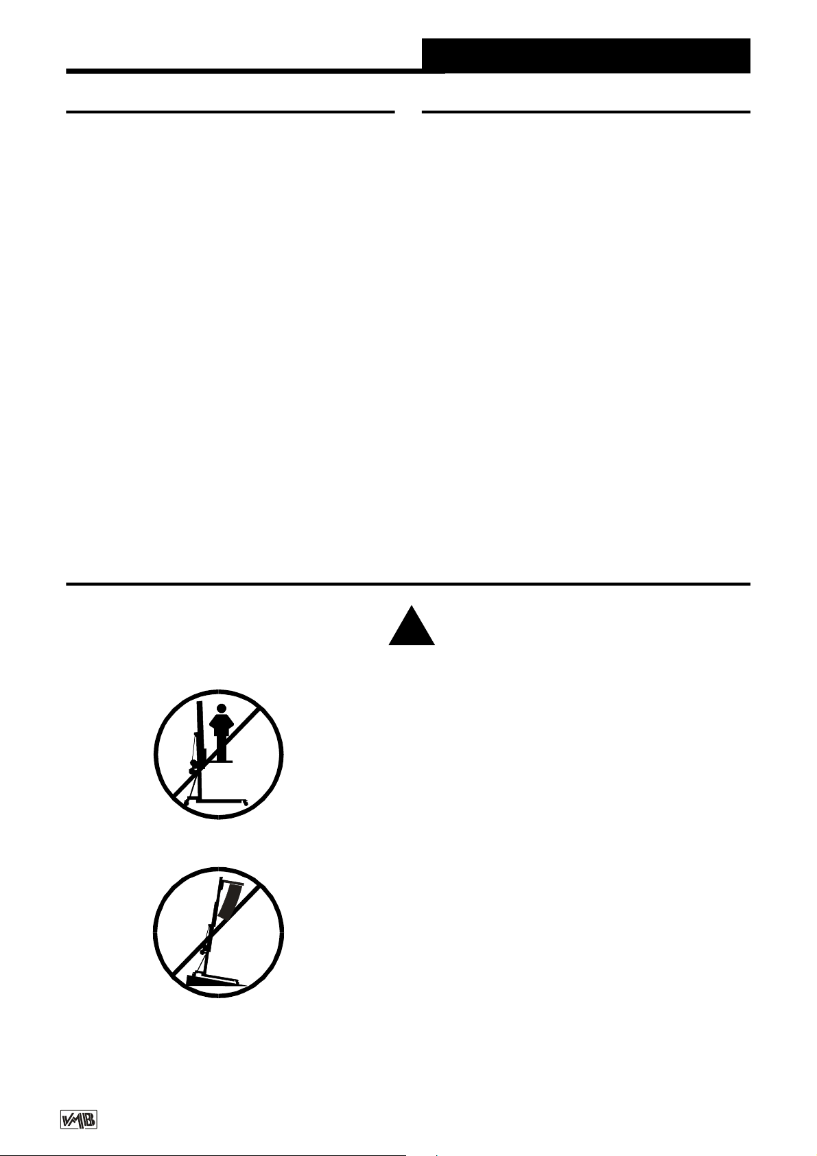
3. SAFETY PRECAUTIONS.
3.1 – The TL-A300 is designed for lifing
Line Array and should never be used for
elevating persons.
3.2 – Only situate the lift on hard, flat
surfaces checking that it is in a vertical
position with the spirit level (F) included. If
necessary, adjust with support stabilisers
(Q) by turning the handle (H). Do not use
any other materials to balance the lift.
3.3 – Check all outriggers are inserted
correctly and locked with security locks.
!

v12.03 - Depósito legal y Copyright 2012. Todos los derechos reservados.
PRO L IFTS S.L.
Quick Operation Guide ENGLISH
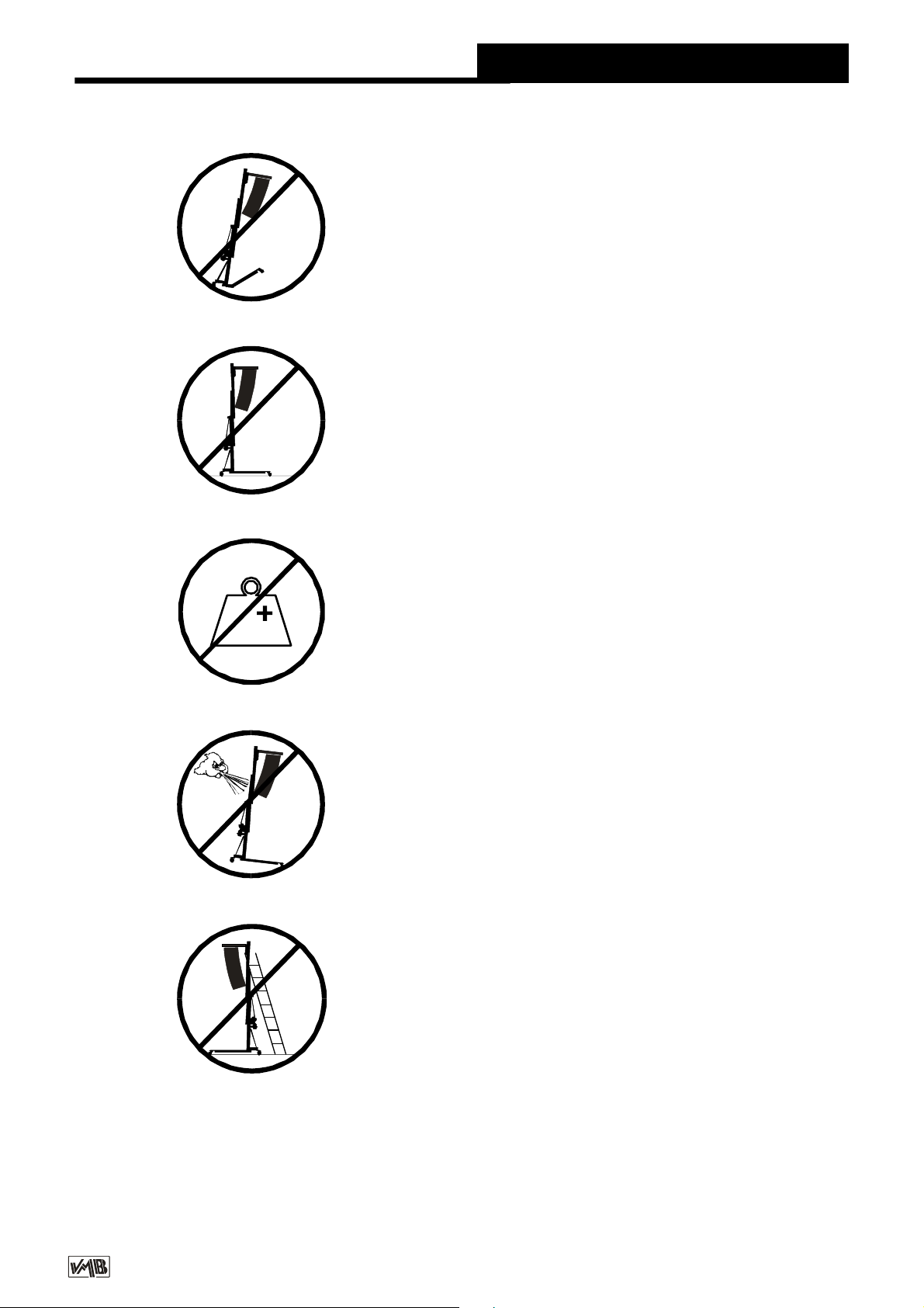
3.5 – Never exceed the maximum weight
indicated on the towerlift and in this ma-
nual.
3.4 – Never elevate the Line Array before
checking it is correctly attached to the lift.
Kgs
3.6 – If there is excessive wind, place the
lift on firm ground and attach slings to add
stability. Never attach a sling to a vehicle
or any other element than can move.
3.8 – Be carfeful of any high, obstructions
such as balconies, signs etc. It is important
to avoid the presence of cables beneath
the working position of the lift.
3.7 – Do not use a ladder on the lift.

v12.03 - Depósito legal y Copyright 2012. Todos los derechos reservados.
PRO L IFTS S.L.
Quick Operation Guide ENGLISH
3.11 – Never use the lift on a mobile surface
or on any vehicle.
3.10 – Never try to move the lift once the
load is raised.
3.9 – Never stand below the raised mate-
rial and do not allow others to stand
beneath or around the working area of the
lift.
3.12 – Before using the lift check the
condition of the cable. The cable should
not be broken or torn. NEVER use defect
cables and if in doubt change the cable.
Only use DIN 3060 steel cable 180 Kg/
mm2quality torsion resistant cable.
3.13 – Never remove the handle from the
winch if the lift is elevated with load.

v12.03 - Depósito legal y Copyright 2012. Todos los derechos reservados.
PRO L IFTS S.L.
3.16 – All profiles must be lowered before
the lift is transported.
3.15 – Do not grease or lubricate the break
mechanism in the winch. The break discs
have been especially greased with a
special anti heat, pressure material.
Other products must not be used so as to
avoid the break not working effectively.
3.14 – The minimum load for the brake
functioning in the winch is 25kg. Without
this weight the brake will not function.
3.17 – Only original spares must be used.
OR IGINAL
-25
Quick Operation Guide ENGLISH

v12.03 - Depósito legal y Copyright 2012. Todos los derechos reservados.
PRO L IFTS S.L.
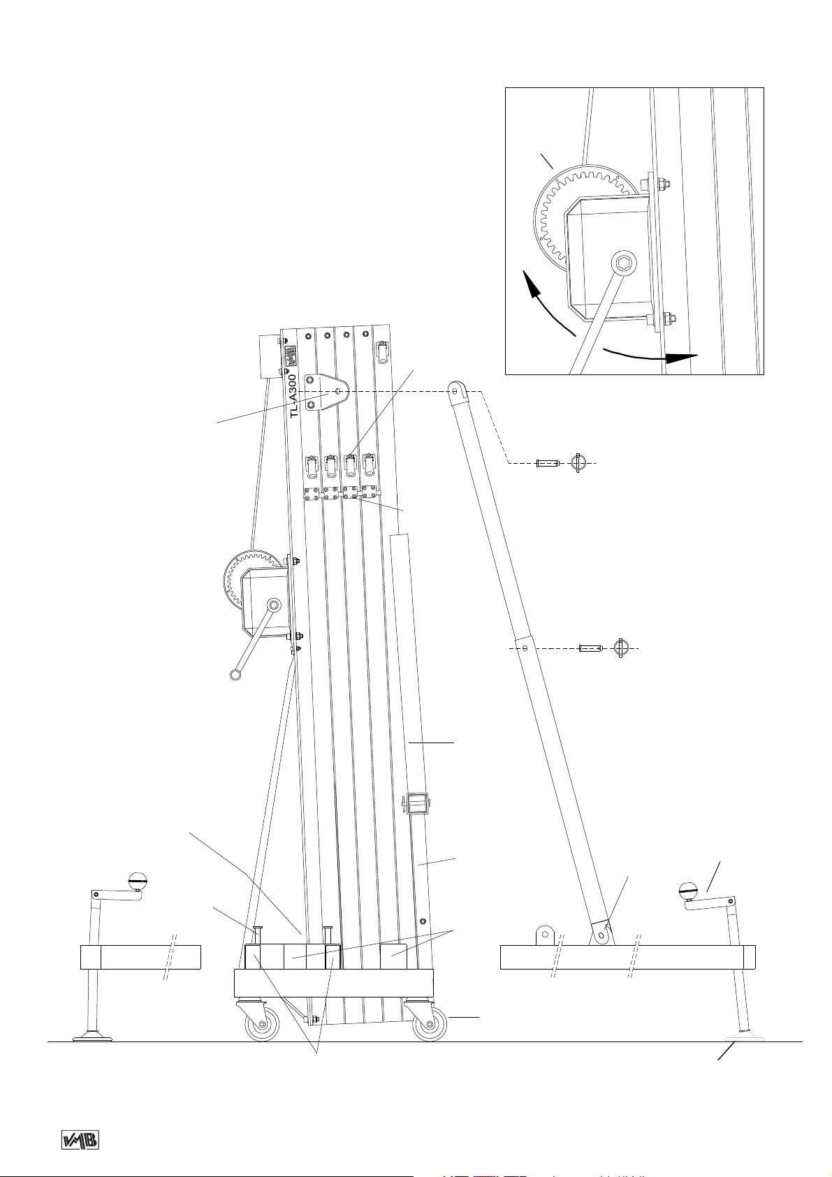
4. INSTRUCTIONS.
4.1– Situate the lift on its transport wheels (T)
upon a flat and stable surface.
When erecting the lift in open air, the risk of
wind is prevalent.
Where wind speeds exceed 30 Km/h it is
essential to tie the lift.
4.2 – Remove the outriggers from their
transport compartments (B) and place them
in the working position (V) ensuring they are
fixed with the security locks (R). The long
outriggers are placed at the front beneath the
load. The short outriggers are placed at the
back.
4.3 – Extend the front telescopic support bars
(BA) from their position on the outrigger (D)
and place them in the top of the first profile (E)
ensuring they are fixed with the pins provided
BU/P1 at the top, bottom and in the central
hole where extended.
Adjust the vertical position of the lift with the
stabilisers (Q) turning the handels so that the
spirit level is centred (F).
4.4 – Remove the forks and place them
horizontally and place the lifting carriage at the
required height so that the Line Array bumper
can be attached.
The wide positioning of the front outriggers
enables the LineArray to fit between them and
eases assembley on to the forks.
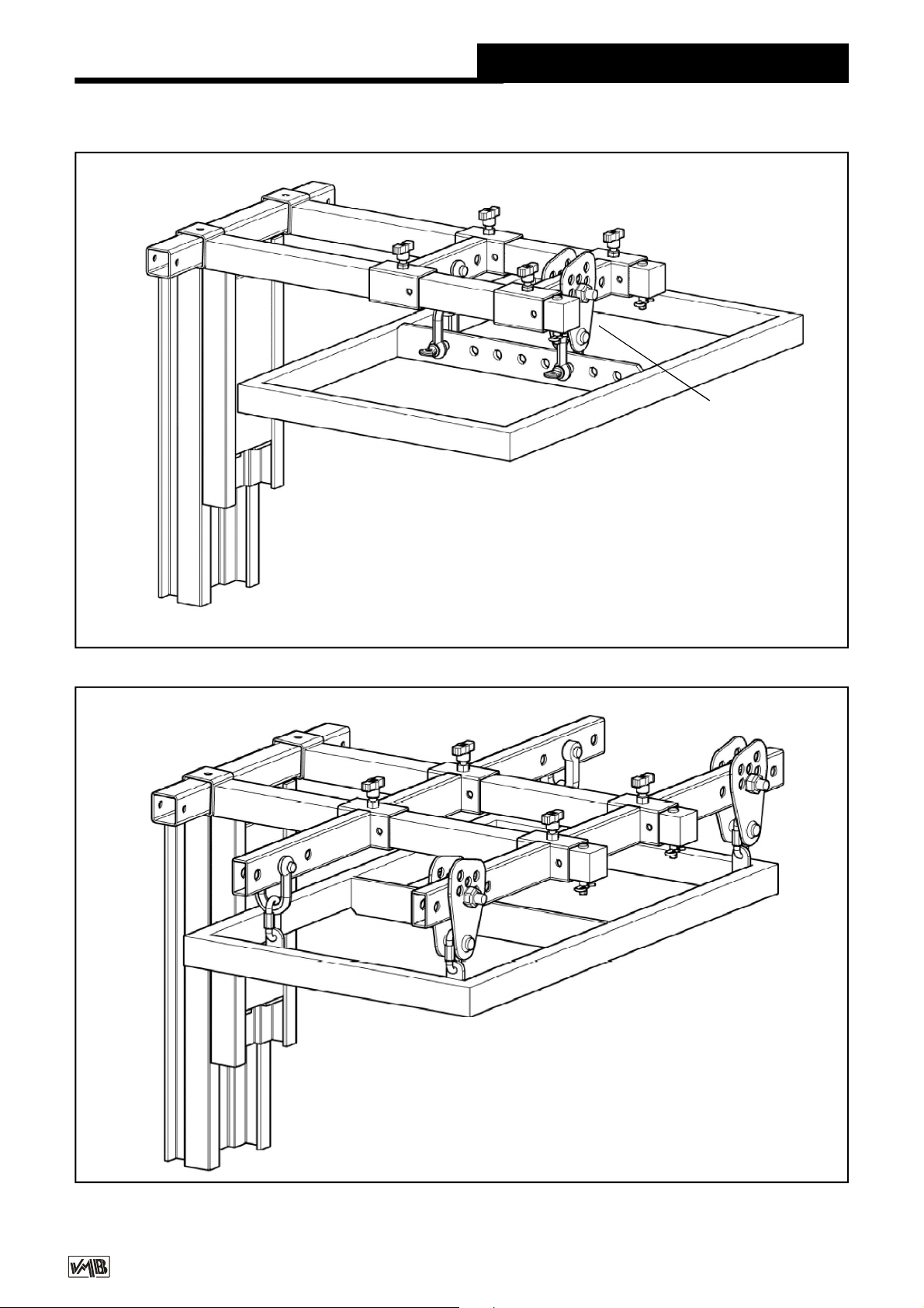
Support FAS-01 is to be fixed to the forks by
either 1 or 2 points. See fig. 1.
If the Line Array Bumper has 4 link points use
the FAS-02 support which enables the Line
Array to be flown from 4 points, see fig. 2.
Both supports FAS-01 and FAS-02 are inserted
on the forks as follows:
The Line Array cabinets will be attached to their
bumper with the angles calculated according
to the acoustic coverage required.
This ensures the Line Array cabinets can be
curved in function with the necessary degrees
required between them.
The system should be attached at the
necessary distance to achieve the required
curve. The last cabinet should not hit the body
of the lift. See fig. 3.
To ensure the maximum security margin it is
necessarry to always attach the Line Array at
the minimum distance possible from the body
of the lift. This will mean that the bottom cabinet
is as close as possible to the body of the lift.
See fig. 3A.
To avoid overloading do not seperate
uneccessarily the Line Array from the body of
the lift. See fig. 3B.
Quick Operation Guide ENGLISH
v12.03 - Depósito legal y Copyright 2012. Todos los derechos reservados.
PRO L IFTS S.L.
Quick Operation Guide ENGLISH
Fig. 2
Fig. 1
FAS-01
FAS-02 PR-01
PR-01

v12.03 - Depósito legal y Copyright 2012. Todos los derechos reservados.
PRO L IFTS S.L.
Quick Operation Guide ENGLISH
FAS-01
BC-075L
FAS-02
MR-PAS
MO-30
GS-0,8
PAT-01
PR-01
MR-SPI PAS-SPI
Fig. 3
TL-A300TL-A300
Fig. 4

v12.03 - Depósito legal y Copyright 2012. Todos los derechos reservados.
PRO L IFTS S.L.
Quick Operation Guide ENGLISH
4.5 – The maximum load of the TL-A300 is
300 Kg with the load point at 50 cm from the
lift’s body.
The loading point capacity can be found on
the vertical line which marks the centre of
gravity of the Line Array which is to be flow.
The situation of the centre of gravity
depends upon the chosen Line Array and is
necessary to calculate before use. Never the
less, it is usually situated at the centre of the
Line Array.
See example Fig. 5B; 5 Lynx Pro Audio LX-
V8 cabinets with a total of 266 Kg.
Never overload the lift above the stated
maximum weight of 300 Kg. See Fig. 5.
Fig. 6
LOAD SPECIFICATIONS
Fig. 5
FRONTAL LIFT VS STANDARD LIFT
Centred load distance
to the lifting carriage
50 cm 219 kg 300 Kg
60 cm 193 kg 250 Kg
Load
DISTANCE
Max.Load
TL-075
Max.Load
TL-A300
Comparison between TL-A300 and a standard
lift TL-075
With 300 Kg of maximum load capacity, the
TL-075 loses a lot of its capacity when we
move the load from the main body of the lift.
This is valid for any standard lift.
60 cm
65 cm
55 cm
50 cm
TL-A300
Fig. 5B
TL-A300
LYNX (266 Kg)
50 cm
v12.03 - Depósito legal y Copyright 2012. Todos los derechos reservados.
PRO L IFTS S.L.
4.6 – The TL-A300, can also be used as a
conventional towerlift.
If you are using it as a conventional towerlift
always place the load as close to the body as
possible. In all frontal load towerlifts the
maximum load is reduced the further away
from the body the load is placed.
See load table opposite indicating distance of
centred load for a TL-075 towerlift. (Fig. 6)
4.7 – Elevating the lift:
Once the Line Array is attached to its bumper
and in the desired position on the forks it is
ready to be lifted to the required height. Turn
the winch handle in a clockwise direction to
elevate the lift.
First, the lifting carriage with the attached Line
Array will raise. When it has reached the top
then the profile will start to rise.
The ILS and ALS enable the lift to rise and
automatically block the carriage and profiles
whilst rising ensuring that it will never fall. The
lift, with the Line array attached will remain fixed
at all times. The SRS (Sequence-Retainer-
System) will also ensure that the profiles rise
in sequence, one after the other.
Once the system is elevated to its required
height gently turn the handle in a clockwise
direction. The security systems will ensure that
the load stays fixed and blocked. The red ALS
locks will be blocked. This enables the cable
to be without any force and means it is only
used for the elevation and descent of the lift.
The following instructions will help you to bring
the system down.
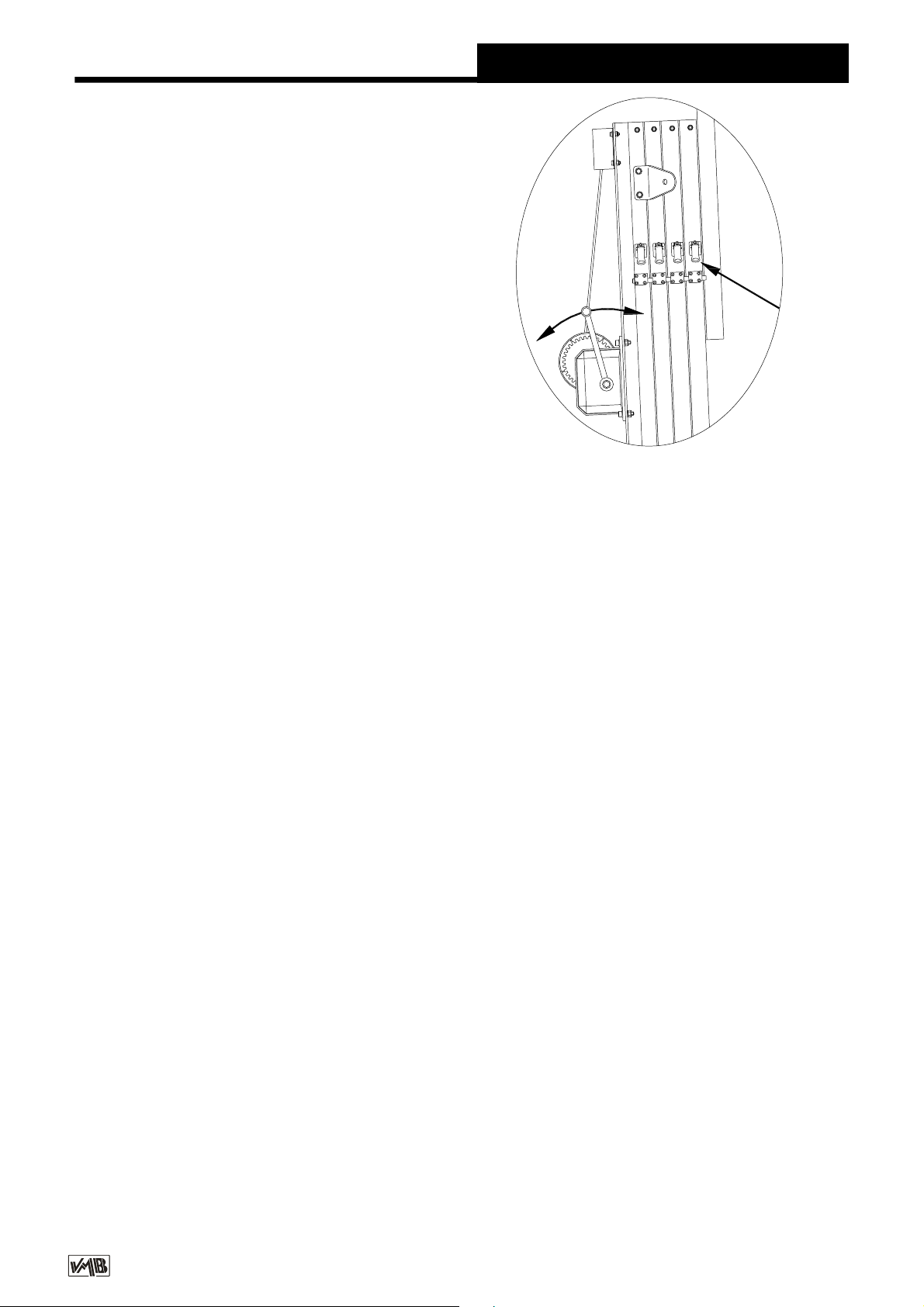
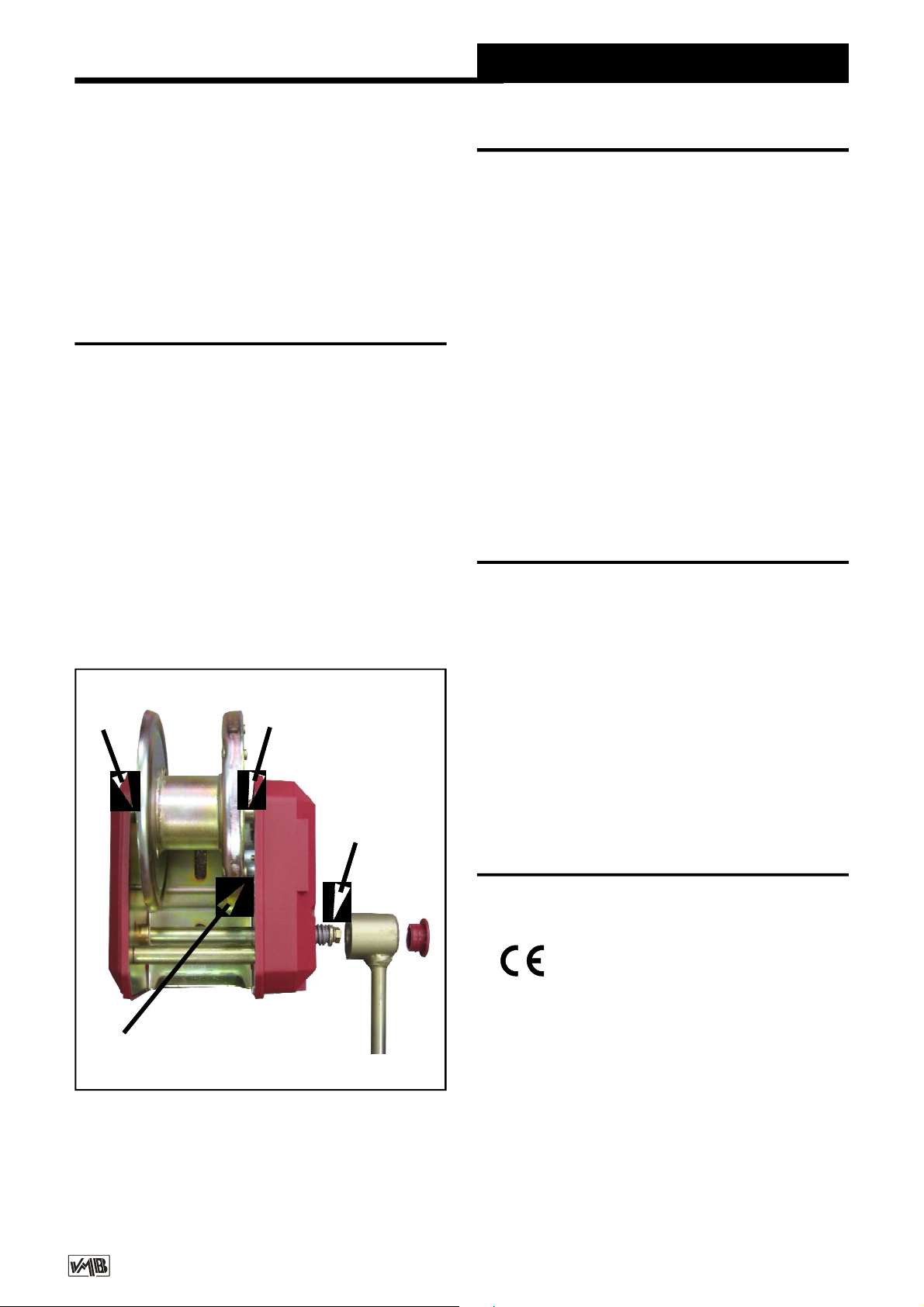
4.8 – Descending the lift:
To bring the lift down you need to first turn the
winch handle slightly clockwise and at the
same time pull the red ALS lock out (G). (Fig.
7)
This releases the blocking systems. Then turn
the handle anti clockwise, whilst maintaining
the
ALS lock pulled out until the profile has been
completely lowered.
All red ALS locks should be pulled out one by
one whilst the handle is turned anti clockwise
and the profiles are brought down, one by one.
If you release your finger from the ALS lock it
will automatically block. In this case, repeat
the first operation by turning slightly clockwise
and then anti clockwise whilst always pulling
the red ALS lock out.
It is necessary to completely lower each profile
before starting to lower the next. If you pull
another red ALS lock without having
completely lowered the previous profile the first
profile will remain blocked by the security
system and you will not be able to lower it later.
If this happens, elevate the towerlift to the
locked position and free the lock so that you
can commence the descent again until it is
completely lowered.
Finally, release the carriage lock following the
same principle as before and lower it to the
required level to be able to dismount the Line
Array from the lift.
Quick Operation Guide ENGLISH
Fig. 7
4.9 – Transport
Once all the profiles are completely lowered
remove the FAS-01 or FAS-02 support and the
forks placing them in their horizontal position
facing down and lower the carriage.
G
v12.03 - Depósito legal y Copyright 2012. Todos los derechos reservados.
PRO L IFTS S.L.
5. MAINTENANCE.
5.1 – Periodically check the condition of the
cable. If a cable is torn or broken it should be
replaced immediately. Do not use the lift if the
cable is not perfect. Only use torsion resistant
steel cable DIN 3060.
5.2 – The lift is supplied completely greased
from the factory. Never the less, we
recommend you periodically grease
(depending on amount used) the teeth of the
winch (CD), end point of the handle (RM), bar
(EB) (Fig. 8) and the profile nylon drums.
ATTENTION: Do not grease or lubricate the
break mechanism.
The brake discs have been greased with a
special heat and pressure resistant grease. Do
not use other products.
Quick Operation Guide ENGLISH
7. CERTIFICATIONS
-
EC Machinery Directive
89/392/ECC and 98/37/ECC
- BGV C1 (GUV-VC1) / BGG 912 (GUV-G912)
6. GUARANTEE.
The warranty period for this lift is 2 years from
the date of purchase.
PRO LIFTS S.L. promises, that from the date
of purchase and during the warranty period to
resolve any faults that may occur produced
through defect material or fabrication.
Damage caused by inproper use, product
modification, terciary manipulation or acciden-
tal fire are not covered by this warranty.
5.3 – All lifts should undergo an annual
technical inspection carried out by an
authorized VMB dealer to check the
certifications and general condition of all the
lift’s elements and security systems involved
in the lift’s use.
5.4 – Only use original spare parts to guarantee
a continued security level.
The user loses all rights to warranty if any spare
parts other than originals are used or carries
out any modification or alteration to the
towerlift.
5.5 – To request a spare part please indicate
the corresponding code which can be found in
this manual.
Remove the front telescopic support bars (BA)
by taking out the pins (BU/P1) ,un-extend and
place in the two transport positions located on
the outriggers. Place the outiggers in their
transport houses (B).
EB EB
CD
RM
Figura 8

v12.03 - Depósito legal y Copyright 2012. Todos los derechos reservados.
PRO L IFTS S.L.
Manual de instrucciones ESPAÑOL
CONTENIDO
1. Introducción
2. Datos técnicos
3. Normas de seguridad
4. Instrucciones de uso
5. Mantenimiento
6. Garantía
7. Certificaciones
1. INTRODUCCION
Estimado usuario:
Agradecemos su confianza al adquirir las
torres elevadoras VMB.
Tiene en sus manos un producto de calidad y
fiabilidad contrastadas por la dilatada
experiencia de los usuarios profesionales en
todo el mundo.
Para poder trabajar con este elevador volando
todo tipo de equipos de sonido sin peligro y
de forma segura, lea atentamente este
manual, observe los datos técnicos y siga
íntegramente todas las instrucciones de
utilización y seguridad.
Este manual de instrucciones, deberá estar
disponible permanentemente junto al elevador.
Todos los elevadores VMB son sometidos a
un constante control de calidad y durísimas
pruebas de verificación, para garantizar la
máxima fiabilidad y resistencia.
El elevador TL-A300, ha sido proyectado
especialmente para levantar hasta 5.8 metros
de altura, equipos de sonido tipo line array con
un peso de 300 Kg desplazados 50 cm. en
avance respecto al cuerpo de la torre.
Este desplazamiento, es necesario para poder
angular los recintos acústicos los grados
precisos para lograr una perfecta cobertura de
sonorización.
2. DATOS TÉCNICOS
2.1 - Torre elevadora modelo TL-A300.
2.2 - Diseñada especialmente para levantar
equipos de sonido tipo line array desde el
mismo suelo en sentido vertical a cualquier
altura hasta 5.8 m., con un avance respecto
al cuerpo de la torre de 50 cm.
2.3 - Carga máxima elevable: 300 Kg.
desplazada 50 cm del cuerpo del elevador.
2.4 - Carga mínima elevable: Puede subir o
bajar sin carga alguna.
2.5 - Altura máxima: 5.8 m.
2.6 - Altura plegada: 1,58 m. Altura mínima
de carga : 0,05 m.
2.7 - Superficie de la base : 1,9 x 2,1 m.
El elevador, TL-A300, incorpora los sistemas
de seguridad ALS (Automatic-Lock-Security),
ILS (Inertia-Lock-Securyty) exclusivos de
VMB, que garantizan la imposibilidad de caida
de la carga y una total seguridad de
utilización.Tambien incluye el SRS system
(Sistema de Retención) que permite que los
tramos suban progresivamente.
ATENCION:
No utilice este elevador sin haber leído y seguir
estas instrucciones. En caso contrario, podría
llegar a provocar un grave accidente.
Durante la vida útil del elevador, puede
necesitar piezas de repuesto. Diríjase en este
caso a su distribuidor habitual.
Solamente deben utilizarse piezas de repuesto
originales. El usuario perderá todos sus
derechos de garantía si incorpora cualquier
repuesto que no sea original o realiza cualquier
modificación en el elevador.
Para cualquier consulta sobre el elevador,
deberá indicar el número de serie y año de
construcción.
v12.03 - Depósito legal y Copyright 2012. Todos los derechos reservados.
PRO L IFTS S.L.
2.8 - Peso de transporte : 165 Kg.
2.9 - Material de construcción: Cuerpo
principal de cuatro tramos más carro
elevador, en perfil de aluminio extrusionado
6082-T6. Base, patas y soportes varios, en
perfileria de acero según DIN 2394. Gatillos
de seguridad y poleas acanaladas en acero
ST-37.
2.10 - Sistemas de fijación, seguridad ALS
(Automatic-Lock-Security), ILS (Inertia-
Lock-Securyty) que fijan e imposibilitan la
caida de la carga en todo momento.
2.11 - Cabrestante de acción manual de
900Kg de capacidad de carga máxima con
freno de discos automático.
Manual de instrucciones ESPAÑOL
2.12 - Cable : Acero según DIN 3060. Calidad
180 Kg/mm2antitorsión. Diámetro 6 mm.
2.13 - Platillos estabilizadores ajustables en
las patas, con apoyos antideslizantes de
caucho inyectado.
2.14 - Fijación de las patas con gatillos de
seguridad.
2.15 - Nivel de burbuja para ajustar la posición
vertical de la torre.
2.16 - Todos los elementos del elevador están
acabados en poliéster negro satinado.
2.17 - Ruedas direccionables para facilitar el
transporte de la torre en posición vertical y
plegada hasta su emplazamiento de trabajo.
3. NORMAS DE SEGURIDAD.
3.1 - El elevador TL-A300 es una máquina
diseñada para la elevación de cargas en
sentido vertical, NUNCA se debe utilizar
como plataforma elevadora de personas.
3.2 - Colocar elelevadorsóloensuperficies
duras y planas, verificando que está en
posición vertical, mediante el nivel de
burbuja (F) situado en el tramo base.
Ajustar si fuera necesario con los platillos
de apoyo (Q), girando la manivela (H) en
el sentido adecuado. Nunca utilice cuñas
ni elementos extraños para equilibrar el
elevador.
!
v12.03 - Depósito legal y Copyright 2012. Todos los derechos reservados.
PRO L IFTS S.L.
Manual de instrucciones ESPAÑOL
3.5 - No se debe sobrepasar la capacidad
de carga máxima indicada en la etiqueta
de características del elevador y en este
manual de instrucciones.
3.4 - Nunca se debe elevar una carga
sin antes verificar que está correctamente
apoyada y centrada en los soportes
elevadores adecuados, de forma que el
peso de la carga sólo actúe en sentido
vertical.
3.3 - Comprobar que las patas están
correctamente montadas y sujetas por sus
pasadores retenedores de seguridad.
Kgs
3.6 - Si existe posibilidad de viento fuerte o
en ráfagas, coloque el elevador en suelo
firme y asegúrelo con la ayuda de tirantes.
Nunca fije un tirante sobre un vehículo
o cualquier otro elemento que pueda
desplazarse.
3.7 - No use escaleras encima del elevador
ni las apoye en él para realizar ningún tipo
de trabajo.

v12.03 - Depósito legal y Copyright 2012. Todos los derechos reservados.
PRO L IFTS S.L.
Manual de instrucciones ESPAÑOL
3.11 - No utilice nunca el elevador sobre
una superficie móvil o vehículo.
3.10 - No desplace nunca el elevador si se
encuentra con la carga elevada. No es
aconsejable realizar ningún tipo de
movimiento, ni tan siquiera pequeños
ajustes de posicionamiento.
3.9 - Nunca se ponga debajo de la carga ni
permita la presencia de otras personas en
la zona de trabajo del elevador.
3.8 - Tenga cuidado con todo tipo de
salientes por encima del elevador como
cornisas, balcones, letreros luminosos,
etc...
Es muy importante evitar la presencia de
cables por debajo de la altura de trabajo
del elevador.
3.12 - Antesdeutilizarelelevador,verifique
el estado del cable. El cable no debe
presentar rotura de hilos o aplastamiento.
NUNCA use cables defectuosos yen caso
de duda cambie el cable. Sólo utilice cable
de acero según DIN 3060. Calidad 180 Kg/
mm2resistente a la torsión.

v12.03 - Depósito legal y Copyright 2012. Todos los derechos reservados.
PRO L IFTS S.L.
3.16 - Para el transporte del elevador hay
que bajar todos los tramos.
3.15 - No engrase ni lubrique el mecanis-
mo de freno del cabrestante. Los discos de
freno, han sido engrasados con una grasa
especial resistente al calor y la presión.
No deben ser utilizados otros productos
para evitar influir negativamente en el
funcionamiento del freno.
3.14 - La carga mínima para el funciona-
miento del freno del cabrestante sin pro-
blemas, es de 25Kg.Sin esta carga mínima
el freno podría no actuar.
3.13 - Nunca desmonte la manivela del
cabrestante si el elevador está con carga y
elevado.
3.17 - Solamente deben utilizarse piezas
de repuesto originales.
Manual de instrucciones ESPAÑOL
-25
OR IGINAL

v12.03 - Depósito legal y Copyright 2012. Todos los derechos reservados.
PRO L IFTS S.L.
4. INSTRUCCIONES DE USO.
4.1 - Coloque la torre elevadora apoyada en
sus ruedas de transporte (T) en su
emplazamiento de trabajo sobre una superficie
plana y firme.
En el caso de montar el elevador al aire libre,
existe el riesgo que durante su utilización se
genere viento.
A partir de una velocidad del viento de 30 Km/
h es imprescindible arriostrar el elevador.
4.2 - Saque las patas de su soporte para
transporte (B) e insértelas a fondo en sus
alojamientos de trabajo (V) comprobando que
quedan sujetas por los gatillos retenedores (R).
Las patas largas delante, bajo la carga y las
cortas detrás .
4.3 - Saque los brazos de apoyo frontales
telescópicos (BA) alojados en las patas,
despliéguelos y colóquelos en sus puntos de
anclaje (D) fijando el pasador en el agujero
central sobre cada pata delantera y en los
laterales de la parte superior del tramo base
(E), fijándolos con los pasadores de seguridad
(BU/P1).
Sobre los brazos de carga, se colocarán los
soportes FAS-01, en el caso de volar un equipo
con fijación central por uno o dos puntos de
vuelo, fig. 1.
En el caso de que el soporte de volado del
equipo de sonido tenga cuatro anclajes
perimetrales, se utilizarán los soportes FAS-
02 que permiten suspender los soportes de
volado desde cuatro puntos, ver fig. 2.
Tanto los soportes FAS-01 como los FAS-02
se colocarán sobre los brazos de carga en la
posición y forma que se indica seguidamente:
Los recintos acústicos del equipo de sonido,
se montarán sobre su soporte de volado con
las angulaciones calculadas para la cobertura
acústica requerida.
Esto condiciona que los recintos de line array
se curvarán hacia detrás en función de los
grados necesarios entre ellos.
El equipo deberá colocarse en consecuencia
sobre los brazos de carga del elevador con el
avance necesario para conseguir que esta
curvatura pueda realizarse, sin que la parte
trasera inferior del último recinto tropiece con
el cuerpo del elevador. Ver fig. 3.
Para conseguir el máximo margen de
seguridad, es necesario colocar siempre el
equipo de sonido sobre los brazos de carga
del elevador con el avance mínimo posible,
de forma que la parte trasera inferior del último
recinto del equipo line array se encuentre lo
más cerca posible del cuerpo de la torre. Ver
fig. 3A.
No separar innecesariamente el equipo de
sonido del cuerpo de la torre para evitar una
sobrecarga. Ver fig. 3B.
Manual de instrucciones ESPAÑOL
4.4 - Soltar el seguro de transporte B , sacar
los brazos de carga y volver a colocarlos en
posición horizontal.
Colocar el carro elevador a la altura necesaria
para poder fijar el soporte de volado del equipo
de line array.
La especial disposición de las patas
delanteras, permite situar el equipo de sonido
en el suelo justo bajo los brazos de carga.
Other manuals for TL-A300
2
Table of contents
Languages:
Other VMB Lifting System manuals

VMB
VMB TE-074 User manual

VMB
VMB TL - 075C User guide

VMB
VMB TL-054 Instruction Manual

VMB
VMB TE-034 User manual

VMB
VMB TE-071 Instruction Manual

VMB
VMB TE-064 Instruction Manual

VMB
VMB TL-A220 User manual

VMB
VMB Pro Lifts TL-063 Instruction Manual

VMB
VMB TL-A450 Instruction Manual

VMB
VMB TE-074PB User manual


Popular Lifting System manuals by other brands


Pro-Lift
Pro-Lift C-2036 Operating instructions & parts manual

Tractel
Tractel Supertirfor TU16H Operation and maintenance manual

Nova Technology International, LLC
Nova Technology International, LLC NAS Series Owner & user manual

HAMACO
HAMACO ML-150-45V-D12 user manual

MPH
MPH DRXmulti user guide

nifty
nifty TM34M ECO Series Operating and safety instructions


