VS 31506 User manual

VS Vereinigte Spezialmöbelfabriken GmbH & Co.KG
http://links.vs-service.com/downloads/70-335_V03_DEEN_PantoMove-LuPo-Export-141540.pdf
31505 31506 3158031507
Bestimmung
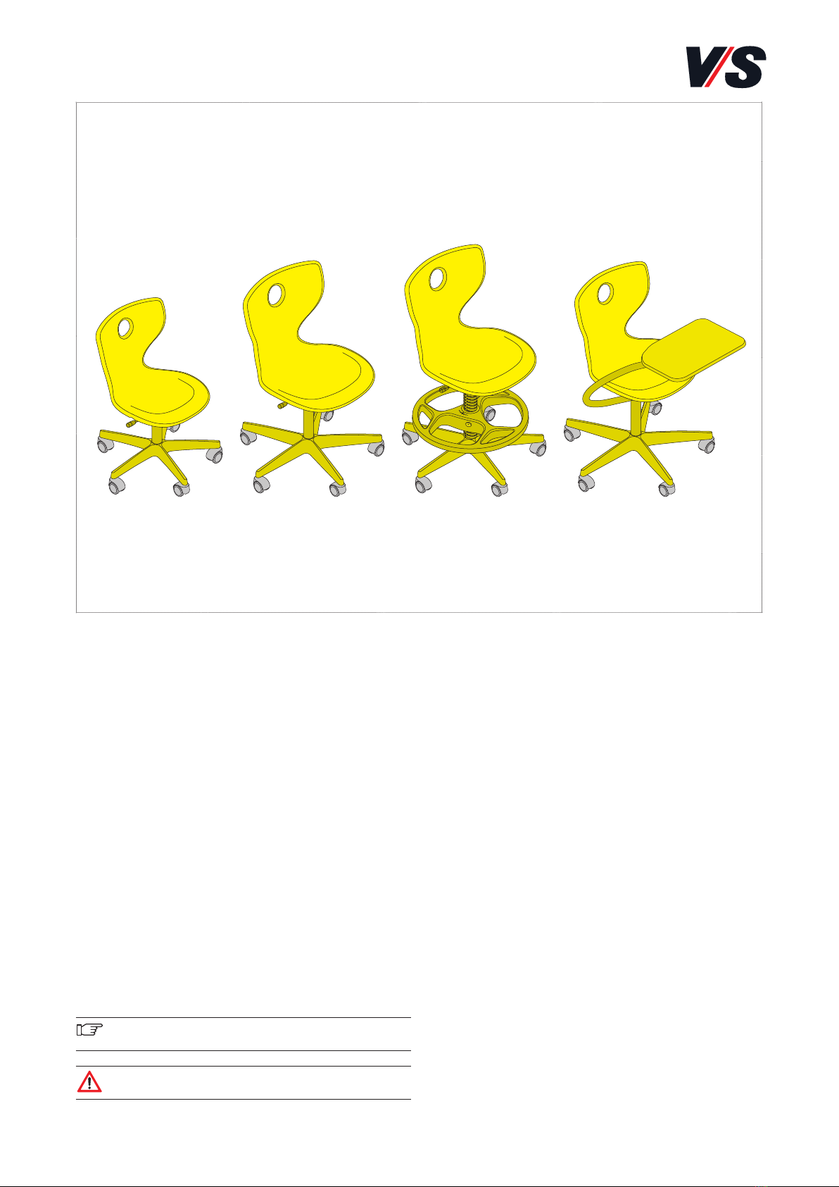
Die Stühle PantoMove-LuPo Export (Modelle 31505-31507,
31580) sind für Bildungseinrichtungen konzipiert und aus-
schließlich für den Einsatz in geschlossenen Räumen geeig-
net. Für eine nicht bestimmungsgemäße Nutzung (z.B. in
Werkstätten, Lager- oder Feuchträumen) wird keine Haftung
übernommen.
Allgemeine Hinweise
Lesen Sie diese Anleitung sowie die Anleitung der Einbau-
teile vor Benutzung der Produkte sorgfältig und beachten
Sie insbesondere auch die Sicherheitshinweise. Bewahren
Sie die Anleitung zum späteren Nachlesen auf bzw. geben
Sie diese an andere Benutzer weiter.
Allgemeine Sicherheitshinweise
In unseren Bedienanleitungen verwenden wir folgende
Symbole und Hinweise:
Wichtig! Bei diesem Symbol handelt es sich um einen
wichtigen Montagehinweis.
Achtung! Bei diesem Symbol handelt es sich um einen
sehr wichtigen Hinweis.
Im Internet
Diese Anleitung wird Ihnen online über den in der Kopfleiste
angegeben Link als Download bereitgestellt.
Prüfnormen
Geprüft nach DIN EN 1729 - 1/2.
Lieferumfang
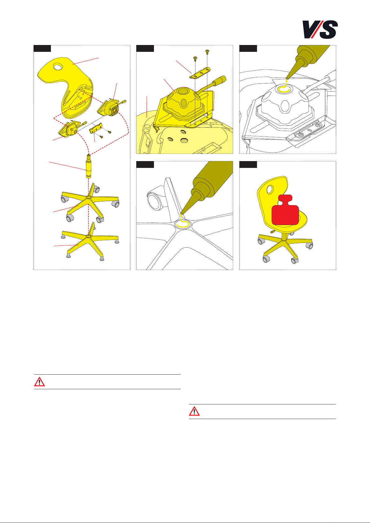
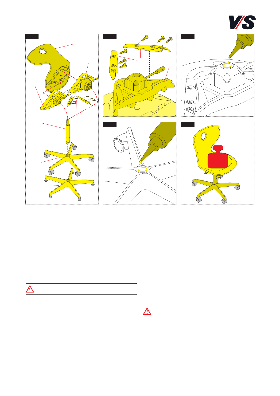
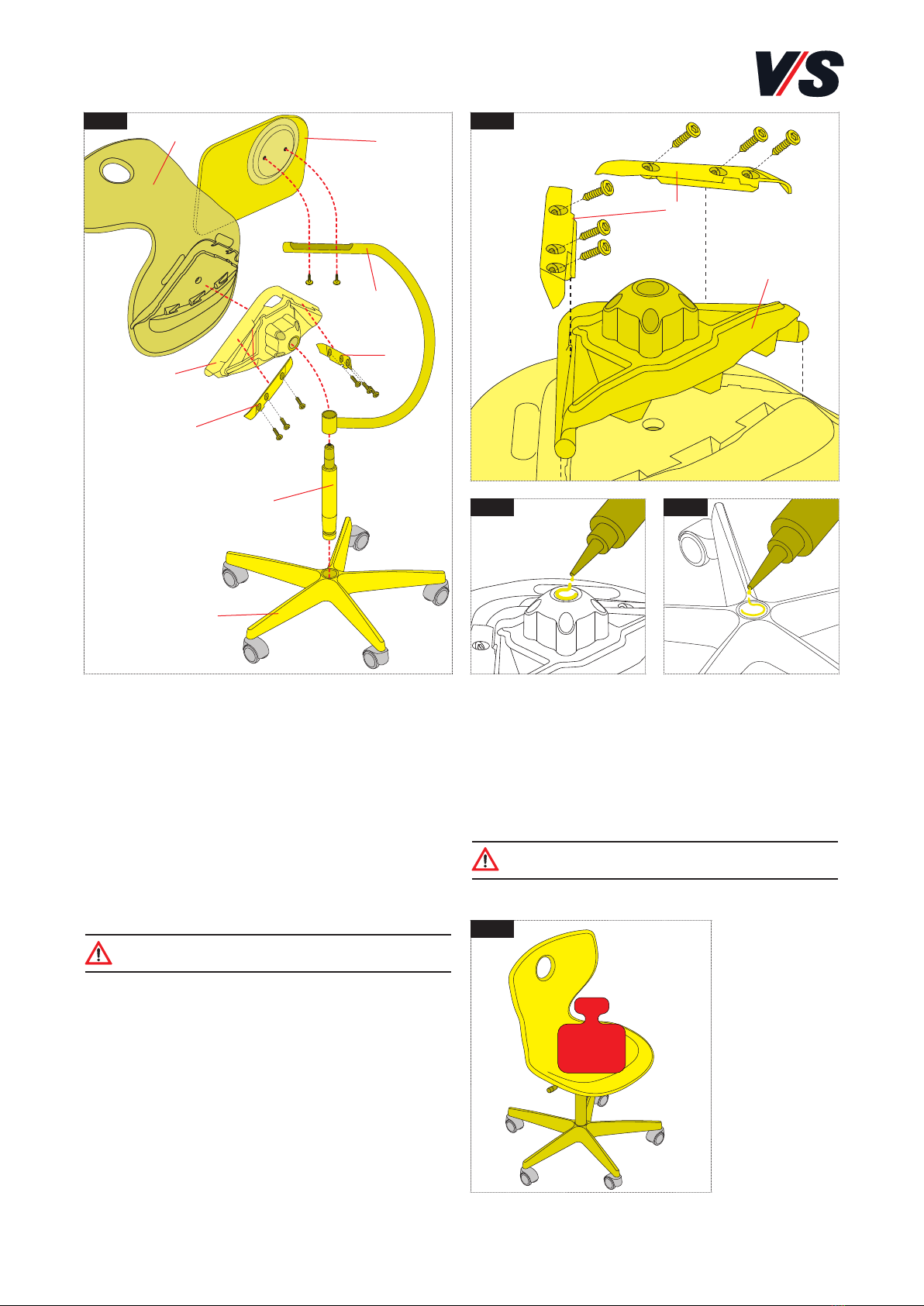
Die Produkte werden teilmontiert ausgeliefert.
Betrieb
Beachten Sie die Hinweise auf den folgenden Seiten.
Fehlersuche und Service
Bei eventuell auftretenden Fehlern wenden Sie sich bitte
Wartung und Reinigung
Mehr dazu: vs.de/kataloge/reinigung/
Weitergabe
Achten Sie darauf, bei einer Weitergabe des Produkts auch
diese Anleitung mit zu übergeben. Für eine umweltgerechte
Entsorgung informieren Sie sich bei Ihrer Kommune.
MONTAGEANLEITUNG 70-335 V03 000617
PantoMove-LuPo Export.
Modelle 31505-31507, 31580.

2
1
(2.2)
(2.1)
(5.1)
(5.2)
(1)
(3)
(1)
(2)
(3)
(4)
400 N
2 3
4 5
Modell 31505 (Bild 1)
Komponenten:
- Sitzschale (1)
- Sitzträger - starr (2.1)
- mit 3D-Wippe (2.2)
- Befestigungsmaterial - Lasche mit 2 Schrauben M5x13
(3)
- Gasfeder (4)
- Fußkreuz, vormontiert mit Rollen (5.1)
- Fußkreuz mit Gleitern (5.2)
- Kleber (ohne Bild)
Achtung! Die Komponenten der verschiedenen
Stühle dürfen nicht untereinander getauscht werden.
Vorbereitung der Montage
Gasfeder (4) am oberen Konus mit geeignetem Reiniger
entfetten.
Verbindung Sitzschale und Sitzträger
(Bild 2)
Sitzträger (2) auf Sitzschale (1) stecken und mit der
beigefügten Lasche (3) und den Schrauben verbinden.
Montage der Stuhlkomponenten
(Bild 3/4/5)
Konus des Sitzträgers (Bild 3) und des Fußkreuzes (Bild 4)
reinigen. An beiden Positionen jeweils auf ca. 4-5 cm Länge
den beigefügten Kleber auftragen.
Die Teile zusammenfügen und die Sitzfläche mindestens
5 Sekunden mit 400 N belasten (Bild 5).
Achtung! Der Kleber muss gut aushärten.
Der Stuhl ist erst nach 24 Stunden voll belastbar.

400 N
3
1 2 3
4 5
(2.2)
(2.1)
(5.1)
(5.2)
(2)
(4)
(1)
(1)
(3)
(3)
Modell 31506 (Bild 1)
Komponenten:
- Sitzschale (1)
- Sitzträger - starr (2.1)
- mit 3D-Wippe (2.2)
- Befestigungsmaterial - 2 Laschen mit 6 Schrauben
M5x25 (3)
- Gasfeder (4)
- Fußkreuz, vormontiert mit Rollen (5.1)
- Fußkreuz mit Gleitern (5.2)
- Kleber (ohne Bild)
Achtung! Die Komponenten der verschiedenen
Stühle dürfen nicht untereinander getauscht werden.
Vorbereitung der Montage
Gasfeder (4) am oberen Konus mit geeignetem Reiniger
entfetten.
Verbindung Sitzschale und Sitzträger
(Bild 2)
Sitzträger (2) auf Sitzschale (1) stecken und mit den
beigefügten Laschen (3) und den Schrauben verbinden.
Montage der Stuhlkomponenten
(Bild 3/4/5)
Konus des Sitzträgers (Bild 3) und des Fußkreuzes (Bild 4)
reinigen. An beiden Positionen jeweils auf ca. 4-5 cm Länge
den beigefügten Kleber auftragen.
Die Teile zusammenfügen und die Sitzfläche mindestens
5 Sekunden mit 400 N belasten (Bild 5).
Achtung! Der Kleber muss gut aushärten.
Der Stuhl ist erst nach 24 Stunden voll belastbar.

4
1 2
(2.2)
(2.1)
(7.1)
(7.2)
(2)
(4)
(5)
(1)
(1)
(3)
(6)
Modell 31507 [Bild 1]
Komponenten:
- Sitzschale (1)
- Sitzträger - starr (2.1)
- mit 3D-Wippe (2.2)
- Befestigungsmaterial - 2 Laschen mit 6 Schrauben
M5x25 (3)
- Fußring (4)
- Gasfeder mit Führungsrohr (5)
- Adapter (6)
- Fußkreuz, vormontiert mit Rollen (7.1)
- Fußkreuz mit Gleitern (7.2)
- Kleber (ohne Bild)
Achtung! Die Komponenten der verschiedenen
Stühle dürfen nicht untereinander getauscht werden.
Verbindung Sitzschale und Sitzträger
[Bild 2]
Sitzträger (2) auf Sitzschale (1) stecken und mit den
beigefügten Laschen (3) und den Schrauben verbinden.

(4)
(8)
5
(9)
3 4 5
1
(6)
(5)
21.1 2.1
(6)
400 N
6
Montage der Stuhlkomponenten
[Bild 4/5/6]
Gasfeder (5) am oberen Konus mit geeignetem Reiniger
entfetten. Konus des Sitzträgers [Bild 4] und des Fußkreuzes
[Bild 5] reinigen. An beiden Positionen jeweils auf ca. 4-5 cm
Länge den beigefügten Kleber auftragen.
Die Teile zusammenfügen und die Sitzfläche mindestens
5 Sekunden mit 400 N belasten) [Bild 6].
Achtung! Der Kleber muss gut aushärten.
Der Stuhl ist erst nach 24 Stunden voll belastbar.
Gasfeder und Adapter vormontieren
[Bild 1]
Gasfeder (5) in Vorrichtung stellen und ausrichten. Adapter-
hälften (6) ansetzen. Dabei muss die Führungsnut der Gas-
feder im Schlitz des Adapters sichtbar sein und die Ober-
kante des Adapters mit dem obersten Loch der Führungsnut
abschließen [Bild 1.1].
Gasfeder und Fußring vormontieren
[Bild 2]
Gasfeder mit Adapter in Vorrichtung setzen und Fußring (4)
aufstecken. Dabei ist der Knopf (8) gedrückt zu halten.
Achtung! Die Markierung auf dem Ring oben muss
in Richtung der Führungsnut zeigen [Bild 2.1].
Der Fußring wird mit 1-2 Hammerschlägen auf ein Überrohr
(9) soweit über den Adapter geschoben bis er einrastet.
Achtung! Die Unterseite dieser Baugruppe ist zu kon-
trollieren! Zwischen Fußring und Adapter muss ein
Versatz sein [Bild 3]. Andernfalls muss der Fußring
noch weiter auf den Adapter geschoben werden.

6
400 N
1 2
3 4
5
(5)
(3)
(6)
(7)
(2)
(2)
(1)
(1)
(3)
(3)
(4)
Modell 31580 [Bild 1]
Komponenten:
- Sitzschale (1)
- Sitzträger starr (2)
- Befestigungsmaterial - 2 Laschen mit 6 Schrauben
M5x25 (3)
- Tragearm (4)
- Tablar (5) mit Drehteller und 2 Schrauben M5x25
- Gasfeder (6)
- Fußkreuz (7), vormontiert mit Rollen oder Gleitern
- Kleber (ohne Bild)
Achtung! Die Komponenten der verschiedenen
Stühle dürfen nicht untereinander getauscht werden.
Vorbereitung der Montage
Gasfeder (6) am oberen Konus mit geeignetem Reiniger
entfetten.
Verbindung Sitzschale und Sitzträger
[Bild 2]
Sitzträger (2) auf Sitzschale (1) stecken und mit den
beigefügten Laschen (3) und Schrauben fest verbinden.
Montage des Tablars [Bild 1]
Buchse des Tragarms (4) auf den oberen Konus der Gasfeder
(6) stecken. Den Drehteller (5) auf der Unterseite des Ta-
blars (4) mit 2 Schrauben am Tragarm (4) befestigen.
Montage der Stuhlkomponenten
[Bild 3/4/5]
Konus des Sitzträgers [Bild 3] und des Fußkreuzes [Bild 4]
reinigen. An beiden Positionen jeweils auf ca. 4-5 cm Länge
den beigefügten Kleber auftragen.
Die Teile fest zusammenfügen und die Sitzfläche mindes-
tens 5 Sekunden mit 400 N belasten [Bild 5].
Achtung! Der Kleber muss komplett aushärten.
Der Stuhl ist erst nach 24 Stunden voll belastbar.

7
VS Vereinigte Spezialmöbelfabriken GmbH & Co.KG
http://links.vs-service.com/downloads/70-335_V03_DEEN_PantoMove-LuPo-Export-141540.pdf
Intended use:
These chair models have been designed and are suitable for
use in educational establishments. No liability will be for
any use other than that intended, for example in workshops,
storage rooms or damp locations. To be used in closed pre-
mises only.
General note on reading and retaining
these Instructions:
Read these Instructions, the instructions for the associated
assembly parts and, in particular, the safety instructions
before using the products and adhere to these. Keep these
Instructions in a safe place for future consultation and com-
municate them to other users.
General note on safety:
The following symbols and notes are used in our Instructions
for Use:
Important! This symbol indicates an
important assembly note.
Caution! This symbol indicates a very
important note.
On the Web:
You can find these Instructions on the Web.
Standards:
Tested in accordance with DIN EN 1729 - 1/2.
Scope of delivery:
The products are supplied partially assembled.
Use:
Please take account of the notes on the following pages.
Faults and service:
If any faults occur, please contact our
Maintenance and cleaning
On the Internet: vs.de/kataloge/reinigung/en
Product transfer:
If the product is transferred to another party then it must be
accompanied by these Instructions. For information on the
environmentally responsible disposal of the product, please
contact your relevant local authority department.
ASSEMBLY INSTRUCTIONS 70-335 V03 000617
PantoMove-LuPo Export.
Models 31505-31507.
31505 31506 3158031507

8
1
(2.2)
(2.1)
(5.1)
(5.2)
(1)
(3)
(1)
(2)
(3)
(4)
400 N
2 3
4 5
Model 31505 (Figure 1)
Components:
- Seat shell (1)
- Seat support - rigid (2.1)
- with 3D rocker (2.2)
- Fixing material - plate with 2 M5x13 screws (3)
- Gas spring (4)
- Base cross with pre-mounted castors (5.1)
- Base cross with slide elements (5.2)
- Adhesive (not pictured)
Caution! The components must not be swapped
between the different chairs.
Preparing for assembly
Degrease the top cone of the gas spring (4) using a suitable
cleaning agent.
Fixing the seat shell to the seat support
(Figure 2)
Place the seat support (2) on the seat shell (1) and join
together using the supplied plate (3) and screws.
Assembling the chair components
(Figures 3/4/5)
Clean the cone of the seat support (Figure 3) and the base
cross (Figure 4) Apply the supplied adhesive over a length
of approx. 4-5 cm at both points. Join the parts together
and place a load of 400 N on the seating surface for at least
5 seconds (Figure 5).
Caution! The adhesive must dry well. Wait for
24 hours before subjecting the chair to its full load.

9
400 N
1 2 3
4 5
(2.2)
(2.1)
(5.1)
(5.2)
(2)
(4)
(1)
(1)
(3)
(3)
Model 31506 (Figure 1)
Components:
- Seat shell (1)
- Seat support - rigid (2.1)
- with 3D rocker (2.2)
- Fixing material - 2 plates with 6 M5x25 screws (3)
- Gas spring (4)
- Base cross with pre-mounted castors (5.1)
- Base cross with slide elements (5.2)
- Adhesive (not pictured)
Caution! The components must not be swapped
between the different chairs.
Preparing for assembly
Degrease the top cone of the gas spring (4) using a suitable
cleaning agent.
Fixing the seat shell to the seat support
(Figure 2)
Place the seat support (2) on the seat shell (1) and join to-
gether using the supplied plates (3) and screws.
Assembling the chair components
(Figures 3/4/5)
Clean the cone of the seat support (Figure 3) and the base
cross (Figure 4) Apply the supplied adhesive over a length
of approx. 4-5 cm at both points. Join the parts together
and place a load of 400 N on the seating surface for at least
5 seconds (Figure 5).
Caution! The adhesive must dry well. Wait for
24 hours before subjecting the chair to its full load.

10
1 2
(2.2)
(2.1)
(7.1)
(7.2)
(2)
(4)
(5)
(1)
(1)
(3)
(6)
Model 31507 (Figure 1)
Components:
- Seat shell (1)
- Seat support - rigid (2.1)
- with 3D rocker (2.2)
- Fixing material - 2 plates with 6 M5x25 screws (3)
- Foot ring (4)
- Gas spring with guide tube (5)
- Adapter (6)
- Base cross with pre-mounted castors (7.1)
- Base cross with slide elements (7.2)
- Adhesive (not pictured)
Caution! The components must not be swapped
between the different chairs.
Fixing the seat shell to the seat support
(Figure 2)
Place the seat support (2) on the seat shell (1) and join
together using the supplied plates (3) and screws.

11
(4)
(8)
(9)
3 4 5
1
(6)
(5)
21.1 2.1
(6)
400 N
6
Assembling the chair components
(Figures 4/5/6)
Degrease the top cone of the gas spring (5) using a suitable
cleaning agent. Clean the cone of the seat support (Figure
4) and the base cross (Figure 5) Apply the supplied over a
length of approx. 4-5 cm at both points.
Join the parts together and place a load of 400 N on the
seating surface for at least 5 seconds (Figure 6).
Caution! The adhesive must dry well. Wait for
24 hours before subjecting the chair to its full load.
Pre-assembling the gas spring and
adapter (Figure 1)
Place the gas spring (5) in the mechanism and adjust. At-
tach the halves of the adapter (6) When you do this, the
guide groove of the adapter must be visible in the slot in
the adapter and the top edge of the adapter must be level
with the topmost hole in the guide groove (Figure 1.1).
Pre-assembling the gas spring and
foot ring (Figure 2)
Place the gas spring with the adapter in the mechanism and
position the foot ring (4) on it. When doing this, keep but-
ton (8) pressed in.
Caution! The marking on the top of the ring must
point toward the guide groove (Figure 2.1).
The foot ring is pushed over the adapter until it engages
by striking a surrounding tube (9) once or twice with a
hammer.
Caution! It is necessary to check the underside of this
assembly! There must be an offset between the foot
ring and the adapter (Figure 3). If this is not the case,
the foot ring must be pushed further onto the adapter.

12
400 N
1 2
3 4
5
(5)
(3)
(6)
(7)
(2)
(2)
(1)
(1)
(3)
(3)
(4)
Model 31580 [Figure 1]
Components:
- Seat shell (1)
- Seat support - rigid (2)
- Fixing material - 2 plates with 6 M5x25 screws (3)
- Supporting arm (4)
- Tray (5) with turntable and 2 M5x25 screws
- Gas spring (6)
- Star foot (7), pre-assembled with castors or glide
elements
- Adhesive (not pictured)
Caution! The components must not be swapped
between the different chairs.
Preparing for assembly
Degrease the top cone of the gas spring (6) using a suitable
cleaning agent.
Fixing the seat shell to the seat support
[Figure 2]
Place the seat support (2) on the seat shell (1) and join
together firmly using the supplied plates (3) and screws.
Assembling the tray [Figure 1]
Place the bush of the supporting arm (4) on the top cone of
the gas spring (6). Fix the turntable (5) to the bottom of
the tray (4) using 2 screws at the supporting arm (4).
Assembling the chair components
[Figures 3/4/5]
Clean the cone of the seat support [Figure 3] and the star
foot [Figure 4]. Apply the supplied adhesive over a length
of approx. 4-5 cm at both points.
Join the parts together firmly and place a load of 400 N on
the seating surface for at least 5 seconds [Figure 5].
Caution! The adhesive must dry thoroughly. Wait for
24 hours before subjecting the chair to its full load.
This manual suits for next models
3
Table of contents
Languages:
Other VS Indoor Furnishing manuals
Popular Indoor Furnishing manuals by other brands

OVE
OVE NEVA MEDECINE CABINET Use and care guide

Southern Enterprises
Southern Enterprises Boyle HZ103700TX Assembly instructions

Sensea
Sensea GOTA MIR 80/55 LED Assembly, Use, Maintenance Manual

Argos
Argos 258/3312 Assembly instructions

Ronbow
Ronbow SIGNATURE MARCO E056111 Installation and care guide

Trasman
Trasman 1133 Bo1 Assembly manual

Living Spaces
Living Spaces Westridge 305-P324100 Assembly instructions

Coaster
Coaster 460473T Assembly instructions

Dorel Living
Dorel Living DL7431 manual

Safavieh Furniture
Safavieh Furniture Storage HAC2000B manual

Argos
Argos 418/6023 Assembly instructions

MCA furniture
MCA furniture Nakuru 40253 SX3 installation guide