VS Shift+ Base Series User manual

VS Vereinigte Spezialmöbelfabriken GmbH & Co.KG
http://links.vs-service.com/downloads/70-215_V03_DEEN_ShiftBase-Gruppen-145948.pdf
01443
01442
01445
01445
BEDIENUNGSANLEITUNG 70-215 V03 000918
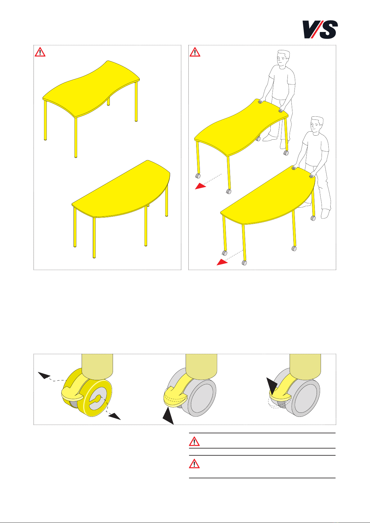
Shift+ Base Freiformtische.
Normen:
Geprüft nach DIN EN 1729 Teil 1 und 2, Größenklasse 2 bis 7,
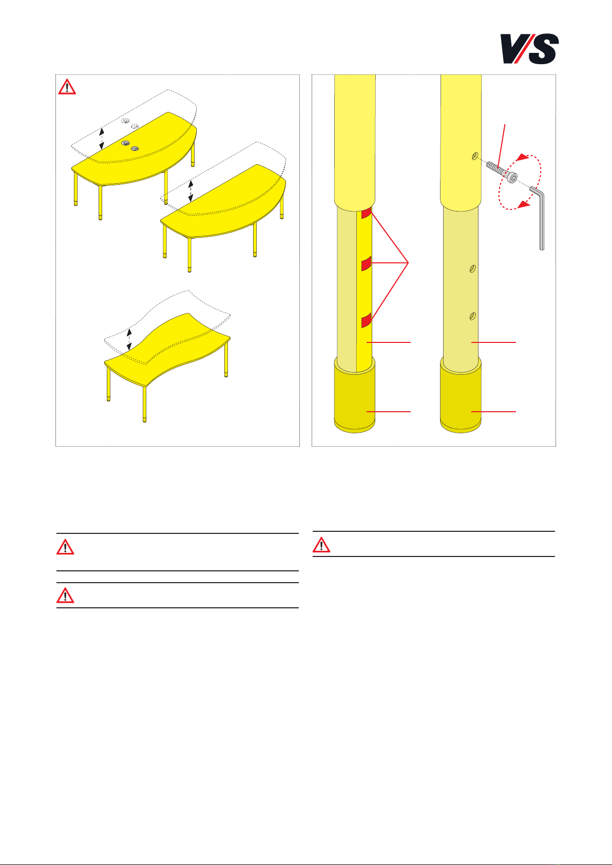
bzw. Grössenklasse 3-7 (bei Höhenverstellung).
Lieferumfang:
Das Produkt wird fertig montiert ausgeliefert.
Montage und Inbetriebnahme:
Vor Verwendung den Rollenschutz entfernen.
Betrieb:
Beachten Sie die Hinweise auf den folgenden Seiten.
Fehlersuche und Service:
Bei eventuell auftretenden Fehlern, wenden Sie sich bitte an
Wartung und Reinigung:
Im Internet: vs.de/kataloge/reinigung/
Weitergabe und Entsorgung:
Bei Weitergabe des Produkts ist auch diese Bedienanleitung zu
übergeben. Die gekennzeichneten E-Komponenten dürfen nicht
über den Hausmüll entsorgt werden. Sie müssen
von dem Möbel getrennt werden, bevor das Möbel der
Entsorgung zugeführt wird. Die Entsorgung erfolgt
an zugelassenen Sammel- und Rücknahmestellen.
Bestimmung:
Freiformtische mit Gleitern oder Rollen und mit oder ohne
Höhenverstellung für Schulen, Hochschulen, Seminare und
Weiterbildung. Für eine nicht bestimmungsgemäße Benut-
zung wird keine Haftung übernommen. Gültig für die Mo-
delle 01442, 01443, 01445 bei Verwendung in geschlossenen
Räumen. Maximale Belastung: 150 kg.
Allgemeiner Hinweis zum Lesen und
Aufbewahren der Anleitung:
Lesen Sie diese Anleitung und vor allem die Sicherheitshinweise
vor Benutzung der Produkte genau durch und beachten Sie die-
se. Bewahren Sie die Anleitung zum späteren Nachlesen sorg-
fältig auf und geben Sie diese an andere Benutzer weiter.
Allgemeiner Sicherheitshinweis:
In unseren Bedienanleitungen verwenden wir folgende Symbole
und Hinweise:
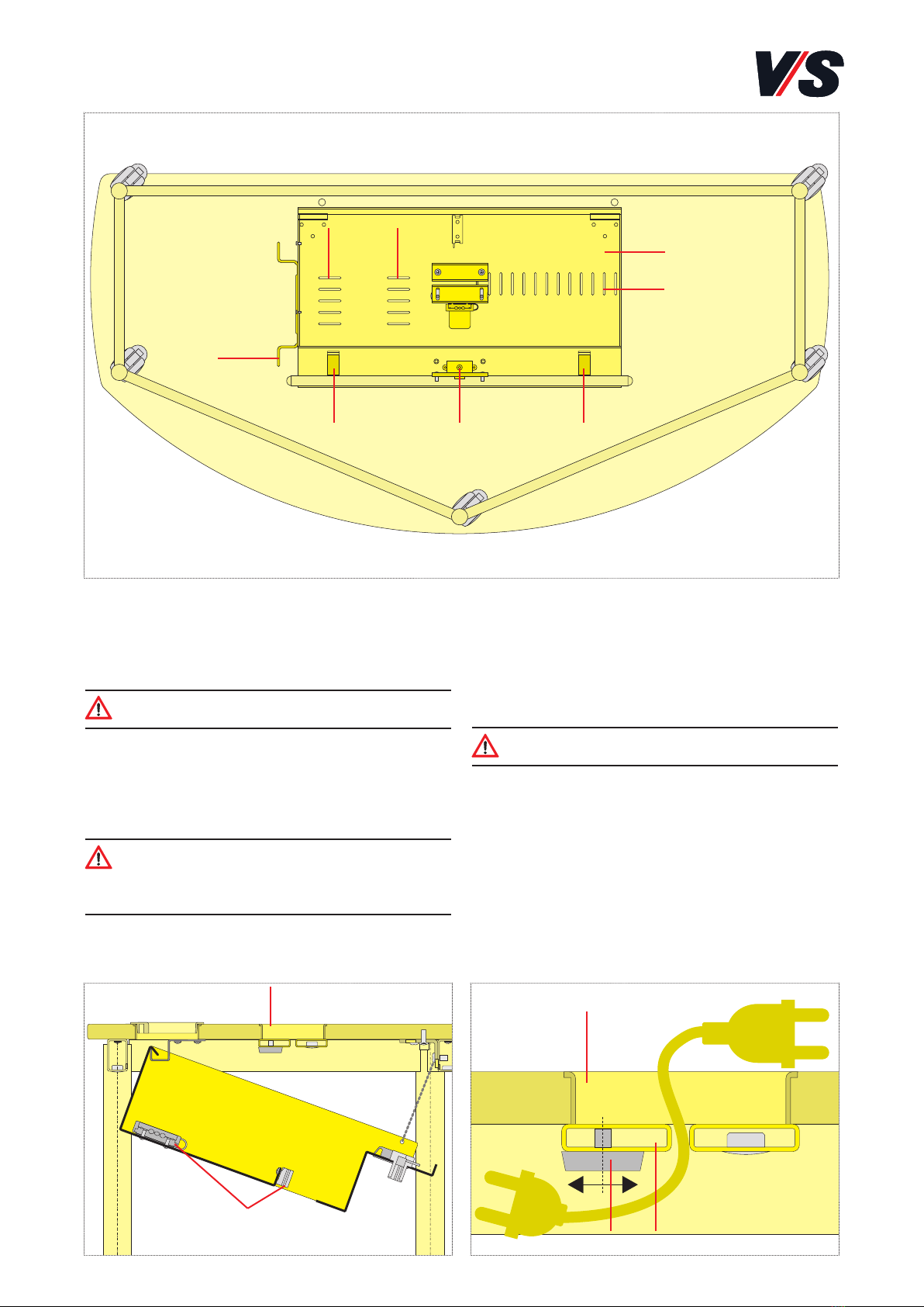
Wichtig: Bei diesem Symbol handelt es sich um einen
wichtigen Montagehinweis.
Achtung! Bei diesem Symbol handelt es sich um einen
sehr wichtigen Hinweis.
Im Internet:
Sie finden diese Anleitung im Internet (siehe Kopfleiste).

2
Achtung! Rollen sind Verschleißteile - bitte in
regelmäßigen Abständen prüfen und austauschen.
Achtung! Rollen sind nach jedem Ortswechel fest-
zustellen - nur dann ist der Tisch funktionsfähig.
feststellenlösenRollenschutz entfernen
1. Mobilität
1.1 Gleiter:
Freiformtische Shift+ können mit Gleitern ausgestattet
werden
(1) (2) (3)
Achtung!
Achtung!
1.2 Rollen:
Sind Freiformtische Shift+ mit Rollen ausgestattet, ist vor
dem Bewegen die Arretierung zu lösen. Nach erfolgtem
Ortswechsel sind alle Rollen wieder fest zu stellen. Es dürfen
nur unbelastete Tische gerollt werden - die Tischfläche muss
frei sein.
(1) Vor Verwendung ist der Rollenschutz zu entfernen.
(2) Durch Druck nach oben die Feststellung lösen, um den
Tisch rollen zu können. (3) Durch Druck nach unten ist die
Rolle nach Ortswechsel wieder festzustellen.

3
(1)
(4)
(3)
(4)
(3)
(2)
2. Höhenverstellung
Höhenverstellbare Freiformtische Shift+ gibt es mit Gleitern
und Rollen. Es können die Höhen der Größen 3 bis 7 einge-
stellt werden. Die Größenmarkierung (1) befindet sich auf
der Außenseite eines der Tischbeine.
Achtung! Es dürfen nur unbelastete Tische in der Höhe
verstellt werden - die Tischfläche muss frei sein.
Achtung! Bei Tischen mit Rollen müssen die Rollen
festgestellt werden.
Die Einstellung der Tischhöhe erfolgt mit den Inbus-
schrauben (2) auf der Innenseite der Tischbeine.
Schraube (2) mit Inbusschlüssel (SW 5) lösen und heraus-
drehen. Den unteren Teil (3) des Beines mit dem Innenrohr
(4) in die gewünschte Position bringen, die Inbusschraube
einstecken und wieder festdrehen.
Bei allen anderen Tischbeinen genauso verfahren.
Achtung! Alle Beine eines Tisches müssen auf die
gleiche Höhe eingestellt werden.
Achtung!

4
(3)
(4)
(1)
(5)
(6)
(7)
(8)
(9)
(2)
Achtung!
3. Befestigung Monitorarm
an Modell 01443:
Der Führungszapfen (1) wird auf den hinteren Kabeldurch-
lass (2) gestellt und mit der mitgelieferten Schraube (3)
befestigt; die Schraube muss durch die entsprechende
Öffnung des Versteifungswinkels (4) geführt werden.
Anschliessend den Zierring (5) und die Verdrehsicherung (6)
auf den Führungszapfen stecken.
Wichtig! Den Zierring in der Farbe des Monitorarmes
(silber oder weiss) auswählen.
Achtung! Die große Abkantung der Verdrehsicherung (6)
muss in den Kabeldurchlass eintauchen.
Dann Druckring (7) oben auf den Führungszapfen stecken
und die Lagerbuchse (8) komplett darüber stülpen. Danach
wird der Monitorarm (9) aufgesteckt. Die Anschlusskabel
des Monitors sind am Monitorarm zu befestigen und durch
den Kabeldurchlass in die Kabelwanne zu führen.
Achtung!
Kabel nicht quetschen.
Achtung! Ausreichende Kabellänge für jede
Monitorposition berücksichtigen.
Für die Montage und Demontage des Monitors am Monitor-
arm, sowie für das Einstellen des Monitorarms beachten Sie
bitte die mitgelieferte Anleitung des Herstellers.

5
4. Kabelwanne öffnen:
Zum Öffnen der abklappbaren Kabelwanne (1) ist zuerst das
Schloss (2) mit dem mitgelieferten Schlüssel zu öffnen. An-
schließend sind die zwei Sicherungsriegel (3) zu betätigen.
Achtung! Die Kabelwanne vorsichtig nach unten
abklappen, bis diese durch die Aushängsicherung (4) in
Position gehalten wird.
5. Stromversorgung:
Beigelegte Steckdosenleiste mit Kabelbindern (nicht im Liefer-
umfang) in den vorgesehenen Langlöchern (5) sichern.
Achtung! Stromkabel sind generell mit einer Zugent-
lastung (7) zu sichern oder bei Entnahme zu Entsichern.
Kabelüberlängen sind am Bügel (6) aufzuwickeln.
6. Kabel-Durchlass:
Durch den vorderen Kabelauslass (8) der Tischplatte geführte
Kabel sind durch das Verstellen der Durchlassöffnung zu
sichern. Dazu Stellschrauben (9) lösen und durch Verschieben
der Kabelklemme (10) die Größe der Öffnung dem Kabel-
querschnitt anpassen, anschließend Stellschrauben wieder
feststellen.
Achtung!
Kabel nicht quetschen.
7. Kabelwanne schließen:
Kabelwanne nach oben drücken bis Sicherungsriegel hörbar
einrasten und abschließen.
(1)
(2) (3)
(3)
(5)
(6)
(5)(5)
(9)
(8)
(8)
(4)
(7) (10)

6
VS Vereinigte Spezialmöbelfabriken GmbH & Co.KG
http://links.vs-service.com/downloads/70-215_V03_DEEN_ShiftBase-Gruppen-145948.pdf
01443
01442
01445
01445
OPERATING INSTRUCTIONS 70-215 V03 000918
Shift+ Base free-form tables.
Standards:
Inspected in accordance with DIN EN 1729 Parts 1 and 2,
size class 2 to 7 or size class 3 to 7 (with height adjustment).
Scope of delivery:
The product is supplied fully assembled.
Assembly and initial use:
Remove the castor protection before using.
Use:
Please take account of the notes on the following pages.
Faults and service:
If any faults occur, please contact our Customer Service:
Maintenance and cleaning:
On the Internet: vs.de/kataloge/reinigung/en
Product transfer and Disposal:
If the product is transferred to a new owner or user then it
must be accompanied by these Instructions. The indicated
electric and electronic components must not be
disposed of with the ordinary waste. They must be
removed from the furniture unit before the unit is
sent for disposal. They are to be disposed of at
authorized collection and return points.
Intended use:
Free-form tables with glide elements or castors and with or
without height adjustment for schools, colleges, seminars
and further education establishments. No liability will be
assumed for any use other than that intended. Valid for
models 01442, 01443, 01445 for use in closed premises.
Maximum load: 150 kg.
General note on reading and retaining
these Instructions:
Read these Instructions and, in particular, the safety instruc-
tions carefully before using the products and adhere to
these. Keep these Instructions in a safe place for future
consultation and communicate them to other users.
General note on safety:
The following symbols and notes are used in our Instructions
for Use:
Important: This symbol indicates an important
assembly note.
Caution!
This symbol indicates a very important note.
On the Web:
You can find these Instructions on the Web:

7
Caution! The castors are subject to wear – please
check and replace at regular intervals.
Caution! The castors must be locked every time the
table is moved to a new location - only then is the
table suitable for use.
LockReleaseRemove castor protection
1. Mobility
1.1 Glide elements:
Shift+ free-form tables can be equipped with glide elements.
(1) (2) (3)
Caution!
Caution!
1.2 Castors:
In the case of Shift+ free-form tables with castors it is nec-
essary to release the locking mechanism before moving the
tables. When the table has been moved to the desired posi-
tion, all the castors must be locked again. There must be no
load on the table when it is moved – the table top must be
free from objects.
(1) Remove the castor protection before use.
(2) Then press the locking mechanism upwards to release it
in order to wheel the tables. (3) Press the mechanism down
again to lock the castors after moving the table to a new
location.

8
(1)
(4)
(3)
(4)
(3)
(2)
2. Height adjustment
Height-adjustable Shift+ free-form tables are available with
glide elements and castors. The height can be set size 3 to
7. The size markings (1) are located on the outside of one of
the table legs.
Caution! There must be no load on the table when the
height is adjusted – the table top must be free from
objects.
Caution! If the table is equipped with castors, these
must be locked.
The table height is adjusted using the Allen (2) on the in-
side of the table legs. Unscrew the screw (2) using an Allen
key (size 5) and remove it. Adjust the inside tube (4) at the
lower leg section (3) to the required position, insert the
Allen screw and tighten it again.
Caution! All the legs of a table must be adjusted to
the same height.
Caution!

9
(3)
(4)
(1)
(5)
(6)
(7)
(8)
(9)
(2)
Caution!
3. Fixing the monitor arm
on model 01443:
Place guide pin (1) on the rear cable passage (2) and fix it
in place using the screw supplied (3); the screw must be
passed through the corresponding opening in the reinforc-
ing bracket (4). Next place the cover ring (5) and the anti-
twist protector (6) on the guide pin.
Important! Choose the cover ring to be the same
colour as the monitor arm (silver or white).
Caution! The large bended edge of the anti-twist pro-
tector (6) must be inserted in the cable passage.
Then place the pressure ring (7) on top over the guide pin
and push the bushing (8) fully over it. Then insert the moni-
tor arm (9). The monitor connecting cables must be fas-
tened to the monitor arm and guided through the cable
passage into the cable tray.
Caution!
Do not squeeze or crush the cable.
Caution! Make sure that the cable is long enough to
reach all monitor positions.
Please refer to the supplied manufacturer's instructions
when mounting or dismounting the monitor at the monitor
arm and when adjusting the monitor arm itself.

10
4. Opening the cable tray:
To open the folding cable tray (1), first unlock the lock (2)
using the key provided. Then unlock the two locking barsl
(3).
Caution! Carefully fold the cable tray downwards until
it is held in position by the retainer (4).
5. Power supply:
Secure the supplied socket strip in the elongated (5) pro-
vided for this purpose using cable ties (not included in the
scope of delivery).
Caution! Power cables should generally be secured us-
ing a strain relief mechanism (7) and be released on
removal. Excess cable lengths should be wound around
the clip (6).
6. Cable passage:
Cables that pass through the front cable (8) in the table top
must be secured by adjusting the opening of the passage. To
do this, release the adjusting screws (9) and push and adjust
the cable clamp (10) until the size of the opening matches
the cable cross-section. Then tighten the screws again.
Caution!
Do not squeeze or crush the cable.
7. Closing the cable tray:
Push the cable tray up until the locking bars audibly engage
and then lock it again.
(1)
(2) (3)
(3)
(5)
(6)
(5)(5)
(9)
(8)
(8)
(4)
(7) (10)
This manual suits for next models
3
Table of contents
Languages:
Other VS Indoor Furnishing manuals