VS 21707 Manual

VS Vereinigte Spezialmöbelfabriken GmbH & Co.KG
http://links.vs-service.com/downloads/70-227_V02_DEEN_RoundTable-200-220-145950.pdf
21707
21708
BEDIENUNGS-/MONTAGEANLEITUNG: 70-227 V02 000918
RoundTable ø 200, 220 cm.
Bestimmung:
Die vorliegenden Tischmodelle sind als Objekt- bzw. Bespre-
chungstische konzipiert und ausschließlich für diese Nutzung
vorgesehen. Für eine nicht bestimmungsgemäße Benutzung
wird keine Haftung übernommen. Gültig für die Modelle
21707, 21708 bei Verwendung in geschlossenen Räumen.
Allgemeiner Hinweis zum Lesen und
Aufbewahren der Anleitung:
Lesen Sie diese Anleitung und vor allem die Sicherheitshin-
weise vor Benutzung der Produkte genau durch und beachten
Sie diese. Bewahren Sie die Anleitung zum späteren Nachlesen
sorgfältig auf und geben Sie diese an andere Benutzer weiter.
Allgemeiner Sicherheitshinweis:
In unseren Montageanleitungen verwenden wir folgende
Symbole und Hinweise:
Wichtig! Bei diesem Symbol handelt es sich um einen
wichtigen Montagehinweis.
Achtung! Bei diesem Symbol handelt es sich um einen
sehr wichtigen Hinweis.
Im Internet:
Diese Anleitung wird Ihnen auch online als Download
bereitgestellt über den in der Kopfleiste angegebenen Link.
Normen:
Geprüft nach DIN EN 15372 Prüfstufe 2 (mittlere Nutzung).
Lieferumfang:
Die Produkte werden zerlegt ausgeliefert.
Fehlersuche und Service:
Bei eventuell auftretenden Fehlern, wenden Sie sich bitte an
Wartung und Reinigung:
Im Internet: vs.de/kataloge/reinigung/
Weitergabe und Entsorgung:
Bei Weitergabe des Produkts ist auch diese Anleitung zu
übergeben.
Die gekennzeichneten E-Komponenten dürfen nicht über
den Hausmüll entsorgt werden.
Sie müssen von dem Möbel getrennt werden, bevor
das Möbel der Entsorgung zugeführt wird.
Die Entsorgung erfolgt an zugelassenen Sammel-
und Rücknahmestellen.

2
(1)
(1)
(3) (3)
(6)
(6)
(2)
(4)
(5)
(1)
Innenkreuz und Kufen verbinden
Für ausreichend Platz bei der Montage sorgen! Tischfläche
und Boden sind vor Kratzern zu schützen. Benutzen Sie als
Unterlage ein weiches, nicht rutschendes Material (Teppich
oder Decke). Legen Sie das massive Stahl-Innenkreuz (2) mit
den Bohrungen nach oben auf den Boden. Bringen Sie es in
die korrekte Montageposition.
Anschließend werden alle 4 Blendkufen (1) auf das Innen-
kreuz aufgeschoben, bis die Bohrungen für die Stabilisie-
rungsplatte (4) deckungsgleich sind. Dann wird diese Platte
mit insgesamt 8 mitgelieferten Senkkopfschrauben (5)
M 10x25 mm durch die Kufen mit dem Innenkreuz fest ver-
schraubt.
Achtung! Für die Montage werden min. 2 Personen
benötigt, um den Tisch sicher zu bewegen.
Abschließend sind die Gewindestifte (3), die jeweils von
unten die Tischkufen durch Spreizwirkung stabilisieren, fest
anzuziehen.
Montage der Gleiter
Mitgelieferte Stellgleiter (6) werden anschließend gleichmä-
ßig auf eine mittlere Position in die Gewindebohrung einge-
dreht.
Eine Höhenausrichtung des Tisches ist in einem Bereich von
15 mm möglich.
Achtung! Beim Justieren der Höhenausgleichsschraube
auf Unversehrtheit des Fußbodens achten.
Achtung!

3
(7)
(8)
(4)
(6)
(9)
(7)
Fußkreuz mit Säule verbinden
Die Montage der Innensäule (7) erfolgt mit den mitgeliefer-
ten 8 Schrauben (8) M 8x20 mm, die von oben auf die Stabi-
lisierungsplatte (4) geschraubt werden.
Säule mit Tragrahmen verbinden
Die Montage des Tragrahmens (9) erfolgt mit den mitgelie-
ferten 8 Schrauben (8) M 8x20 mm, die von unten mit der
Innensäule (7) verschraubt werden.
Achtung!
Kippgefahr! Mit 2 Personen arbeiten.
Achtung!

4
(4)
(5)
(4)
(6)
(3)
(1)
(2)
Säulenverblendung montieren
Eine Hälfte der Säulenverblendung (1) wird fest mit der In-
nensäule (2) durch die mitgelieferten 6 Blechschrauben (3)
verbunden.
Die andere Hälfte der Säulenverblendung wird erst nach der
abgeschlossenen Verkabelung fixiert.
Tischplatten verbinden
Zuerst die beiden Hälften der Tischplatte mit der Oberfläche
nach unten auflegen. Um Kratzer bzw. Beschädigungen der
Oberfläche zu vermeiden ist zum Schutz der Oberfläche ein
nicht rutschendes Material (Decke, Montagematte) unterzu-
legen.
Anschließend sind die Tischhälften in eine korrekte Monta-
geposition zu bringen und mit den mitgelieferten 6 Tischver-
bindern (4) fest zu verschrauben.
Tragerahmen und Tischplatte verbinden
Anschließend ist die montierte Tischplatte (5) umzudrehen
und in die korrekte Montageposition auf dem Tragrahmen zu
bringen, damit sie von unten mit den mitgelieferten Holz-
schrauben fest mit der Tragrahmenkonstruktion (6) ver-
schraubt werden kann.
Montage Klappen
Die Klappen für die Elektrifizierungssets sind vormontiert.
Achtung!

5
(7)
(6)
(7)
(8)
(8)
(9)
Befestigung der Kabelwannenhälften
Die beiden Kabelwannenhälften (7) werden von unten mon-
tiert. Zuerst die mitgelieferten 8 Rändelschrauben (8) von
unten in die vorgesehenen Gewindeöffungen im Tragerahmen
leicht eindrehen.
Anschließend die Kabelwannenhälften von unten einklinken,
in Position schieben und fest mit dem Tragrahmen (6) ver-
schrauben.
Höhenjustierung des Tisches
Tisch leicht anheben und die Höhenausgleichsschrauben (9)
auf die gewünschte Höhe, bis der Tische in der Waage steht,
ausrichten.
Die Höhenausrichtung des Tisches ist in einem Bereich von
15 mm möglich.
Achtung! Beim Justieren der Höhenausgleichsschraube
auf Unversehrtheit des Fußbodens achten.

6
(5)
(6)
(4)
(4)
(3)
(5)
(7)
(2)
(3)
(1)
Elektrifizierung
Kabelwanne (4), Haltebleche (5) und Steckdosenleisten (6)
sind werkseitig vormontiert. Montage wird nur dann erforder-
lich, wenn die Steckdosenleisten später nachgerüstet werden.
Die Zugentlastung ist immer vorzunehmen.
Zugentlastung
Abgehende Kabel sind immer mit einer Zugentlastung (3) zu
sichern. Die beiden Zugentlastungen (3) befinden sich im un-
teren Drittel des Stützfuß/Kabelschachtes. Mit Schraube (3)
sichern.
Achtung! Kabel nicht quetschen.
Achtung! Ausreichende Kabellänge für jede Position
berücksichtigen.
Blende fixieren
Die Säulenverblendung (1) wird mit den vorgesehenen
Schlitzen in die eingedrehten mittleren Schrauben einge-
hängt. Die eingedrehten Schrauben müssen ein Spiel von
ca. 3 mm aufweisen
Nachrüstung Elektrifizierungssatz
Zunächst die 8 mitgelieferten Rändelschrauben (7) von un-
ten in die vorgesehenen Bohrungen leicht eindrehen. Dann
die Wannenhälften (4) von unten einklinken, in Position
schieben und fest mit dem Tragrahmen verschrauben.
Anschließend die Steckdosenleisten mit den vormontierten
Halteblechen (5) von oben in die korrekte Montageposition
bringen. Dann mit den 4 mitgelieferten Torx-Schrauben
M5x12 von unten festschrauben.
Wichtig!
Eine Zugentlastung ist immer durchzuführen.

7
VS Vereinigte Spezialmöbelfabriken GmbH & Co.KG
http://links.vs-service.com/downloads/70-227_V02_DEEN_RoundTable-200-220-145950.pdf
21707
21708
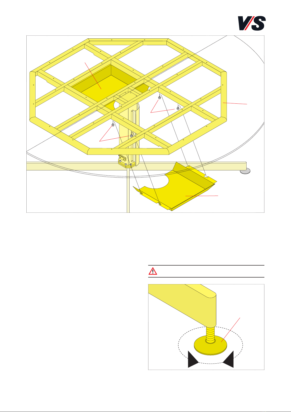
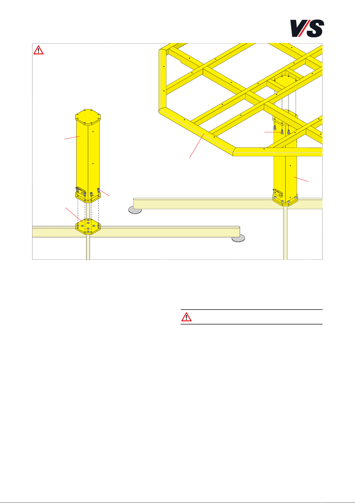
OPERATING/ASSEMBLY INSTRUCTIONS: 70-227 V02 000818
RoundTable ø 200, 220 cm.
Intended use:
These table models have been designed as office and/or con-
ference tables and are intended exclusively for such use. No
liability will be assumed for any use other than that intend-
ed. Valid for models 21707, 21708 for use in closed premises.
General note on reading and
retaining these Instructions:
Read these Instructions and, in particular, the safety instruc-
tions carefully before using the products and adhere to
these. Keep these Instructions in a safe place for future con-
sultation and communicate them to other users.
General note on safety:
The following symbols and notes are used in our Assembly
Instructions:
Important! This symbol indicates an important
assembly note.
Caution!
This symbol indicates a very important note.
On the Web:
These Instruc,tions are also available online for download via
the link indicated at the top of the page.
Standards:
Inspected in accordance with DIN EN 15372,
level 2 (moderate use).
Scope of delivery:
The products are supplied disassembled.
Faults and service:
If any faults occur, please contact our Customer Service:
Maintenance and cleaning:
On the Internet: vs.de/kataloge/reinigung/en
Product transfer and Disposal:
If the product is transferred to a new owner or user then it
must be accompanied by these Instructions.
The indicated electric and electronic components must not
be disposed of with the ordinary waste.
They must be removed from the furniture unit
before the unit is sent for disposal.
They are to be disposed of at authorized collection
and return points.

8
(1)
(1)
(3) (3)
(6)
(6)
(2)
(4)
(5)
(1)
Connecting the inner cross and skids
Ensure that you have sufficient space to perform assembly!
The table top and floor must be protected against scratches.
To do this, place a soft, non-slip material (carpet or blanket)
underneath. Place the solid steel inner cross (2) on the floor
with the drill holes facing upwards. Move it to the correct
position for assembly.
Next slide all 4 cover-type skids (1) onto the inner cross until
the drill holes for the stabilizing plate (4) are aligned with
the holes on the cross. Then use a total of 8 M 10x25 mm
countersunk-head screws (5) to screw this plate firmly
through the skids and onto the inner cross.
Caution! A minimum of two people are needed for as-
sembly in order to move the table safely.
Then tighten the threaded pins (3), that stabilize each of the
table skids from below by means of a spreading eect.
Mounting the glide elements
Next screw (6) in the supplied adjustable glide elements
evenly until they are half-way into the threaded hole.
The height of the table can be adjusted within a range of
15 mm.
Caution! When adjusting the screw-type height
adjuster, make sure that the floor is not damaged.
Caution!

9
(7)
(8)
(4)
(6)
(9)
(7)
Connecting the base cross to the pillar
The inner pillar (7) is mounted using the 8 M 8x20 mm
screws supplied (8) These must be screwed from above into
the stabilizing plate (4).
Connecting the pillar to the supporting
frame
The supporting frame (9) is mounted using the 8 M 8x20
mm screws supplied (8). These must be screwed from below
into the inner pillar (7).
Caution! Danger of tipping! The work must be per-
formed by two people.
Caution!

10
(4)
(5)
(4)
(6)
(3)
(1)
(2)
Fixing the pillar cover
One half of the pillar cover (1) is firmly fixed to the inner pil-
lar (2) using the 6 self-tapping screws supplied (3).
The other half of the pillar cover is not fixed until cabling has
been completed.
Connecting the table tops
First of all, lay down the two halves of the table top with
the upper surface facing down. To prevent the surface
against scratches or damage, make sure that they are lying
on non-slip material (blanket, assembly mat).
Then bring the two halves of the table together in the cor-
rect assembly position and screw them together firmly using
the 6 table connectors supplied (4).
Connecting the supporting frame and
table top
Now turn over the assembled table top (5) and place it in
the correct position for assembly on the supporting frame so
that it can be screwed firmly to the structure of the sup-
porting frame (6) from below using the supplied wood
screws.
Mounting the flaps
The flaps for the sets of electrical connections are pre-
mounted.
Caution!

11
(7)
(6)
(7)
(8)
(8)
(9)
Fixing the halves of the cable tray
The two halves of the cable tray (7) are assembled from be-
low. First of all, screw the 8 knurled screws supplied (8) a lit-
tle way into the threaded holes provided in the supporting
frame from below.
Then latch on the halves of the cable trays from below, slide
them into position and screw them firmly to the supporting
frame (6).
Adjusting the table height
Lift the table slightly and align the screw-type height ad-
justers (9) to the required height at which the table is level.
The height of the table can be adjusted within a range of
15 mm.
Caution! When adjusting the screw-type height ad-
juster, make sure that the floor is not damaged.

12
(5)
(6)
(4)
(4)
(3)
(5)
(7)
(2)
(3)
(1)
Electrical connections
The cable (4), retaining plates (5) and socket strips (6) are
preassembled ex works. Assembly is only necessary if the
socket strips are retrofitted later. The strain relief mechanism
must always be used.
Strain relief
Cables exiting the unit must always be secured using a strain
relief mechanism (3). The two strain relief mechanisms (3)
are located in the lower third of the supporting leg/cable
duct. Secure using the screw (3).
Caution! Do not squeeze or crush the cable.
Caution! Make sure that the cable is long enough to
reach all positions.
Fixing the cover
Fix the pillar cover (1) by sliding the slots provided for this
purpose over the centrally inserted screws. The inserted
screws must have a play of approx. 3 mm.
Retrofitting the electrical connector kit
First of all, screw the 8 knurled screws supplied (7) a little
way into the holes provided from below. Then latch on the
halves of the cable tray (4) from below, slide them into po-
sition and screw them firmly to the supporting frame.
Next, place the socket strips together with the pre-assem-
bled retaining plates (5) in the correct position from above.
Then use the 4 M5x12 Torx screws supplied to screw them
in place from below.
Important!
The strain relief mechanism must always be used
This manual suits for next models
1
Table of contents
Languages:
Other VS Indoor Furnishing manuals

VS
VS Niche 800 Series User manual

VS
VS 31506 User manual

VS
VS LIGNOdur Uno-M-Step 22405 User manual

VS
VS Pareto-Twin 21758 User manual

VS
VS Shift+ Base Series User manual

VS
VS JustBe 40630 User manual

VS
VS 910 Series User manual

VS
VS 09448 User manual

VS
VS NF-Move Export 32500 User manual

VS
VS 600 Series User manual
Popular Indoor Furnishing manuals by other brands

Dorel
Dorel Ameriwood INDUSTRIES 5598026PCOM manual

ATD Tools
ATD Tools ATD-81055 owner's manual

Next
Next BRONX 966749 Assembly instructions

Nightingale
Nightingale SHERMAN HD 9000 Series User handbook

Mosaic
Mosaic Picket Rocker FSMVPT2089 Assembly instructions & user manual

Safavieh
Safavieh AMH1517A manual