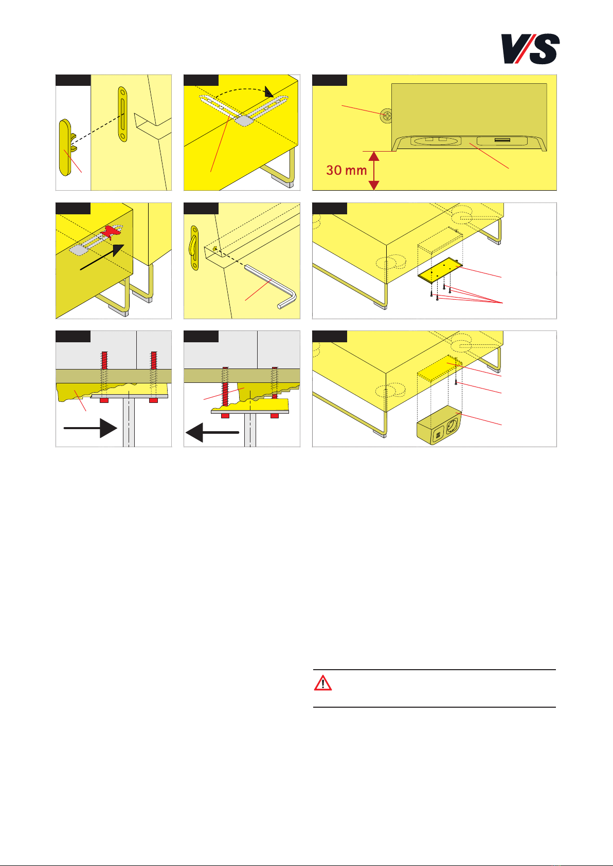
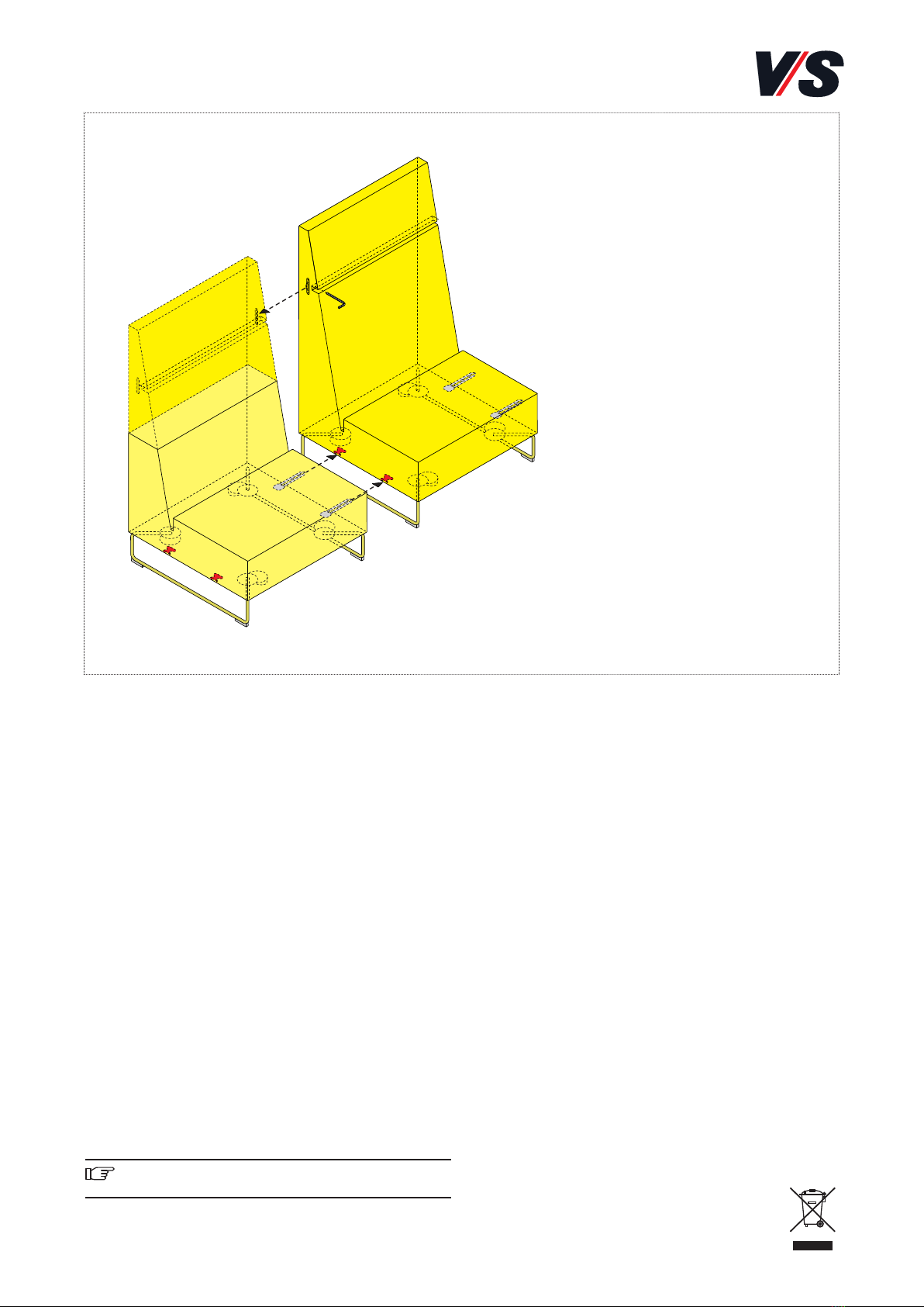
VS Lounge HiBack Series User manual

1
VS Vereinigte Spezialmöbelfabriken GmbH & Co.KG
http://links.vs-service.com/downloads/71-1006_V04_DEENFR_Lounge-HiBack-115903.pdf
Normen:
Geprüft nach DIN EN 16139.
Lieferumfang:
Das Produkt wird fertig montiert ausgeliefert.
Betrieb:
Beachten Sie die Hinweise auf der folgenden Seite.
Fehlersuche und Service:
Bei eventuell auftretenden Fehlern, wenden Sie sich bitte an
Wartung und Reinigung
Im Internet: vs.de/kataloge/reinigung/
Weitergabe und Entsorgung:
Bei Weitergabe des Produkts ist auch diese Anleitung zu
übergeben. Für eine umweltfreundliche Entsorgung infor-
mieren Sie sich bitte bei Ihrer zuständigen Kommune.
Die gekennzeichneten E-Komponenten dürfen nicht über
den Hausmüll entsorgt werden.
Sie müssen von dem Möbel getrennt werden, bevor
das Möbel der Entsorgung zugeführt wird.
Die Entsorgung erfolgt an zugelassenen Sammel-
und Rücknahmestellen.
BEDIENUNGSANLEITUNG: 71-1006 V04 000721
Serie Lounge, Serie Lounge HiBack.
30110-30113, 30120-30133.
Bestimmung:
Das vorliegende Sitzmöbel wurde ausschließlich für den
Objektbereich konzipiert und ist somit auch nur für diesen
Verwendungszweck bestimmt. Eine andere oder darüber
hinausgehende Benutzung (z. B. in Werkstätten, Lagerbereich
oder Feuchträumen) gilt als nicht bestimmungsgemäß. Für
hieraus entstehende Schäden haftet die Firma VS Vereinigte
Spezialmöbelfabriken GmbH&Co.KG nicht.
Allgemeiner Hinweis zum Lesen und
Aufbewahren der Anleitung:
Lesen Sie diese Anleitung und vor allem die Sicherheits-
hinweise vor Benutzung der Produkte genau durch und
beachten Sie diese. Bewahren Sie die Anleitung zum späteren
Nachlesen sorgfältig auf und geben Sie diese an andere
Benutzer weiter.
Allgemeiner Sicherheitshinweis:
In unseren Bedienanleitungen verwenden wir folgende
Symbole und Hinweise:
Wichtig! Bei diesem Symbol handelt es sich um einen
wichtigen Montagehinweis.
Im Internet:
Sie finden diese Anleitung im Internet (siehe Kopfleiste).

2
(1) (2)
(3)
(4)
(4) (7)
(5)
(6)
(7)
(8)
1 7
8
9
2
3 4
5 6
(5)
(8)
Vorgehensweise bei Verkettung
1. Abdeckkappen (1) entfernen ausklappen [Bild 1].
2. Verbinder (2) ausklappen und Elemente zusammenschieben.
Verbinder muss in das Gegenstück einrasten [Bild 2+3].
3. Mit dem Innensechskantschlüssel SW 7 (3) aus dem Bei-
pack die Elemente durch die Öffnung im Polster
miteinander verriegeln (links drehen!) [Bild 4].
4. Die Demontage erfolgt in umgekehrter Reihenfolge.
5. Bei Bodenunebenheiten die Schrauben mit Innensechs-
kantschlüssel SW 5 lösen. Die Ausgleichskeile (4) einstellen
(gegeneinander versetzen) und die Schrauben wieder fest-
drehen. (Bei der maximalen Verstellung muss die Schraube
komplett herausgedreht werden) [Bild 5+6].
Vorgehensweise bei Elektrifizierung
1. Positionieren Sie die Montageplatte (5) mit einem Abstand
von 30 mm zur Vorderkante des Lounge-Elementes. Die
Montage erfolgt i.d.R. mittig von einem geraden Lounge-
Element. Alternativ erfolgt die Anbringung nach Kunden-
wunsch [Bild 7].
2. Befestigen Sie die Montageplatte (5) der Elektrifizierungs-
einheit (8) an der Unterseite des Lounge-Elementes mit vier
Spanplattenschrauben PH 4,0x20 mm (6) [Bild 8].
3. Rasten Sie nun die Elektrifizierungseinheit (8) an der
Montageplatte (5) ein (Schubrichtung nach rechts) [Bild 9].
Die Zugentlastung für das Anschlusskabel ist bereits in
der Einheit integriert.
Achtung! Die Netzanschlussleitung zur Elektrifizie-
rungseinheit muss so positioniert werden, dass Stolper-
und Sturzgefahren vermieden werden.
4. Zuletzt müssen Sie die Einheit gegen Demontage sichern
indem Sie links neben die Einheit eine Sicherungsschraube (7)
(Spanplattenschrauben (6) PH 4,0x20 mm) setzten. Diese soll
verhindern, dass die Elektrifizierungseinheit (8) versehentlich
aus der Montageplatte (5) geschoben werden kann [Bild 9].

3
VS Vereinigte Spezialmöbelfabriken GmbH & Co.KG
http://links.vs-service.com/downloads/71-1006_V04_DEENFR_Lounge-HiBack-115903.pdf
ASSEMBLY INSTRUCTIONS: 71-1006 V04 000721
Serie Lounge, Serie Lounge HiBack.
30110-30113, 30120-30133.
Intended use:
This seating element has been designed exclusively for use in
commercial environments and is therefore intended solely for
this purpose. Any other use that goes beyond the intended
purpose (e.g. in workshops, storage areas or damp locations)
is classed as not in accordance with the intended use. The
company VS Vereinigte Spezialmöbelfabriken GmbH&Co.KG
shall not be held liable for damage arising from such non-
intended use.
General note on reading and storing the
instructions:
Please read these instructions and in particular the notes on
safety carefully and in full before using the products. Keep
the instructions in a safe place for subsequent reference and
pass them on to other users.
General note on safety:
We use the following symbols and notes in our
assembly instructions:
Important! This symbol refers to
an important note on assembly.
On the internet:
Alternatively, they can be downloaded: (see header title).
Standardize:
Tested according to DIN EN 16139.
Scope of delivery:
The product is delivered fully assembled.
Operation:
Follow the instructions on the following page.
Troubleshooting and service:
If faults occur, please contact our
Maintenance and Cleaning
On the internet: vs.de/kataloge/reinigung/en
Forwarding and Disposal:
If the product is passed on to any third party then these instruc-
tions
must be supplied with it. Please contact your relevant
local authority for information on environmentally compatible
disposal. The indicated electric and electronic components
must not be disposed of with the ordinary waste.
They must be removed from the furniture unit before
the unit is sent for disposal. They are to be disposed
of at authorized collection and return points.

4
Procedure for concatenation
1. Remove protective caps (1) and fold out the connector
[Fig. 1].
2. Fold out the connecting pieces (2) and push the elements
together. The connecting pieces must engage in the corre-
sponding retainers [Fig. 2+3].
3. Using the supplied Allen key WAF 7 (3), lock the elements
to each other through the opening in the upholstery (turn
counterclockwise!) [Fig. 4].
4. Disassembly is performed in reverse sequence.
5. In the event of floor unevenness release the screws with an
Allen key WAF 5. Adjust the levelling wedgesile (4) (offset)
and screw again. (At maximum adjustment the screws must
be twisted out completely) [Fig. 5+6].
Procedure for establishing electrical
connections
1. Position the mounting plate (5) at a distance of 30 mm
from the front edge of the Lounge element. Assembly is
usually performed in the centre of a straight Lounge element.
Alternatively, installation is possible in accordance with the
customer’s requirements [Fig. 7].
2. Fix the mounting plate (5) of the electrical connection
unit (8) to the underside of the Lounge element using four
PH 4.0x20 mm chipboard screws (6) [Fig. 8].
3. Now engage the electrical connection unit (8) at the
mounting plate (5) (push to the right) [Fig. 9]. The strain
relief mechanism for the connecting cable is already inte-
grated in the unit.
Caution! The mains power line to the electrical
connection unit must be positioned in such a way
that there is no danger of tripping and falling.
4. Finally, you must secure the unit against disassembly by
inserting a locking screw (7) (PH 4.0x20 mm chipboard
screw (6)) to the left next to the unit. This is to prevent the
electrical connection unit (8) from being accidentally
pushed out of the mounting plate (5) [Fig. 9].
(1) (2)
(3)
(4)
(4)
1 2
3 4
5 6
(7)
(5)
(6)
(7)
(8)
7
8
9
(5)
(8)

5
VS Vereinigte Spezialmöbelfabriken GmbH & Co.KG
http://links.vs-service.com/downloads/71-1006_V04_DEENFR_Lounge-HiBack-115903.pdf
Normes :
Certifiés selon DIN EN 16139.
Contenu de la livraison :
Le produit est livré assemblé.
Service :
Veuillez observez la remarque sur la page suivante.
Recherche de vice et service après-vente :
En cas de vice éventuel constaté, contactez notre service
Maintenance et nettoyage :
Sur Internet : vs.de/kataloge/reinigung/fr
Transmission à un tiers et Disposition :
Lors de la transmission à un tiers, le mode d'emploi doit
également être remis. Pour une mise à rebut respectueuse de
l'environnement, adressez-vous à la mairie de votre commune.
Les composants électriques marqués ne doivent pas être jetés
avec les ordures ménagères.
Ils doivent être démontés du meuble avant
l’élimination de ce dernier. L'élimination s'effectue
aux points de collecte et de dépôt agréés.
INSTRUCTIONS DE MONTAGE: 71-1006 V04 000721
Serie Lounge, Serie Lounge HiBack.
30110-30113, 30120-30133.
Finalité du produit :
Cet élément d’assise a été conçu uniquement pour un usage
dans des espaces fonctionnels et est donc destiné à ce
seul usage. Toute autre utilisation ou qui dépasse ce cadre
(par exemple dans des ateliers, espaces de stockage ou des
endroits humides) est considérée comme non conforme.
Mobilier VS décline toute responsabilité en cas de dommage
résultant d'un usage non conforme.
Remarques générales concernant la
lecture et la conservation du mode
d'emploi :
Lisez attentivement le mode d'emploi et observez notamment
les consignes de sécurité avant l'utilisation des produits.
Conservez-le en lieu sûr pour référence future et transmission
à d'autres utilisateurs.
Consignes générales de sécurité :
Dans nos modes d'emploi, nous utilisons les symboles et les
remarques suivants :
Important ! Ce symbole signale une indication
importante relative au montage.
Sur Internet :
Ce mode d'emploi est publié sur Internet
(voir barre supérieure).

6
Procédure pour la concaténation
1. Retirer le cache (1) et sortir le connecteur [Image 1].
2. Ouvrir les connecteurs (2) et juxtaposer les éléments. Le
connecteur doit s’enclencher dans la contre-pièce [Image 2+3].
3. Utiliser la clé Allen plat 7 (3) fournie pour verrouiller les
éléments (tournez à gaucher pour verrouiller !) [Image 4].
4. Le démontage s’effectue en sens inverse.
5. Pour les inégalités au sol, dévisser les vis à l’aide d’une
clé Allen plat 5. Insérer les cales de compensation (4)
(positionnées en quinconce) puis resserrer les vis.
(Pour le réglage maximum, les vis doivent être entièrement
dévissées) [Image 5+6].
Procédure d'électrification
1. Positionnez la plaque de montage (5) à une distance de
30 mm du bord avant de l’élément Lounge. Le montage
s'effectue généralement à partir du centre d'un élément
droit. Alternativement, le montage est effectué selon les
souhaits du client [Image 7].
2. Fixez la plaque de montage (5) de l'unité d'électrification
(8) sur la face inférieure de l’élément Lounge à l'aide de
quatre vis pour panneaux de particules fines PH 4,0x20 mm
(6) [Image 8].
3. Emboîtez maintenant l'unité d'électrification (8) sur la
plaque de montage (5) (en poussant vers la droite) [Image 9].
Le soulagement de traction pour le câble de connexion
est déjà intégré dans l'unité.
Attention ! Le câble de raccordement au réseau de
l'unité d'électrification doit être placé de manière à
éviter les risques de trébuchement et de chute.
4. Pour finir, vous devez sécuriser l'unité contre le démontage
en plaçant une vis de blocage (7) (vis à panneaux de parti-
cules fines (6) PH 4,0x20 mm) à gauche de l'unité. Ceci afin
d'éviter que l'unité d'électrification (8) ne soit accidentelle-
ment poussée hors de la plaque de montage (5) [Image 9].
(1) (2)
(3)
(4)
(4)
1 2
3 4
5 6
(7)
(5)
(6)
(7)
(8)
7
8
9
(5)
(8)
This manual suits for next models
3
Table of contents
Languages:
Other VS Indoor Furnishing manuals
Popular Indoor Furnishing manuals by other brands

SMITH SYSTEM
SMITH SYSTEM Flowform Flex Screen Assembly instructions

Resource
Resource Ulisse Wall Bed SAFELY OPERATING

Universal Forest Products
Universal Forest Products PRO Series Assembly instructions

Bouclair
Bouclair 9396672 Assembly instructions

Flexispot
Flexispot S09-BB installation guide

Noblewell
Noblewell NWOC2B instruction manual

VS Vereinigte Spezialmöbelfabriken
VS Vereinigte Spezialmöbelfabriken Rondo-R Instructions for use

GRAHL
GRAHL Xenium x-classic operating instructions

Sauder
Sauder Palladia Lateral File manual

OLG
OLG Axis Assembly instructions

Songmics
Songmics VASAGLE LHC40 Assembly instructions

TrueNAS
TrueNAS ES12 Setup guide