VS NF-Move Export 32500 User manual

Bestimmung:
Die vorliegenden Stuhlmodelle sind geeignet und konzipiert
für den Bereich Bildungseinrichtungen. Für eine nicht
bestimmungsgemäße Benutzung wie z.B. in Werkstätten,
Lager- oder Feuchträumen wird keine Haftung übernommen.
Verwendung nur in geschlossenen Räumen.
Allgemeiner Hinweis zum Lesen und
Aufbewahren der Anleitung:
Lesen Sie diese Anleitung vor Benutzung der Produkte sorg-
fältig und beachten Sie insbesondere auch die Sicherheits-
hinweise. Bewahren Sie die Anleitung zum späteren Nachlesen
auf bzw. geben Sie diese an andere Benutzer weiter.
Allgemeiner Sicherheitshinweis:
In dieser Anleitung verwenden wir folgende Symbole und
Hinweise:
Wichtig! Bei diesem Symbol handelt es sich um einen
wichtigen Montagehinweis.
Achtung! Bei diesem Symbol handelt es sich um einen
sehr wichtigen Hinweis.
Im Internet:
Diese Anleitung wird Ihnen auch online als Download
bereitgestellt über den in der Kopfleiste angegeben Link.
Normen:
Geprüft nach DIN EN 1729 - 1/2.
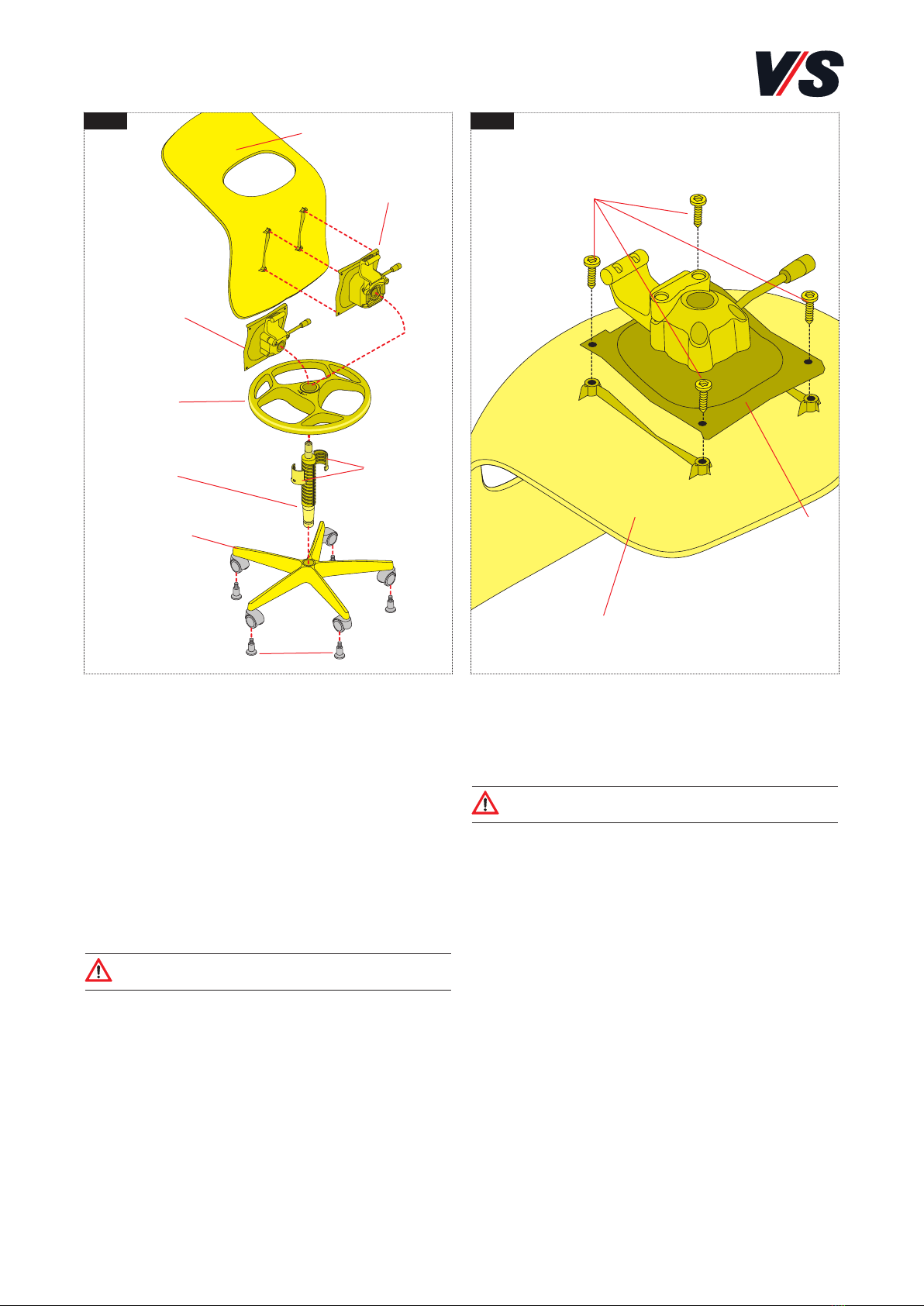
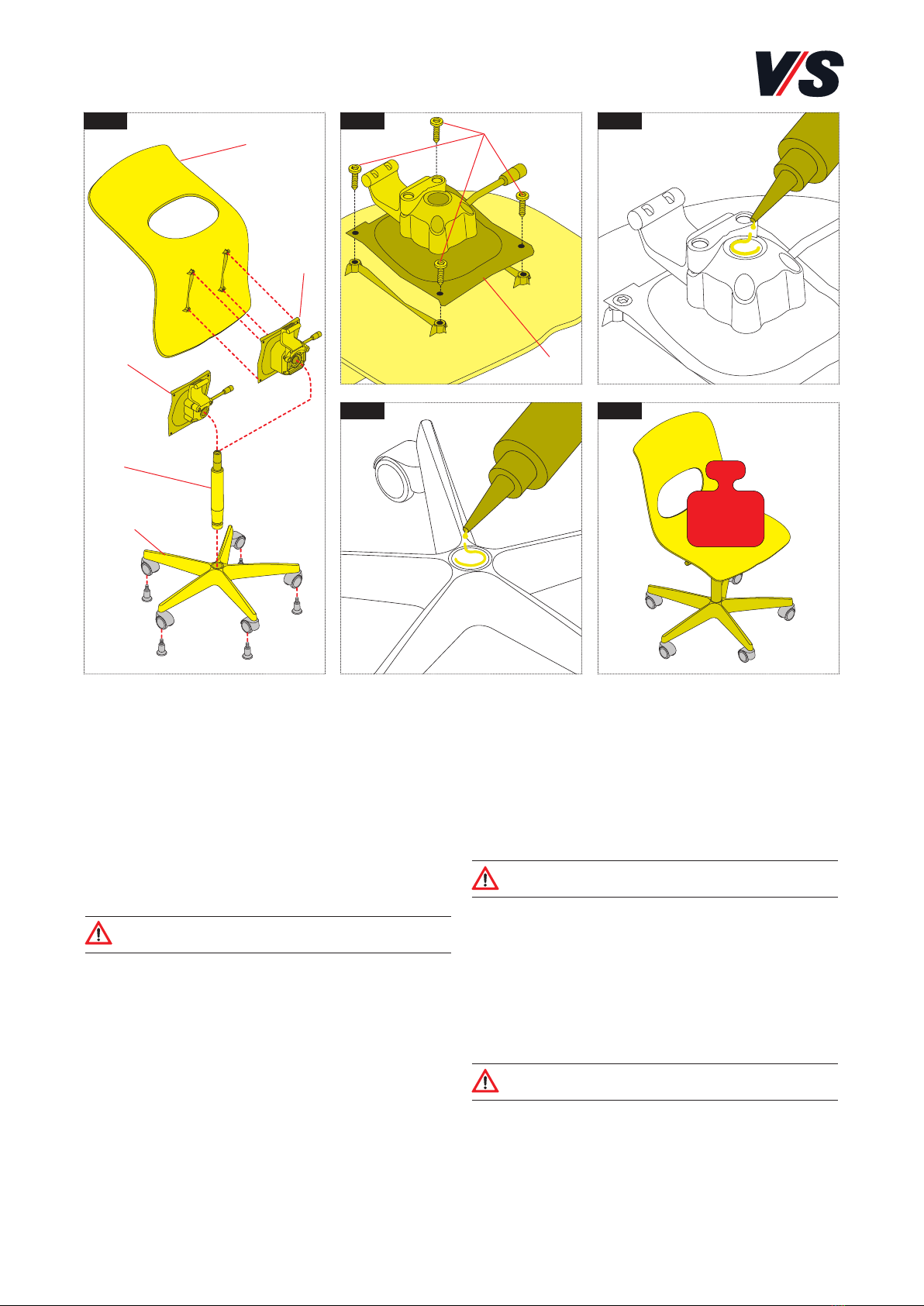
Lieferumfang:
Die Produkte werden teilmontiert ausgeliefert.
Fehlersuche und Service:
Bei eventuell auftretenden Fehlern wenden Sie sich bitte
Wartung und Reinigung:
Im Internet: vs.de/kataloge/reinigung/
Weitergabe/Entsorgung:
Bei Weitergabe des Produkts ist die Anleitungen zu über-
geben. Informationen zur umweltfreundlichen Entsorgung
erhalten Sie bei Ihrer zuständigen Kommune.
MONTAGEANLEITUNG 70-363 V01 000217
NF-Move Export.
Modelle 32500-32510.
1
VS Vereinigte Spezialmöbelfabriken GmbH & Co.KG
http://links.vs-service.com/downloads/70-363_V01_DEEN_NF-Move-Export-100836.pdf
32500 32510

Modell 32500 (Bild 1)
Komponenten:
- Sitzschale (1)
- Sitzträger starr (2.1)
- Sitzträger mit 3D-Wippe (2.2)
- Befestigungsmaterial - 4 Schrauben M6x12 (ohne Bild)
- Gasfeder (3)
- Fußkreuz mit vormontierten Rollen (4.1)
- Fußkreuz mit vormontierten Gleitern (4.2)
- Kleber (ohne Bild)
Achtung! Die Komponenten der verschiedenen
Stühle dürfen nicht untereinander getauscht werden.
Vorbereitung der Montage
Gasfeder (3) am oberen Konus mit geeignetem Reiniger
entfetten.
Verbindung Sitzschale und Sitzträger
(Bild 2)
Sitzträger (2) auf Sitzschale (1) stecken und mit den
beigefügten Schrauben (3) fest verbinden.
Achtung! Das Anzugsmoment der Schrauben
beträgt 5,2 Nm!
Montage der Stuhlkomponenten
(Bild 3/4/5)
Konus des Sitzträgers (Bild 3) und des Fußkreuzes (Bild 4)
reinigen. An beiden Positionen jeweils auf ca. 4-5 cm Länge
den beigefügten Kleber auftragen.
Die Teile zusammenfügen und die Sitzfläche mindestens
5 Sekunden mit 400 N belasten (Bild 5).
Achtung! Der Kleber muss komplett aushärten.
Der Stuhl ist erst nach 24 Stunden voll belastbar.
400 N
2
1 2 3
4 5
(2.2)
(2.1)
(4.1)
(4.2)
(2)
(3)
(1)
(1)
(3)

Modell 31510 (Bild 1)
Komponenten:
- Sitzschale (1)
- Sitzträger starr (2.1)
- Sitzträger mit 3D-Wippe (2.2)
- Befestigungsmaterial - Schrauben M6x12 (ohne Bild)
- Fußring (3)
- Gasfeder mit Führungsrohr (4)
- Adapter (5)
- Fußkreuz mit vormontierten Rollen (6.1)
- Fußkreuz mit vormontierten Gleitern (6.2)
- Kleber (ohne Bild)
Achtung! Die Komponenten der verschiedenen
Stühle dürfen nicht untereinander getauscht werden.
Verbindung Sitzschale und Sitzträger
(Bild 2)
Sitzträger (2) auf Sitzschale (1) stecken und mit den
beigefügtenn Schrauben (3) fest verbinden.
Achtung! Das Anzugsmoment der Schrauben
beträgt 5,2 Nm!
3
1 2
(2.2)
(2.1)
(6.1)
(6.2)
(2)
(3)
(4)
(1)
(1)
(3)
(5)

Gasfeder und Adapter vormontieren
(Bild 1)
Gasfeder (5) in Vorrichtung stellen und ausrichten. Adap-
terhälften (6) ansetzen. Dabei muss die Führungsnut der
Gasfeder im Schlitz des Adapters sichtbar sein und die
Oberkante des Adapters mit dem obersten Loch der Füh-
rungsnut abschließen (Bild 1.1).
Gasfeder und Fußring vormontieren
(Bild 2)
Gasfeder mit Adapter in Vorrichtung setzen und Fußring (4)
aufstecken. Dabei ist der Knopf (8) gedrückt zu halten.
Achtung! Die Markierung auf dem Ring oben muss
in Richtung der Führungsnut zeigen (Bild 2.1).
Der Fußring wird mit ein bis zwei Hammerschlägen auf ein
Überrohr (9) so weit über den Adapter geschoben, bis er
einrastet.
Achtung! Unterseite dieser Baugruppe genau kontrol-
lieren! Zwischen Fußring und Adapter muss ein Versatz
erkennbar sein (Bild 3). Andernfalls den Fußring noch
weiter auf den Adapter schieben.
Montage der Stuhlkomponenten
(Bild 4/5/6)
Gasfeder (5) am oberen Konus mit geeignetem Reiniger
entfetten. Konus des Sitzträgers (Bild 4) und des Fußkreu-
zes (Bild 5) reinigen. An beiden Positionen jeweils auf ca.
4-5 cm Länge den beigefügten Kleber auftragen.
Die Teile fest zusammenfügen und die Sitzfläche mindes-
tens 5 Sekunden mit 400 N belasten) (Bild 6).
Achtung! Der Kleber muss komplett aushärten.
Der Stuhl ist erst nach 24 Stunden voll belastbar.
4
(4)
(8)
(9)
3 4 5
1
(6)
(5)
21.1 2.1
(6)
400 N
6

Intended use:
These chair models have been designed and are suitable for
use in educational establishments. No liability will be as-
sumed for any use other than that intended, for example in
workshops, storage rooms or damp locations. To be used in
closed premises only.
General note on reading and
retaining these Instructions:
Before using the products, read these instructions carefully
and pay special attention to the safety instructions. Keep
these Instructions for future consultation and communicate
them to other users.
General note on safety:
The following symbols and notes are used in these
Instructions:
Important! This symbol indicates an important
assembly note.
Caution! This symbol indicates a very important
note.
On the Web:
These Instructions are also available online for download
via the link indicated at the top of the page.
Standards:
Tested in accordance with DIN EN 1729 - 1/2.
Scope of delivery:
The products are supplied partially assembled.
Faults and service:
If any faults occur, please contact our
Maintenance and cleaning:
On the Internet: vs.de/kataloge/reinigung/en
Transfer/disposal:
If the product is transferred to another party then it must be
accompanied by these Instructions. For information on the
environmentally responsible disposal of the product, please
contact your relevant local authority department.
ASSEMBLY INSTRUCTIONS 70-363 V01 000217
NF-Move Export.
Models 32500-32510.
5
VS Vereinigte Spezialmöbelfabriken GmbH & Co.KG
http://links.vs-service.com/downloads/70-363_V01_DEEN_NF-Move-Export-100836.pdf
32500 32510

Modell 32500 (Figure 1)
Components:
- Seat shell (1)
- Seat support - rigid (2.1)
- Seat support with 3D rocker (2.2)
- Fixing material - 4 M6x12 screws (not pictured)
- Gas spring (3)
- Star foot with pre-mounted castors (4.1)
- Star foot with pre-mounted slide elements (4.2)
- Adhesive (not pictured)
Caution! The components must not be swapped
between the different chairs.
Preparing for assembly
Degrease the top cone of the gas spring (3) using a suitable
cleaning agent.
Fixing the seat shell to the seat support
(Figure 2)
Place the seat support (2) on the seat shell (1) and join
together firmly using the supplied screws (3).
Caution!
The torque of the screws is 5.2 Nm!
Assembling the chair components
(Figures 3/4/5)
Clean the cone of the seat (Figure 3) and the star foot
(Figure 4) Apply the supplied adhesive over a length of
approx. 4-5 cm at both points. Join the parts together and
place a load of 400 N on the seating surface for at least 5
seconds (Figure 5).
Caution! The adhesive must dry thoroughly. Wait for
24 hours before subjecting the chair to its full load.
6
400 N
1 2 3
4 5
(2.2)
(2.1)
(4.1)
(4.2)
(2)
(3)
(1)
(1)
(3)

Modell 31510 (Figure 1)
Components:
- Seat shell (1)
- Seat support - rigid (2.1)
- Seat support with 3D rocker (2.2)
- Fixing material - M6x12 screws (not pictured)
- Foot ring (3)
- Gas spring with guide tube (4)
- Adapter (5)
- Star foot with pre-mounted castors (6.1)
- Star foot with pre-mounted slide elements (6.2)
- Adhesive (not pictured)
Caution! The components must not be swapped
between the different chairs
Fixing the seat shell to the seat support
(Figure 2)
Place the seat support (2) on the seat shell (1) and join
together firmly using the supplied (3).
Caution!
The torque of the screws is 5.2 Nm!
7
1 2
(2.2)
(2.1)
(6.1)
(6.2)
(2)
(3)
(4)
(1)
(1)
(3)
(5)

Pre-assembling the gas spring and
adapter (Figure 1)
Place the gas spring (5) in the mechanism and adjust. At-
tach the halves of the adapter (6) When you do this, the
guide groove of the adapter must be visible in the slot in
the adapter and the top edge of the adapter must be level
with the topmost hole in the guide groove (Figure 1.1).
Pre-assembling the gas spring and foot
ring (Figure 2)
Place the gas spring with the adapter in the mechanism
and position the foot ring (4) on it. When doing this, keep
button (8) pressed in.
Caution! The marking on the top of the ring must
point toward the guide groove (Figure 2.1).
The foot ring is pushed over the adapter until it engages
by striking a surrounding tube (9) once or twice with a
hammer.
Caution! Check the underside of this assembly care-
fully! There must be an identifiable offset between the
foot ring and the adapter (Figure 3). If this is not the
case, push the foot ring further onto the adapter.
Assembling the chair components
(Figures 4/5/6)
Degrease the top cone of the gas spring (5) using a suitable
cleaning agent. Clean the cone of the seat support (Figure
4) and the star foot (Figure 5). Apply the supplied adhesive
over a length of approx. 4-5 cm at both points.
Join the parts together firmly and place a load of 400 N
on the seating surface for at least 5 seconds (Figure 6).
Caution! The adhesive must dry thoroughly. Wait for
24 hours before subjecting the chair to its full load.
8
(4)
(8)
(9)
3 4 5
1
(6)
(5)
21.1 2.1
(6)
400 N
6
This manual suits for next models
1
Table of contents
Languages:
Other VS Indoor Furnishing manuals

VS
VS Level Series User manual

VS
VS 901 Series User manual

VS
VS LIGNOdur Uno-M-Step 22405 User manual

VS
VS Pareto-Twin 21758 User manual

VS
VS Vis-a-Vis Lounge Series User manual

VS
VS 01442-001 User manual

VS
VS 800 Series User manual

VS
VS 31506 User manual

VS
VS JustBe 40630 User manual

VS
VS RondoLift User manual