VS Vis-a-Vis Lounge Series User manual

VS Vereinigte Spezialmöbelfabriken GmbH&Co.KG
http://links.vs-service.com/downloads/70-251_V01_DEEN_Lounge-Vis-a-Vis-103200.pdf
Intended use:
The current seating unit is intended
exclusively for use in office spaces. No liability will
be assumed for any use other than that intended,
e.g in workshops, storage areas or damp locations).
General comments:
Before using the products, read these instructions carefully
and pay special attention to the safety instructions. Keep
these Instructions for future consultation and communicate
them to other users.
General note on safety
The following symbols and notes are used in these
Instructions:
Important! This symbol indicates an important assembly
note.
Caution! This symbol indicates a very
important note.
Bestimmung:
Das vorliegende Sitzmöbel ist ausschließlich für die Nutzung
im Objektbereich konzipiert. Für nicht bestimmungsgemäßen
Einsatz (z.B. in Werkstätten, Lagerbereichen oder Feuchträu-
men) wird keine Haftung übernommen.
Allgemeiner Hinweis:
Lesen Sie diese Anleitung vor Benutzung der Produkte sorg-
fältig und beachten Sie insbesondere auch die Sicherheits-
hinweise. Bewahren Sie die Anleitung zum späteren Nachle-
sen auf bzw. geben Sie diese an andere Benutzer weiter.
Allgemeiner Sicherheitshinweis:
In dieser Anleitung verwenden wir folgende Symbole und
Hinweise:
Wichtig! Bei diesem Symbol handelt es sich um einen
wichtigen Montagehinweis.
Achtung! Bei diesem Symbol handelt es sich um einen
sehr wichtigen Hinweis.
MONTAGEANLEITUNG: 70-251 V01 000819
Serie Lounge
Vis-a-Vis.
ASSEMBLY INSTRUCTIONS: 70-251 V01 000819
Serie Lounge
Vis-a-Vis.
30114-30119
20115-20116
30193-30194

2
Ausstattungsbeispiel
Equipment example
Im Internet:
Diese Anleitung wird Ihnen auch online als Download bereit-
gestellt über den in der Kopfleiste angegebenen Link.
Lieferumfang:
Die Produkte werden teilmontiert ausgeliefert.
Betrieb:
Beachten Sie die Hinweise auf den folgenden Seiten.
Fehlersuche und Service:
Bei eventuell auftretenden Fehlern wenden Sie sich bitte an
Wartung und Reinigung:
Mehr dazu unter: vs.de/kataloge/reinigung/
Weitergabe und Entsorgung:
Bei Weitergabe des Produkts ist auch diese Anleitung zu
übergeben. Für eine umweltfreundliche Entsorgung infor-
mieren Sie sich bitte bei Ihrer zuständigen Kommune.
Die gekennzeichneten E-Komponenten dürfen nicht über
den Hausmüll entsorgt werden.
Sie müssen von dem Möbel getrennt werden, bevor
das Möbel der Entsorgung zugeführt wird.
Die Entsorgung erfolgt an zugelassenen Sammel-
und Rücknahmestellen.
On the Web:
These Instructions are also available online for download via
the link indicated at the top of the page.
Scope of delivery:
The products are supplied partially assembled.
Use:
Please take account of the notes on the following pages.
Faults and service
If any faults occur, please contact the VS Customer Service:
Maintenance and cleaning:
For more information, go to: vs.de/kataloge/reinigung/en
Forwarding and Disposal:
If the product is passed on to any third party then these instruc-
tions
must be supplied with it. Please contact your relevant
local authority for information on environmentally compatible
disposal. The indicated electric and electronic components
must not be disposed of with the ordinary waste.
They must be removed from the furniture unit before
the unit is sent for disposal. They are to be disposed
of at authorized collection and return points.

3
Packen Sie den Mittelblock (1) aus und legen Sie Ihn
auf die Rückseite, so dass die Revisionsöffnung (2) und
die Montageöffnung (3) gut zugänglich sind.
Unpack the centre block (1) and lay it on its back so
that the adjustment opening (2) and the assembly
opening (3) are easily accessible.
Montieren Sie die beiden Haltelaschen (4) für die Blende
mit vier Schrauben (4,0 x 16 PH) diagonal in den beiden
oberen Ecken der Revisionsöffnung. Drücken Sie dann die
beiden Magnete (5) in die Revisionsblende (6).
Using four screws (4.0 x 16 PH), fix the two retaining
plates (4) for the cover diagonally in the top two cor-
ners of the adjustment opening. Then press the two
magnets (5) into the adjustment cover (6).
Befestigen Sie die beiden Zugentlastungen (7) wie abge-
bildet mit jeweils zwei Schrauben (3,0 x 15 SK).
Fix the two strain relief mechanisms (7) as shown us-
ing two screws each (3.0 x 15 hexagon).
Montieren Sie die 3fach-Steckdose (8) innen an der Rück-
wand des Mittelblocks mit doppelseitigem Klebeband.
Install the 3-way socket (8) on the inside at the back
wall of the centre block using a double-sided adhesive
strip.
Optional: Montage der Steckdose. Montieren Sie zu-
nächst die Steckdosenblende (9) und befestigen Sie diese
mit zwei Schrauben (3,0 x 15 SK) (10). Entfernen Sie an-
schließend die rote Montagesicherungen (11) von der
Steckdose (12) und klicken Sie die Steckdose von innen in
die Steckdosenblende ein.
Optional: Install the socket. First of all, install the
socket cover (9) and fix it in place using two screws
(3.0 x 15 hexagon) (10). Then remove the red installa-
tion protections (11) from the socket (12) and snap
the socket from the inside into the socket cover.
DE
EN
DE
EN
DE
EN
DE
EN
DE
EN
1. Montage der Sitzgruppe Vis-a-Vis 30114-30119, 20115-20116
Assembling the Vis-a-Vis seating group 30114-30119, 20115-20116
1.1
(1)
(2)
(3)
(4)
1.2
(5)
(6)
(7)
1.3
(8)
1.4
(9)
(11)
(12)
(10)
1.5

4
1.6
1.7
1.8
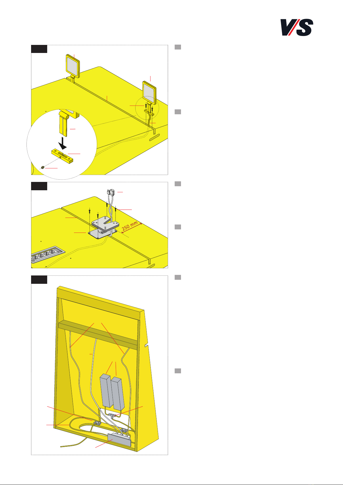
Optional: Montage der LED-Beleuchtung. Montieren
Sie die Anschraublasche (13) mit dem Gewindestift (14)
an die LED-Lampe (15). Führen Sie die Zuleitung (16)
über den Schlitz in der Funktionsfuge (17) in den Mittel-
block ein. Richten Sie die Lampe so aus, dass die Außen-
kante des Lampenschirms bündig mit der Seitenwand
des Mittelblocks ist und befestigen Sie die Lampe mit
zwei Schrauben (4,5 x 35 PH) (18) in der Funktionsfuge.
Optional: Install the LED lighting. Fix the screw plate
(13) to the LED lamp (15) using the threaded pin (14).
Guide the supply line (16) through the slot in the func-
tional gap (17) into the centre block. Orient the lamp
in such a way that the outside edge of the lamp frame
is flush with the side wall of the centre block and fix
the lamp in the functional gap using two screws (4.5 x
35 PH) (18).
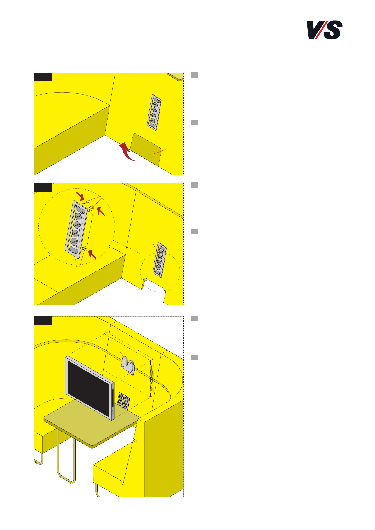
Optional: Montage des Monitorhalters. Positionieren
Sie den Monitorhalter (19) mit vier Schrauben (5,0 x 15
SK) (20) mittig über die Funktionsfuge (17). Führen Sie
die Zuleitung (21) über den Schlitz in der Funktionsfuge
in den Mittelblock ein.
Optional: Assemble the monitor holder. Position the
monitor holder (19) centred above the functional gap
(17) using four screws (5.0 x 15 SK) (20). Guide the
supply line (21) through the slot in the functional gap
into the centre block.
Verkabelung: Stecken Sie das Kabel zur Stromzufuhr
(22) mit einem GST18-Stecker an die 3fach Steckdose
am Boden und sichern Sie es mit einer Zugentlasung (4).
Verbinden Sie die beiden Steckdosen (23) über ein
GST18 T-Stück (24) mit einem GST-Stecker auf der an-
deren Seite der 3fach-Steckdose. Bei nur einer Steck-
dose (23) entfällt das T-Stück.
Stecken Sie die Netzteile der Leuchten (25) und den
Kaltgerätestecker des Monitors (26) in die 3 Dosen der
3fach-Steckdose (8). Weitere Verkabelungen (wie USB-
Anschlüsse) können auch später über die Revisionsöff-
nung vorgenommen werden.
Cabling: Plug the cable to the power supply (22) with
a GST18 connector to the 3-way socket on the base
and secure it using a strain-relief mechanism (4). Con-
nect the two sockets (23) via a GST18 T-piece (24)
with a GST connector on the other side of the 3-way
socket. If there is only one socket (23) then the T-piece
is not used.
Plug in the power supply units for the lamps (25) as
well as the cold-device plug for the monitor (26) into
the 3 sockets in the 3-way socket strip (8). Further ca-
bling (such as USB connections) can also be performed
subsequently via the adjustment opening
DE
EN
DE
EN
DE
EN
(13)
(14)
(15)
(15)
(15)
(17)
(16)
(18)
(21)
(19)
(17)
(22)
(23)
(26)
(4)
(8)
(24)
(25)
(20)

5
1.9
(29)
(30)
1.11
1.10
(33)
(34)
1.12
Verkettung: Befestigen Sie die Querstrebe zur Verket-
tung (27),indem Sie drei Gewindeschrauben (M6 x 40)
(28) mit Unterlegscheiben in die dafür vorgesehenen
Gewindebuchsen am Boden des Mittelblocks schrauben.
Joining: Fix the cross-strut to the joining element (27).
To do this, screw the three threaded screws (M6 x 40)
(28) with washers into the threaded bushes provided
for this purpose in the base of the centre block.
Packen Sie die beiden Highbackelemente aus, an denen
der Mittelblock befestigt werden soll. Entfernen Sie die
Abdeckkappen (29) an Riegeln in den Lehnen und de-
montieren Sie das Verbindungsset (30) an der Unter-
seite.
Unpack the two high-back elements to which the cen-
tre block is to be fixed. Remove the covers (29) at the
sides of the backrests and dismount the connecting set
(30) on the underside.
Legen Sie eines der Highbackelemente neben den Mit-
telblock. Verriegeln Sie mit dem Innensechskantschlüs-
sel SW 7 (31) aus dem Beipack beide Elemente durch
die Öffnung im Polster miteinander (links drehen!).
Verschrauben Sie anschließend die Querstrebe (27) mit
zwei Gewindeschrauben (M6 x 40) (32) und Unter-
legscheiben mit dem Highbackelement. Verfahren Sie
mit dem Highbackelement auf der anderen Seite in
gleicher Weise. Verschließen Sie die Revisionsöffnung
mit der Revisionsklappe (9).
Place one of the high-back elements against the centre
block. Lock the two elements together through the
opening in the upholstery (turn to the left!) using the
size 7 Allen key (31) from the accessories pack. Then
use two threaded screws (M6 x 40) (32) with washers
to screw the cross-strut (27) to the high-back element.
Proceed in the same way for the high-back element on
the other side. Block the adjustment opening using the
adjustment flap (9).
Montage des Tisches: Drehen Sie vier Gewindebolzen
(M6 x 50) (33) in den Tischbügel (34) ein. Schlitzen
Sie anschließend den Stoff im Bereich der Lochung
senkrecht auf.
Assembling the table: Screw the four threaded bolts
(M6 x 50) (33) into the table bracket (34). Then cut
the fabric in the area of the hole vertically.
DE
EN
DE
EN
DE
EN
DE
EN
(27)
(27)
(32)
(9)
(31)
(28)

6
Stecken Sie das Gestell mit den vier Gewindebolzen in
den Mittelblock ein und fixieren Sie es von innen mit
vier Muttern M6 (35) und Unterlegscheiben (36). Ver-
schließen Sie dann die Revisionsöffnung mit der Revi-
sionsklappe (9). Stellen Sie anschließend den komplet-
ten Verbund auf.
Insert the frame with the four threaded bolts into the
centre block and fix it from inside with four M6 nuts
(35) and washers (36). Then block the adjustment
opening using the adjustment flap (9). Next stand the
entire connected assembly upright.
Anbringen weiterer Elemente: Sollen noch weitere High-
backelemente an das Ensemble angeschlossen werden,
entfernen Sie zunächst die Abdeckkappen (29) und klap-
pen die Verbinder (30) aus.
Attaching other elements: If it is necessary to fix oth-
er high-back elements to the assembled unit, first re-
move the covers (29) and fold out the connectors (30).
Schieben Sie dann die Elemente zusammen, so dass die
Verbinder (30) in das Gegenstück einrasten. Verriegeln
Sie mit dem Innensechskantschlussel SW 7 (31) aus
dem Beipack die Elemente durch die Öffnung im Polster
miteinander (links drehen!).
Achtung! Wird die Kombination verschoben, können
die Beschläge ausreißen.
Then push the elements together so that the connec-
tors (30) engage in the corresponding counterpieces.
Lock the elements together through the opening in the
upholstery (turn to the left!) using the size 7 Allen
key (31) from the accessories pack.
Caution! If the assembly is pushed then the fixings
may be torn out.
Ausgleichen von Bodenunebenheiten: Bei Bodenun-
ebenheiten lösen Sie die Schrauben (37) an den Stand-
kufen der Sitzelemente mit Innensechskantschlussel
SW 5. Stellen Sie die Ausgleichskeile (38) ein (gegenei-
nander versetzen) und drehen Sie die Schrauben wieder
fest. (Bei der maximalen Verstellung muss die Schraube
komplett herausgedreht werden.)
Compensating for uneven floors: If the floor is un-
even, release the screws (37) at the base skids of the
seating elements using a size 5 Allen key. Adjust the
levelling wedges (38) (adjust in alternation) and tight-
en the screws again. (At maximum adjustment, the
screw must be completely extended.)
DE
EN
DE
EN
DE
EN
DE
EN
(29)
(30)
(30)
(37)
(38)
(31)
1.13
1.14
(36)
(35)
(9)
1.15
1.16

7
Revisionsklappe: Im Mittelblock ist eine Revisions-
klappe (39) integriert, die einen Zugang zur innen-
liegenden Verkabelung ermöglicht. Die Klappe ist mit
Magneten befestigt und kann leicht von unten
abgenommen werden.
Adjustment flap: The centre block contains an adjust-
ment flap (39) that makes it possible to access the in-
ternal cabling. The flap is held in place by magnets and
is easy to remove from below.
Verkabelung: Zur Verkabelung (USB, HDMI, CAT) kön-
nen die integrierten Steckdosenleisten (40) von innen
entfernt werden. Drücken Sie hierzu die Halteklammern
(41) an den Enden der Steckdosenleiste zusammen und
ziehen dann die Steckdosenleiste nach innen.
Cabling: The integrated socket strips (40) can be re-
moved from the inside for cabling purposes (USB, HDMI,
CAT). To do this, press the retaining clamps (41) at the
ends pf the socket strip together and then pull the
socket strip inwards.
Montieren eines Monitors: Zum Montieren eines Bild-
schirms am dafür vorgesehenen Monitorhalter (42),
folgen Sie bitte den Anweisungen der beiliegenden Be-
dienanleitung des Herstellers.
Mounting a monitor: To mount a screen at the moni-
tor holder available for this purpose (42), please follow
the instructions in the enclosed manufacturer’s Operat-
ing Instructions.
DE
EN
DE
EN
DE
EN
2. Bedienung und weitere Funktionen
Assembling the Vis-a-Vis seating group
2.1
2.2
(39)
(40)
(41)
(41)
2.3
(42)

8
Table of contents
Other VS Indoor Furnishing manuals

VS
VS Shift+ Landscape Cabinet modules User manual

VS
VS OfficeBox 40500-05 User manual

VS
VS LIGNOdur Uno-M-Step 22405 User manual

VS
VS Pareto-Twin 21758 User manual

VS
VS StepByStep-I User manual

VS
VS TriTable-II User manual

VS
VS 21707 Manual

VS
VS RondoLift User manual

VS
VS NF-Move Export 32500 User manual

VS
VS Level Series User manual