VWR TD142 User manual

H76.0.24.6C-01_VWR
TD142
Quick-Response Thermometer
INSTRUCTION MANUAL
European Catalogue Number(s):
620-2664
Version: 1
Issued: 21.02.2018

H76.0.24.6C-01_VWR Operating Manual TD142 page 2 of 16
_____________________________________________________ _____________________________________________________________________________
Legal Address of Manufacturer
Europe
VWR International bvba
Researchpark Haasrode 2020
Geldenaaksebaan 464
B-3001 Leuven
+ 32 16 385011
http://be.vwr.com
Country of origin
Germany

H76.0.24.6C-01_VWR Operating Manual TD142 page 3 of 16
_____________________________________________________ _____________________________________________________________________________
Index
1GENERAL NOTE............................................................................................................... 3
2SAFETY ............................................................................................................................... 4
2.1 INTENDED USE.................................................................................................................. 4
2.2 SAFETY SIGNS AND SYMBOLS............................................................................................ 4
2.3 SAFETY GUIDELINES ......................................................................................................... 5
3PRODUCT SPECIFICATION .......................................................................................... 6
3.1 SCOPE OF DELIVERY.......................................................................................................... 6
3.2 OPERATION AND MAINTENANCE ADVICE........................................................................... 6
4HANDLING......................................................................................................................... 7
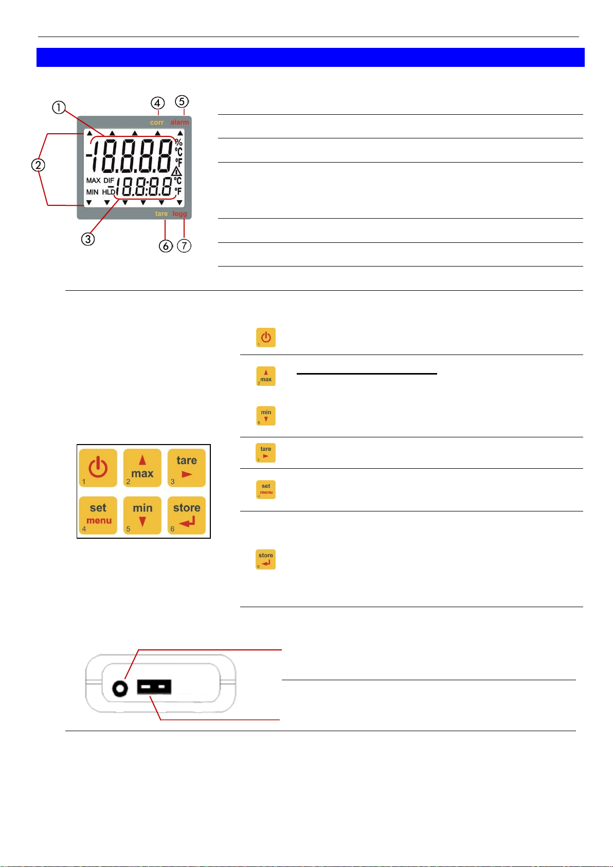
4.1 DISPLAY ........................................................................................................................... 7
4.2 BASIC OPERATION ............................................................................................................ 7
4.3 CONNECTIONS................................................................................................................... 7
4.4 POP-UP CLIP ...................................................................................................................... 8
5START OPERATION ........................................................................................................ 8
6DEVICE CONFIGURATION ........................................................................................... 9
7REMARKS TO SPECIAL FEATURES.........................................................................10
7.1 BASE ADDRESS (’ADR.’)................................................................................................. 10
7.2 POWER OFF TIME ............................................................................................................ 10
8OUTPUT ............................................................................................................................11
8.1 SERIAL INTERFACE ......................................................................................................... 11
9ADJUSTMENT ................................................................................................................. 12
9.1 ZERO DISPLACEMENT ..................................................................................................... 12
9.2 SCALE CORRECTION ....................................................................................................... 12
9.3 CORRECTION FOR SURFACE MEASURING ......................................................................... 12
10 FAULT AND SYSTEM MESSAGES ..........................................................................13
11 SPECIFICATION ..........................................................................................................13
12 TECHNICAL SERVICE...............................................................................................15
13 WARRANTY..................................................................................................................15
14 EQUIPMENT DISPOSAL ............................................................................................ 15
1 General Note
Read this document carefully and get used to the operation of the device before you
use it. Keep this document within easy reach near the device for consulting in case
of doubt.

H76.0.24.6C-01_VWR Operating Manual TD142 page 4 of 16
_____________________________________________________ _____________________________________________________________________________
2 Safety
2.1 Intended Use
This device is designed for temperature measurement.
You can plug in a thermocouple sensor with Miniature-DIN-plug.
The device features a lot of useful features as for example hold, correction factor for
surface measurement, interface etc.
Personnel which starts up, operates and maintains the device has to have sufficient
knowledge of the measuring procedure and the meaning of the resulting measured
values, this manual delivers a valuable help for this. The instructions of the manual
have to be understood, regarded and followed.
To be sure that there´s no risk arising due to misinterpretation of measured values,
the operator must have further knowledge in case of doubt - the user is liable for any
harm/damage resulting from misinterpretation due to insufficient knowledge.
The manufacturer will assume no liability or warranty in case of usage for other
purpose than the intended one, ignoring this manual, operating by unqualified staff as
well as unauthorized modifications to the device.
The safety requirements (see below) have to be observed.
The device must be used only according to its intended purpose and under suitable
conditions.
Use the device carefully and according to its technical data
(do not throw it, strike it, …). Protect the device from dirt.
2.2 Safety signs and symbols
Warnings are labelled in this document with the followings signs:
Caution! This symbol warns of imminent danger, death, serious
injuries and significant damage to property at non-observance.
Attention! This symbol warns of possible dangers or dangerous
situations which can provoke damage to the device or environment at
non-observance.
Note! This symbol point out processes which can indirectly influence
operation, possibly cause incorrect measurement or provoke
unforeseen reactions at non-observance.

H76.0.24.6C-01_VWR Operating Manual TD142 page 5 of 16
_____________________________________________________ _____________________________________________________________________________
2.3 Safety guidelines
This device has been designed and tested in accordance with the safety regulations
for electronic devices.
However, its trouble-free operation and reliability cannot be guaranteed unless the
standard safety measures and special safety advises given in this manual will be
adhered to when using the device.
1. Trouble-free operation and reliability of the device can only be guaranteed if the
device is not subjected to any other climatic conditions than those stated under
chapter 11 Specification.
2. If there is a risk whatsoever involved in running it, the device has to be
switched off immediately and to be marked accordingly to avoid re-
starting.
Operator safety may be a risk if:
- there is visible damage to the device
- the device is not working as specified
- the device has been stored under unsuitable conditions for a longer
time. In case of doubt, please return device to manufacturer for repair
or maintenance.
3. Do not use these products as safety or emergency stop devices or in
any other application where failure of the product could result in
personal injury or material damage.
Failure to comply with these instructions could result in death or serious
injury and material damage.
4. This device must not be used at potentially explosive areas! The usage
of this device at potentially explosive areas increases danger of
deflagration, explosion or fire due to sparking.
5. This device is not constructed for use in medical applications.
6. This device must not be run with a defective or damaged power supply
unit. Danger to life due to electrical shock!
7. Temperature sensor:
There is a risk of stitch injury by using insertion probs. When measuring
high temperatures there is a risk of burn, also due to residual heat of
the sensor tube.
8. Consider when measuring in food:
The device housing is not construed for the permanent contact with
food.
Keep in mind to use temperature-probes witch are suitable for the use
in food only.

H76.0.24.6C-01_VWR Operating Manual TD142 page 6 of 16
_____________________________________________________ _____________________________________________________________________________
3 Product Specification
3.1 Scope of delivery
The scope of supply includes:
Device with battery
Operating manual
3.2 Operation and maintenance advice
Battery operation:
If ‘bAt’ is shown in the lower display the battery has been used up and needs to be
replaced. However, the device will operate correctly for a certain time. If ‘bAt’ is
shown in the upper display the voltage is too low to operate the device; the battery
has been completely used up.
The battery has to be taken out, when storing device above 50 °C.
We recommend taking out battery if device is not used for a longer
period of time.
After recommissioning the real-time clock has to be set again.
Mains operation with power supply
When using a power supply please note that operating voltage has to be
10.5 to 12 V DC.
Do not apply overvoltage!! Cheap 12V-power supplies often have
excessive no-load voltage.
We, therefore, recommend using regulated voltage power supplies.
Trouble-free operation is guaranteed by our power supply PS100.
Prior to connecting the power supply to the mains, make sure that the operating
voltage stated at the power supply is identical to the mains voltage.
Treat device and sensor carefully. Use only in accordance with above specification.
(do not throw, hit against etc.). Protect plug and socket from soiling.
Connecting/changing sensors
To disconnect thermocouple sensor plug do not pull at the cable but at the
plug
Selection of types of thermocouples: Prior to carrying out a
measurement make sure to check if device is set to the thermocouple
type used (type is shown on the display shortly after unit has been
switched on). Unless the correct thermocouple is set, temperature
measurements will be incorrect!

H76.0.24.6C-01_VWR Operating Manual TD142 page 7 of 16
_____________________________________________________ _____________________________________________________________________________
4 Handling
4.1 Display
1
Main display: measuring value
2
Arrows show display options
3
Secondary display: display of min/max, hold
4
corr: appears if offset- , scale correction or
correction for surface measurement is <> state of
delivery.
5
alarm: not in use
6
tare: not in use
7
logg: not in use
4.2 Basic Operation
On / Off
+
min/max measuring:
press short: shows the min./max. value
press again: hides min./max. value
press 2 sec.: clears particular value
not in use at this device type
Set/Menu:
press long: calling of configuration
Store/Quit:
press short: hold-function, the last
measuring value will be held
in the secondary display.
press again: hides the value
4.3 Connections
Output: Connection for optically isolated
interface adapter
Sensor Connection
Power supply: the mains adapter socket is located at the left side of the
device.

H76.0.24.6C-01_VWR Operating Manual TD142 page 8 of 16
_____________________________________________________ _____________________________________________________________________________
4.4 Pop-up clip
Handling:
•Pull at label “open” in order to swing open the pop-up clip.
•Pull at label “open” again to swing open the pop-up clip further.
Pop-up clip closed
Pop-up clip at position 90°
Pop-up clip at position 180°
Function:
• The device with a closed pop-up clip can be plainly laid onto a table or attached to a belt, etc.
• The device with pop-up clip at position 90° can be set up on a table, etc.
• The device with pop-up clip at position 180° can be suspended from a screw.
Device attached to a belt
Device set up on a table
Device suspended
5 Start Operation
Connect sensor and turn on device via key.
After segment test the device displays some configuration:
• If the surface correction factor is adjusted, the display will show
„SCF.“ and its value shortly.
After that, the device is ready for measuring.

H76.0.24.6C-01_VWR Operating Manual TD142 page 9 of 16
_____________________________________________________ _____________________________________________________________________________
6 Device Configuration
To change device settings, press Set (key 4) for 2 seconds. This will call the
configuration menu.
The parameters can be changed with (key 2) or (key 5).
Press Set again to go to the next setting.
Store (key 6) finishes the configuration and returns to standard measuring operation.
Parameter
Values
Meaning
MENU
KEY or
tYPE
ni.cr
J
S
T
N
B
E
Selection Thermocouple:
Type K: NiCr-Ni
Type J: Fe-CuNi
Type S: Pt10Rh-Pt
Type T: Cu-CuNi
Type N: NiCrSi-NiSi
Type B: Pt30Rh-Pt6Rh
Type E: NiCr-CuNi
rES
0.1°
Resolution: 0,1°C or °F
1°
Resolution: 1°C or °F
Unit
°C
Values in °C
°F
Values in °F
P.oFF
1-120
Auto Power Off time in minutes
oFF
Auto Power Off deactivated
Out
oFF
Function of the output: No output function, lowest
power consumption
SEr
Output is serial interface
Adr.
01,11..91
Base address of interface (if Out = SEr)
OFS.
-10.0°C..10.0°C or
-18.0°F..10.0°F
The offset of sensor will be displaced by this value to
compensate for deviations in the Sensor or in the
measuring device.
oFF:
Zero point displacement is deactivated (=0.0°)
SCL.
-5.00..5.00 %
The measuring scale of sensor will be changed by
this factor [%] to compensate deviations of
temperature probe or measuring device.
oFF:
Correction factor is deactivated (=0.000)
SCF.
0.950..1.200
Correction value for surface measurement of sensor 1.
(related to ambient temperature of the measuring
device)
See chapter 9.3 Correction for surface measuring
oFF:
Surface correction factor is deactivated (=1.000)

H76.0.24.6C-01_VWR Operating Manual TD142 page 10 of 16
_____________________________________________________ _____________________________________________________________________________
7 Remarks To Special Features
7.1 Base Address (’Adr.’)
Using the mullti interface converter it is possible to connect several instruments to a
single interface. As a precondition the base addresses of all devices must not be
identical. In case several devices will be connected via one interface make sure to
configure the base addresses accordingly.
7.2 Power off Time
If there won’t be pressed any key and no interface communication takes place for the
time of the power off time setting (P.Off), the device will be switched off automatically
to save battery power.
If P.oFF = oFF then the automatic switch off is deactivated.

H76.0.24.6C-01_VWR Operating Manual TD142 page 11 of 16
_____________________________________________________ _____________________________________________________________________________
8 Output
The output can be used as serial interface (for suitable interface adapters).
If none of both is needed, we suggest to switch the output off, because battery life
then is extended.
8.1 Serial Interface
By means of the serial interface and a suitable electrically isolated interface
adapter (USB 3100, USB 3100 N, GRS 3100) the device can be connected to a
computer for data transfer.
To avoid transmission errors, there are several security checks implemented e.g.
CRC.
The device has 1 channel:
-Channel 1: current measuring value
Note: The measuring - and display range values read back from the interface
are always in the selected measurement unit!
Supported interface functions
Channel
Code
Function
1
x
0
Read measurement value
x
3
Read system state
x
12
Read ID number
x
174
Delete min. value
x
175
Delete max. value
x
176
Read min measuring range
x
177
Read max measuring range
x
178
Read measuring range unit
x
179
Read measuring range decimal point
x
180
Read kind of measuring of sensor
x
194
Set display unit
x
195
Set decimal point in display
x
199
Read kind of measuring of display
x
200
Read min display range
x
201
Read max display range
x
202
Read display range - unit
x
204
Read display range - decimal point
x
208
Read # of channels
x
214
Read scale correction
x
215
Set scale correction
x
216
Read offset correction
x
217
Set offset correction
x
218
Read correction factor for surface measurement
x
219
write correction factor for surface measurement
x
240
Reset
x
254
Program version

H76.0.24.6C-01_VWR Operating Manual TD142 page 12 of 16
_____________________________________________________ _____________________________________________________________________________
9 Adjustment
9.1 Zero Displacement
A zero displacement can be carried out for the measured value:
value displayed = value measured - offset
Standard setting: 'off' = 0.0°, i.e. no zero displacement will be carried out. Together
with the scale correction (see below) this factor is mainly used to compensate for
sensor deviations. Input is in the display unit.
9.2 Scale Correction
This setting influences the scale of the measuring (factor is in %):
displayed value = measured value * (1+Scal/100)
Standard setting: 'off' =0.000, i.e. value is not corrected. Together with the zero
displacement (see above) this factor is mainly used to compensate for sensor
deviations.
9.3 Correction for surface measuring
The correction value refers to the temperature difference between the device- /
ambient temperature and the temperature determined by the thermocouple.
display = device temperature + (measured temperature –device temperature) * Corr
Standard setting: ’off’ =1.000
This factor is used to compensate for losses of transfer in case of surface
measurements, occurring if the object to be measured is extremely hot but will be
cooled by lower ambient temperatures. The same can be true for sensors with a large
mass. Unless ’off’ is set, this value will be displayed shortly after the device is
switched on; during operation it will be identified by means of the Corr-arrow in the
display

H76.0.24.6C-01_VWR Operating Manual TD142 page 13 of 16
_____________________________________________________ _____________________________________________________________________________
10 Fault and System Messages
Display
Meaning
What to do?
Low battery power, device will only
continue operation for a short period of
time
Replace battery
Battery empty
Replace battery
Mains operation without battery: wrong
voltage
Check power supply, replace it when
necessary
No sensor connected
Connect sensor
Connected sensor or device defective
If 2nd sensor available, check if device is ok.
Return defective device/sensor to
manufacturer for repair
Value extremely out of measuring range
Check: right thermocouple selected.
No display or
confused
characters,
device does not
react on
keypress
Battery empty
Replace battery
Mains operation: wrong voltage or polarity
Check power supply, replace it when
necessary
System error
Disconnect battery and power supplies, wait
shortly, then reconnect
Device defective
Return to manufacturer for repair
Err.1
Measured value above allowable range
Check: correct thermocouple selected.
Temperature not within sensor range?
-> measuring value to high!
Sensor defective
Return to manufacturer for repair
Err.2
Measured value below allowable range
Check: correct thermocouple selected.
Temperature not within sensor range?
-> measuring value to low!
Sensor defective
Return to manufacturer for repair
Err.3
Display range overflow
Check: value above 1999.9 -> too high to be
displayed
Err.4
Display range underflow
Check: value below -1999.9 (Tara?) -> too
low
Er.11
Value could not be calculated
A value, that is necessary for the calculation,
is not available (no sensor) or faulty (over- /
underflow
Calculation overflow happened
Choose different unit
Err.7
System error
Check allowed working temperature of the
device
Return to manufacturer for repair
11 Specification
Thermocouples: J, K, N, S, T, E, B
Resolution: 0.1°C or 1°C 0.1°F or 1°F
Measuring range:
Type K (NiCr-Ni): -220.0 ... +1372.0 °C -364.0 ... +2502.0 °F (*
Type J (Fe-CuNi): -200.0 ... +1100.0 °C -328.0 ... +2021.0 °F (*
Type T (Cu-CuNi): -200.0 ... +400.0 °C -328.0... +752.0 °F
Type N (NiCrSi-NiSi): -200.0 ... +1300.0 °C -328.0 ... +2372.0 °F (*
Type S (Pt10Rh-Pt): -50.0 ... +1768.0 °C -58.0 ... +3215.0 °F (*
Type E (NiCr-CuNi): -60.0 ... +850.0 °C -76.0 ... +1562.0 °F
Type B (
Pt30Rh-Pt6Rh
): +300 ... +1750 °C +572 ... +3182 °F (*
*) values via interface, the device displays up to 1999.9 °F

H76.0.24.6C-01_VWR Operating Manual TD142 page 14 of 16
_____________________________________________________ _____________________________________________________________________________
Accuracy: (for thermocouples acc. to DIN EN 60584) ±1digit
(at nominal temperature ± 5K)
Type J, K, N, T, E: ± (0.5 °C + 0.2 % of measured value)
Type S, B: ± (0.8 °C + 0.4 % of measured value)
Temperature drift: 0.01 %/K
Point of comparison: ±0.3 °C
Nominal temperature: 25 °C
Measuring rate: 4 meas./sec
Sensor connection: connection socket for miniature DIN-plug type K
Display: Two 4 ½ digit LCDs (12.4 mm high and 7 mm high) for
measuring values, and for min/ max memories, hold function,
etc. as well as additional functional arrows.
Pushbuttons: 6 membrane keys
Output: 3.5 mm audio plug, stereo
Output function: serial interface
Interface: Serial interface (3.5mm jack) can be connected to USB or
RS232 interface of a PC via suitable electrically isolated
interface adapter.
Power supply: 9V battery (included in scope of supply)
as well as additional d.c. connector (diameter of internal pin
1.9 mm) for external 10.5-12V direct voltage supply.
(suitable power supply: GNG10/3000)
Power consumption: approx. 1.0 mA (Output „out“ = off)
approx. 1.4 mA (Output „out“ = ser)
Low battery warning: ' bAt '
Working conditions: -25 ... +50 °C, 0 ... 95 %RH (not condensing)
Storage temperature: -25 ... +70 °C
Housing: impact-resistant ABS, membrane keyboard, transparent
panel, Front side IP65
Dimensions: 142 x 71 x 26 mm (L x W x D)
Weight: approx. 155 g
EMC: The instruments confirm to following European Directives:
2014/30/EU EMC Directive
2011/65/EU RoHS
Applied harmonized standards:
EN 61326-1 : 2013 emissions level: class B
emi immunity according to table 3
and A.1
Additional fault: <1%
EN 50581 : 2012

H76.0.24.6C-01_VWR Operating Manual TD142 page 15 of 16
_____________________________________________________ _____________________________________________________________________________
12 Technical service
Web Resources
Visit the VWR website at vwr.com for:
• Complete technical service contact information
• Access to the VWR Online Catalogue, and information about accessories and related products
• Additional product information and special offers
Contact us For information or technical assistance contact your local VWR representative or
visit.vwr.com.
13 Warranty
VWR warrants that this product will be free from defects in material and workmanship for a period of
two (2) years from date of delivery. If a defect is present, VWR will, at its option and cost, repair,
replace, or refund the purchase price of this product to the customer, provided it is returned during
the warranty period. This warranty does not apply if the product has been damaged by accident,
abuse, misuse, or misapplication, or from ordinary wear and tear. If the required maintenance and
inspection services are not performed according to the manuals and any local regulations, such
warranty turns invalid, except to the extent, the defect of the product is not due to such non
performance.
Items being returned must be insured by the customer against possible damage or loss. This
warranty shall be limited to the aforementioned remedies.
IT IS EXPRESSLY AGREED THAT THIS WARRANTY WILL BE IN LIEU OF ALL WARRANTIES
OF FITNESS AND IN LIEU OF THE WARRANTY OF MERCHANTABILITY.
14 Equipment disposal
This equipment is marked with the crossed out wheeled bin symbol to indicate that this equipment
must not be disposed of with unsorted waste.
Instead it's your responsibility to correctly dispose of your equipment at lifecycle -end by handling it
over to an authorized facility for separate collection and recycling. It's also your responsibility to
decontaminate the equipment in case of biological, chemical and/or radiological contamination, so
as to protect from health hazards the persons involved in the disposal and recycling of the
equipment.
For more information about where you can drop off your waste of equipment, please contact your
local dealer from whom you originally purchased this equipment.
By doing so, you will help to conserve natural and environmental resources and you will ensure that
your equipment is recycled in a manner that protects human health.
Thank you

H76.0.24.6C-01_VWR Operating Manual TD142 page 16 of 16
_____________________________________________________ _____________________________________________________________________________
Your Distributor
Austria
VWR International GmbH
Graumanngasse 7
1150 Vienna
Tel.: +43 01 97 002 0
Belgium
VWR International bvba
Researchpark Haasrode 2020
Geldenaaksebaan 464
3001 Leuven
Tel.: +32 016 385 011
China
VWR International China Co., Ltd
Shanghai Branch
Room 256, No. 3058 Pusan Road
Pudong New District
Shanghai 200123
Tel.:+86-21-5898 6888
Fax:+86-21-5855 8801
Czech Republic
VWR International s. r. o.
Veetee Business Park
Pražská 442
CZ - 281 67 Stříbrná Skalice
Tel.: +420 321 570 321
Denmark
VWR International A/S
Tobaksvejen 21
2860 Søborg
Tel.: +45 43 86 87 88
Finland
VWR International Oy
Valimotie 9
00380 Helsinki
Tel.:+358 09 80 45 51
France
VWR International S.A.S.
Le Périgares –Bâtiment B
201, rue Carnot
94126 Fontenay-sous-Bois cedex
Tel.: 0 825 02 30 30* (national)
Tel.: +33 (0) 1 45 14 85 00
(international)
* 0,18 € TTC/min
Germany
VWR International GmbH
Hilpertstraße 20a
D - 64295 Darmstadt
Freecall: 0800 702 00 07
Tel.: +49 (0) 6151 3972 0 (international)
Hungary
VWR International Kft.
Simon László u. 4.
4034 Debrecen
Tel.: +36 (52) 521-130
India
VWR Lab Products Private Limited
No.139. BDA Industrial Suburb,
6th Main, Tumkur Road, Peenya Post,
Bangalore, India –560058
Tel.: +91-80-28078400
Ireland / Northern Ireland
VWR International Ltd / VWR
International (Northern Ireland) Ltd
Orion Business Campus
Northwest Business Park
Ballycoolin
Dublin 15
Tel.: +353 01 88 22 222
Italy
VWR International S.r.l.
Via San Giusto 85
20153 Milano (MI)
Tel.: +39 02-3320311
The Netherlands
VWR International B.V.
Postbus 8198
1005 AD Amsterdam
Tel.: +31 020 4808 400
Norway
VWR International AS
Haavard Martinsens vei 30
0978 Oslo
Tel.: +47 22 90 00 00
Poland
VWR International Sp. z o.o.
Limbowa 5
80-175 Gdansk
Tel.: +48 058 32 38 200
Portugal
VWR International –
Material de Laboratório, Lda
Centro Empresarial de Alfragide
Rua da Indústria, nº 6
2610-088 Alfragide
Tel.: +351 21 3600 770
Singapore
VWR Singapore Pte Ltd
18 Gul Drive
Singapore 629468
Tel: +65 6505 0760
Spain
VWR International Eurolab S.L.
C/ Tecnología 5-17
A-7 Llinars Park
08450 - Llinars del Vallès
Barcelona
Tel.: +34 902 222 897
Sweden
VWR International AB
Fagerstagatan 18a
163 94 Stockholm
Tel.: +46 08 621 34 00
Switzerland
VWR International AG
Lerzenstrasse 16/18
8953 Dietikon
Tel.: +41 044 745 13 13
UK
VWR International Ltd
Customer Service Centre
Hunter Boulevard
Magna Park
Lutterworth
Leicestershire
LE17 4XN
Tel.: +44 (0) 800 22 33 44
Table of contents
Other VWR Thermometer manuals
Popular Thermometer manuals by other brands

Viatom
Viatom DT1 user manual

Tommee Tippee
Tommee Tippee Comforter thermometer instruction manual

ETI
ETI THERMAQ BLUE user manual

Extech Instruments
Extech Instruments 42525A user manual

ADA INSTRUMENTS
ADA INSTRUMENTS TemPro VISION 256 PROFESSIONAL operating manual

Sealey
Sealey Auto Service Line VS904.V2 instructions