manuals.online logo
Brands
  1. Home
  2. •
  3. Brands
  4. •
  5. WAREMA
  6. •
  7. Controllers
  8. •
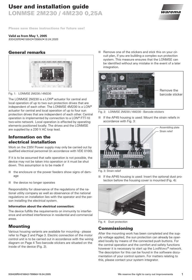
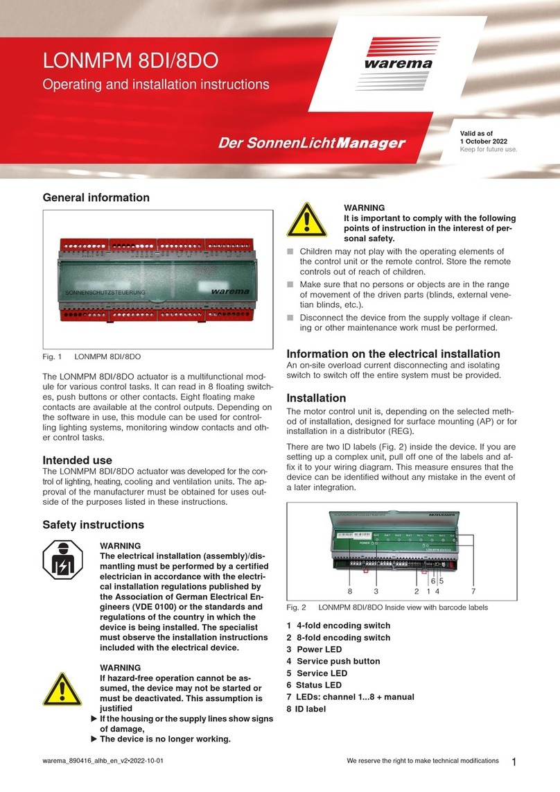
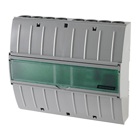
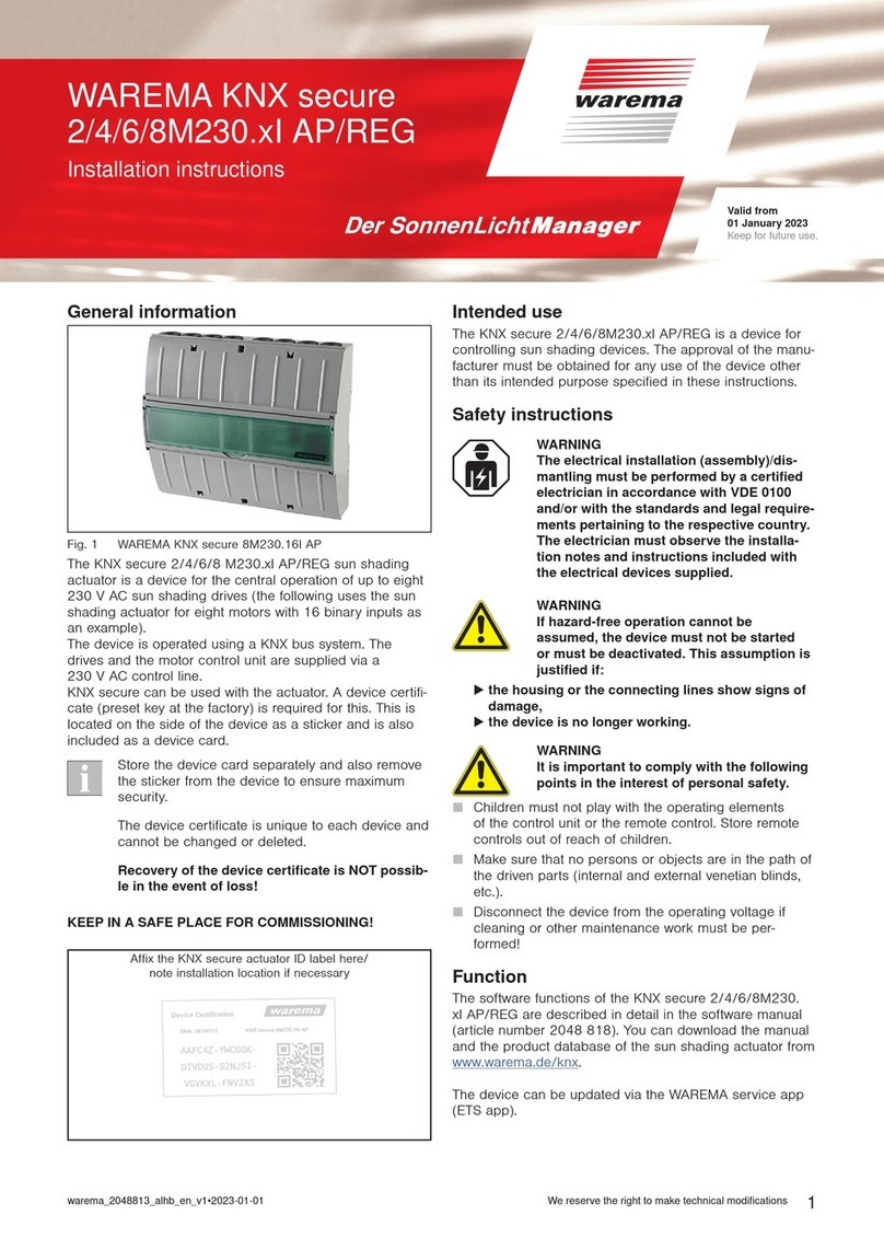
  9. WAREMA KNX MSE 6M230 Series User manual

WAREMA KNX MSE 6M230 Series User manual

Operating and installation instructions
KNXMSE 6M230
Keep for future use.
Valid from 01 November 2015
816859_d•en•2015-11-01 We reserve the right to carry out improvements 1
Safety instructions
WARNING
The electrical installation must be per-
formed by a certified electrician in accord-
ance with the electrical installation regu-
lations published by the Association of
German Electrical Engineers (VDE0100)
or the standards and regulations of the
country in which the device is being in-
stalled. The specialist must observe the
installation instructions included with the
electrical device.
WARNING
If hazard-free operation cannot be as-
sumed, the device may not be started or
must be deactivated. This assumption is
justified
 if the housing or the supply lines show
signs of damage,
 the device is no longer working.
WARNING
It is important to comply with the follow-
ing instructions in the interest of personal
safety!
Children may not play with the operating elements of
the control unit or the remote control. Store the remote
controls out of range of children.
Make sure that no persons or objects are in the range
of movement of the driven parts (blinds, external vene-
tian blinds, etc.).
Disconnect the device from the supply voltage if clean-
ing or other maintenance work must be performed.
Function of the motor control unit
Convenience and safety functions
These functions are integrated in the software. A detailed
description can be found in the KNXMSE6M230 manual.
The motor control unit manual and product database can
be downloaded from www.warema.de.
General
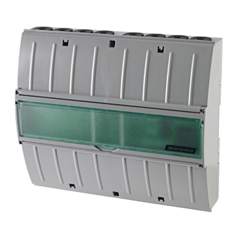
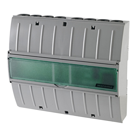
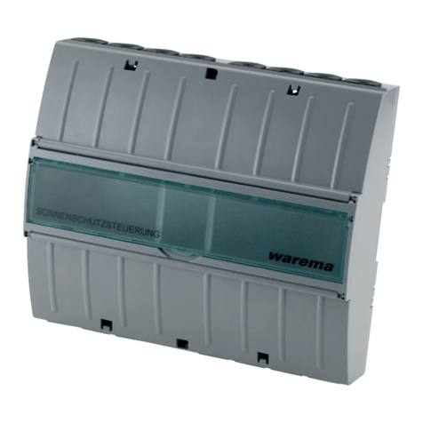
Fig. 1 KNXMSE6M230
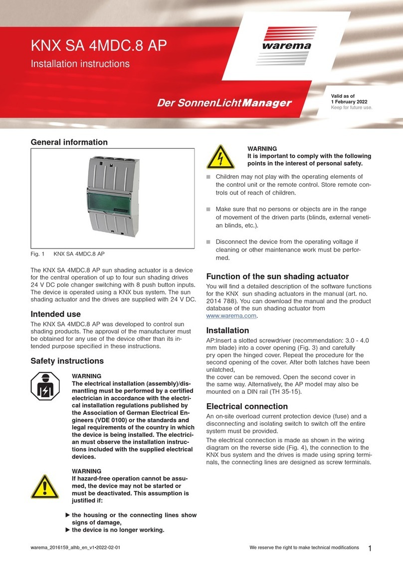
The motor control unit (MSE) KNXMSE6M230 is an
KNXactuator for the centralized and local control of up to
six output channels. Four of these channels can be used
for the mutually independent control of the sun shading
drives. Two additional channels can be used for the mutu-
ally independent control of one or two sun shading drives
or two or four lamps.
Central operation takes place via an KNX bus system; for
local operation, operating elements (sunblind push button,
light switch) can be connected to the device, or the KNX
bus system can be used. The drive and MSE are supplied
via a 230VAC line. The sun shading drives and the light-
ing systems can also have a separate power supply.
Intended use
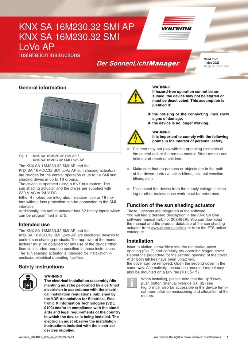
This device was developed to control sun shading and
lighting systems. The approval of the manufacturer must
be obtained for uses outside of the purposes listed in
these instructions.
816859_d•en•2015-11-01We reserve the right to carry out improvements
2
Installation
The motor control unit is, depending on the selected
method of installation, designed for surface mounting (AP)
or for installation in a distributor (REG).
 Surface-mounted housing (AP)
Insert a slotted screwdriver (recommendation:
3.0 - 4.0mm blade) into the respective cover opening
(see Fig. 4) and carefully pry the folding cover open.
Repeat the procedure for the second opening of the
cover. The cover can be folded up when both catches
have been released. The second cover can be opened
in the same manner. Alternatively, the surface-mounted
variant can also be mounted on a DIN rail (TH 35-15
as per EN 60715: 2001).
 DIN rail-mounted housing (REG)
When installing the device in a distributor, clip it onto a
symmetrical DIN rail (TH35as per EN 60715: 2001).
To ease connecting the device, the terminal covers can
be removed (see Fig. 2). One of the terminal covers
can be removed to connect the network.
Remove the terminal covers:
Insert a suitable screwdriver
into the notch.
Fig. 2 Removing the terminal covers (REG variant)
Electrical installation
An on-site overload current protection device (fuse) and a
disconnecting and isolating switch to switch off the entire
system must be provided.
The motor control unit is electrically connected according to
the wiring diagram on the back of this page (see Fig. 6 and
Fig. 7).
Commissioning
After installation has been completed and the supply volt-
age has been connected, the device can be operated via
the optionally available manual control panel MABE12.
In the REG and the FT variant, operation is also possible
using a membrane keyboard (Fig. 3).
Local operation
The membrane keyboard of the REG and the FT variant
consists of 12 buttons, each with an integrated LED:
1
A1.1 A2.1
A1.2 A2.2
23456
Fig. 3 Membrane keyboard
Upon delivery, all outputs can be operated in dead man's
mode (jog mode, when the button is released, the re-
spective relay drops out immediately). When a button is
pressed, the respective LED lights up. Immediately thereaf-
ter, the relay begins operating and the associated output is
switched accordingly. Outputs A1.1 and A1.2 and outputs
A1.2 and A2.2 are locked in the software (safety feature).
This can be changed by adjusting the configuration later.
The HIGH and LOW outputs of channels 3 to 6 are inter-
locked electrically.
WARNING
Never randomly press the keys on the
membrane keyboard without having a line
of sight to the sun shading system. When
you work with the manual control panel,
you will not receive visual feedback about
the state of the relay because there are no
LEDs integrated in the control panel.
Programming
 Press the programming button (Fig. 7) to put the
device into programming mode. The red LED lights
up when programming mode is active. The device is
programmed on a PC with the corresponding software.
This software ends the programming mode automati-
cally. The red LED goes out.
 If the programming mode is to be ended earlier, press
the programming button again. The red LED goes out.
NOTE: Take suitable precautions to prevent damage
due to electrostatic discharge!
Maintenance
There are no parts within the device that require mainte-
nance. In the event of a malfunction, the built-in miniature
fuses should only be changed by a certified electrician.
Liability
In the event of the failure to comply with the product infor-
mation contained in these instructions, or if the device is
used in any manner other than its designated or intended
use, the manufacturer may refuse to honour warranty
claims for product damage. In this case, liability for con-
sequential harm to persons or damage to property will
also be excluded. Follow the instructions in the operating
manual of your sun shading system. Liability cannot be
accepted for damage to the sun shading system resulting
from operation while iced over.
Disposal
After its use, the device must be disposed of according to
legal regulations or returned to your local recycling centre.
KNX is a registered trademark of the KNXAssociation.
3
816859_d•en•2015-11-01 We reserve the right to carry out improvements
Technical data
KNXMSE6M230 Min. Typ. Max. Unit
Operating voltage 198 230 253 V AC
Quiescent current con-
sumption, primary 13 18 25 mA
Temperature fuse, primary 131 135 °C
Drive output
Switching capacity at
230VAC / cosφ = 0.6 500 VA
Light outputs (total power of outputs A1.1...A1.4)
230V AC halogen lamps* 2000* W
230V AC bulbs* 2000* W
Fluorescent tubes 163 μF 1500* VA
*Total power of all 4 outputs. If lamps are controlled, the minia-
ture fuse F1 / 6.3 AT H can be replaced by a 10 AT H fuse.
**Max. 500W per channel
KNX input TP 1
KNX current consumption 9 mA
Voltage 29 V DC
Inputs for local operating elements (sunblind push button,
light switch, light push button/push button, 1-pin)
Local voltage active 8 24 36 V DC
Local voltage inactive -0.5 0 1.5 V DC
Housing
Dimensions see Fig. 4, Fig. 5
Degree of protection IP30
Degree of protection
(PE is looped through) I
Miscellaneous
Automatic operation Type 1
Software class A
Location of use Clean ambient conditions
Konformität
available at
www.warema.com
The device meets the EMC guidelines for use in residential and
commercial areas.
Ambient conditions
Operating temperature 0 20 40 °C
Storage temperature 0 20 60 °C
Humidity
(not condensing) 10 40 85 %RH
Connection
Supply line, outputs,
push buttons
Screwed terminals
KNX bus system Connectors
Terminals
Supply line, outputs,
push buttons
0.5 ... 2.5 mm
KNX bus system 0.6 ... 0.8 mm ∅
Article numbers
KNXMSE6M230 REG 1002 632
KNXMSE6M230 AP 1002 719
KNXMSE6M230 AP
(variant: FT) 2013 519
Manual control panel
MABE12 1002 631
WAREMA Renkhoff SE
Hans-Wilhelm-Renkhoff-Strasse 2
D-97828 Marktheidenfeld
Germany
210 mm
119 mm
184 mm
180 mm
60 mm
3 ‒ 4 mm
Fig. 4 Dimensions of surface-mounted housing (AP), 12 MW
60 mm
95 mm
90 mm
210 mm / 12 MW
60 mm
Fig. 5 Dimensions of rail-mounted housing (REG), 12 MW
816859_d•en•2015-11-01We reserve the right to carry out improvements
4
PE PE PE PE NNLL
X1
98765432198
A
1.1
A
1.2
A
2.1
A
2.2
E
3.2
E
3.1
7654321
123456789123456789
987654321987654321
X5X11
N
All motor lines
H05RR-F 4 G 0.75 bk
Type WAREMA
132
F1
6,3 AT H
To next
components
Plug-and-socket
connection
KNX MSE
6M230
M1 M2 M3 M4 M5 M6
1
PE PEN
gnyl brbl
132
MM
1
bl
------------------ Network 2 --------------------------------- Network 1 --------------
X2
Output 3 --------- Output 4 -------- - Output 5 Output 6
Status-
LED
Prog-
LED
Programming-
button
X6
LL
11 32 23
M
1
M
1
NNNN
brbl
X3
PE PE
11 32 23
M
1
M
1
PE PEN
brbl
X4
N
F2
6,3 AT H
F3
6,3 AT H
P
E
2.2
P
E
2.1
E
1.2
E
1.1 PE
6.2
E
6.1 P
E
5.2
P
E
5.1
E
4.2
E
4.1PX7
++--
KNXKNX
Output to next
Component
Input from previous component
PYCYM 2x2x0,8mm ø
Max. cable length
50m
E
3.2
E
3.1
123456789X5
P
21
P
0
All push button lines
JY(St)Y 2x2x0,8 mm ø
connection example:
Sunshade push button
N
L
PE
N
L
PE
Operating element
see
manual!
415263
St1
Connector
for manual control
panel, 12 inputs
(MABE 12)
Attention: Only one motor may be
connected per motor terminal set.
Parallel connection will damage
the motor!
Power line provided
by customer
230 V AC / 50 Hz / 16 A
3x1,5 mm
2
Max. total current
per 15 A
bk gnyl br bk bl br bk gnyl gnyl bk brbl bk gnyl gnyl bk
Fig. 6 KNXMSE6M230 / 6 drives
PE PE PE PE NNLL
X1
987654321 98
A
1.1
A
1.2
A
2.1
A
2.2
E
3.2
E
3.1
7654321
123456789 123456789
987654321 987654321
X5
N
All motor lines
H05RR-F 4 G 0.75 bk
Type WAREMA
F1*
6,3 AT H
To next
components
Plug- and socket
connection
KNX MSE
6M230
M1 M2 M3 M4
PE PEN
------------------ Network 2 ----------------------------------- Network 1 ----------------
X2
Status-
LED
Programming-
button
X6
LL
11 32 23
M
1
M
1
NNNN
X3
PE PE
11 32 23
M
1
M
1
PE PEN
brbl
X4
N
F2
6,3 AT H
F3
6,3 AT H
P
E
2.2
P
E
2.1
E
1.2
E
1.1PE
6.2
E
6.1P
E
5.2
P
E
5.1
E
4.2
E
4.1PX7
KNXKNX
Output to next
component
Input from previous
component
PYCYM 2x2x0,8 mm ø
Attention: Only one motor may be
connected per motor terminal set.
Parallel connection will damage the motor!
Max. cable length
50m
123456789 X5
E
2.2
P
E
2.1
E
1.2
E
1.1P
1
P
All push button lines
JY(St)Y 2x2x0,8 mm ø
Supply line (drives) provided
by customer
230 V AC / 50 Hz / 16 A
3x1,5 mm²
Max. total current per supply 15 A
Supply line (lights) provided
by customer
230 V AC / 50 Hz / 16 A
3x1,5 mm²
Max. total current per supply 15 A
Attention: All power circuits must be deactivated
during maeintenance work.
NOTE: The PE terminals of terminal strips X1 and
X2 are not connected to each other. The PE
terminals of terminal strips X2, X3 and X4 are
connected to each other.
Connection example
Light push button
*When controlling lights,
a fuse of max. 10 AT H
may be used.
N
L1
PE
N
L1
PE
N
L2
PE
N
L2
PE
Operating element
12 3456
Max. cable length
50m
E
3.2
E
3.1
123456789
X5
P
21
P
0
All push button lines
JY(St)Y 2x2x0,8 mm ø
Connection example
Sunshade push button
St1
++--
Connector
for manual control-
panel 12 inputs
(MABE12)
See
manual
!
X11
Output 3 ---------Output 4 ------------ Output 5 Output 6
Prog-
LED
bl br bk gnyl gnyl bl br bk bl br bk gnyl gnyl bk
Fig. 7 KNXMSE6M230 / 4 drives and 4 lamps

This manual suits for next models

6

Other WAREMA Controllers manuals

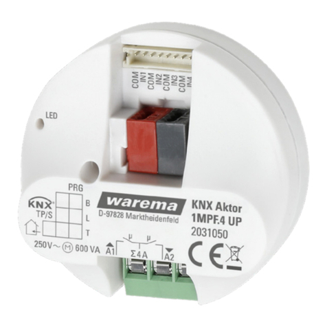
WAREMA 1MPF.4 UP User manual

WAREMA

WAREMA 1MPF.4 UP User manual

WAREMA 4M230.12 2Down REG User manual

WAREMA

WAREMA 4M230.12 2Down REG User manual

WAREMA KNX SA 16M230 SMI REG User manual

WAREMA

WAREMA KNX SA 16M230 SMI REG User manual

WAREMA KNX 2024236 User manual

WAREMA

WAREMA KNX 2024236 User manual

WAREMA BACnet 4M230.8I AP User manual

WAREMA

WAREMA BACnet 4M230.8I AP User manual

WAREMA KNX SA 4MDC.8 AP User manual

WAREMA

WAREMA KNX SA 4MDC.8 AP User manual

WAREMA WMS SA 1 UP User manual

WAREMA

WAREMA WMS SA 1 UP User manual

WAREMA Omnexo 2M230 REG User manual

WAREMA

WAREMA Omnexo 2M230 REG User manual

WAREMA LONMPM 8DI User manual

WAREMA

WAREMA LONMPM 8DI User manual

WAREMA KNX SA 2M230 REG User manual

WAREMA

WAREMA KNX SA 2M230 REG User manual

WAREMA LONMSE 6M230 User manual

WAREMA

WAREMA LONMSE 6M230 User manual

WAREMA LONMSE 2M230I Manual

WAREMA

WAREMA LONMSE 2M230I Manual

WAREMA KNX secure Series User manual

WAREMA

WAREMA KNX secure Series User manual

WAREMA KNX SA 16M230.32 SMI AP User manual

WAREMA

WAREMA KNX SA 16M230.32 SMI AP User manual

WAREMA KNX SA 2M230 REG User manual

WAREMA

WAREMA KNX SA 2M230 REG User manual

WAREMA Omnexo 2M230 AP User manual

WAREMA

WAREMA Omnexo 2M230 AP User manual

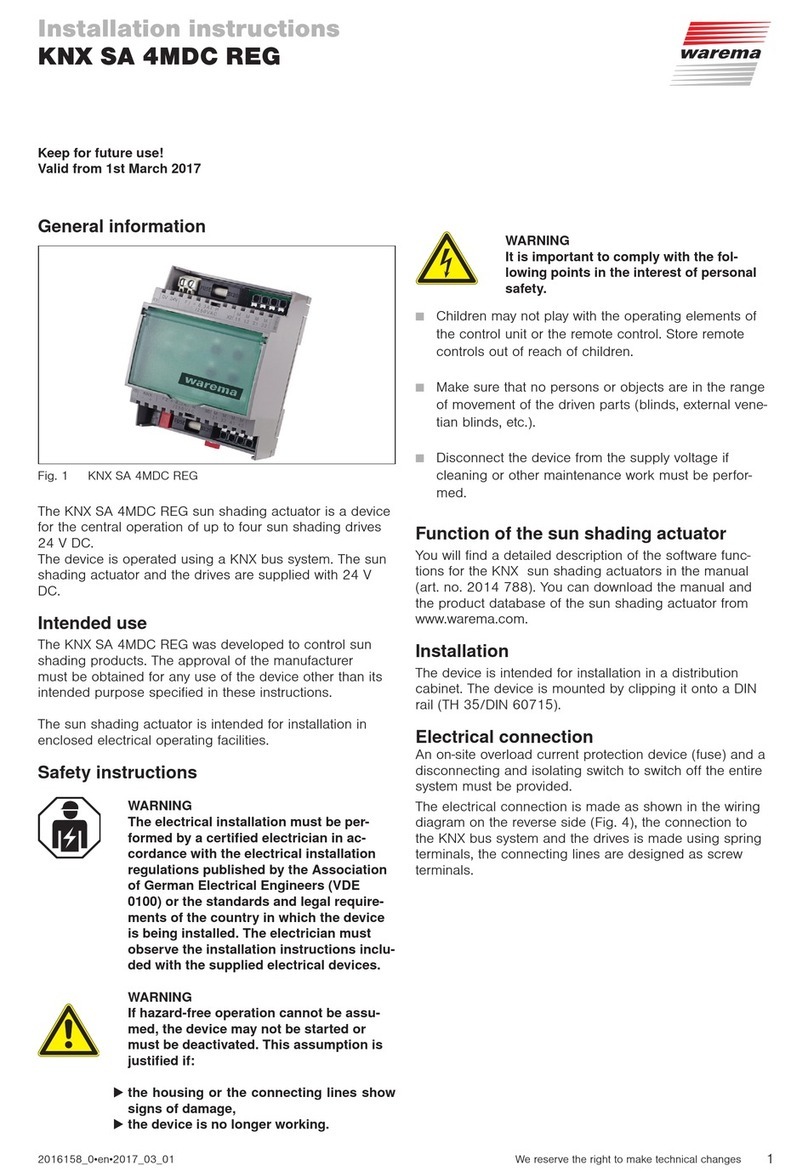
WAREMA KNX SA 4MDC REG User manual

WAREMA

WAREMA KNX SA 4MDC REG User manual

WAREMA KNX SA 4MDC.8 AP User manual

WAREMA

WAREMA KNX SA 4MDC.8 AP User manual

WAREMA KNX SA Series User manual

WAREMA

WAREMA KNX SA Series User manual

WAREMA KNX SA 2M230 AP Series User manual

WAREMA

WAREMA KNX SA 2M230 AP Series User manual

WAREMA Omnexo 1M230 UP User manual

WAREMA

WAREMA Omnexo 1M230 UP User manual

WAREMA LONMSE 2M230 Manual

WAREMA

WAREMA LONMSE 2M230 Manual

WAREMA KNX secure Series User manual

WAREMA

WAREMA KNX secure Series User manual

WAREMA KNX SA 16M230.32 SMI AP User manual

WAREMA

WAREMA KNX SA 16M230.32 SMI AP User manual

Popular Controllers manuals by other brands

Vemer HT NiPt Series user manual

Vemer

Vemer HT NiPt Series user manual

Edimax AC-M1000 user manual

Edimax

Edimax AC-M1000 user manual

Wallbox Commander 2 installation guide

Wallbox

Wallbox Commander 2 installation guide

Link SC360 installation guide

Link

Link SC360 installation guide

Swagelok RHPS Series user manual

Swagelok

Swagelok RHPS Series user manual

Curtis 1268 installation instructions

Curtis

Curtis 1268 installation instructions

vissonic VIS-CATC-A user manual

vissonic

vissonic VIS-CATC-A user manual

Emerson EC3-X32 Operating	 instruction

Emerson

Emerson EC3-X32 Operating instruction

Friendess FSCUT4000 user manual

Friendess

Friendess FSCUT4000 user manual

TELECO AUTOMATION TVRGBD000ST24 quick start guide

TELECO AUTOMATION

TELECO AUTOMATION TVRGBD000ST24 quick start guide

ESBE CR Series manual

ESBE

ESBE CR Series manual

Geco G-406-P09 user manual

Geco

Geco G-406-P09 user manual

Johnson Controls EDA-8102 Installation sheet

Johnson Controls

Johnson Controls EDA-8102 Installation sheet

Simex PUR-49D user manual

Simex

Simex PUR-49D user manual

Sciener BLE4.1 user manual

Sciener

Sciener BLE4.1 user manual

Airstream TC5-ITA user manual

Airstream

Airstream TC5-ITA user manual

Sunnen HTA-2000 (2M) manual

Sunnen

Sunnen HTA-2000 (2M) manual

MLSC C-80 Operator's manual

MLSC

MLSC C-80 Operator's manual

manuals.online logo
manuals.online logoBrands
  • About & Mission
  • Contact us
  • Privacy Policy
  • Terms and Conditions

Copyright 2025 Manuals.Online. All Rights Reserved.