manuals.online logo
Brands
  1. Home
  2. •
  3. Brands
  4. •
  5. WAREMA
  6. •
  7. Controllers
  8. •
  9. WAREMA KNX 2024236 User manual

WAREMA KNX 2024236 User manual

1
warema_2030680_alhb_en_v2•2022-04-01 We reserve the right to make technical modifications
The device is configured via the KNX software ETS. The
product database required for this (.knxprod) can be
found in the online catalogue of the ETS or on the internet
at http://www.warema.de/knx.
Scope of delivery
Housing with display
Support plate
Connecting line for analogue/digital inputs
Additionally required (not included in the scope of deliv-
ery):
Switch box ∅60 mm, 42mm deep
Frame (for use 55 x 55mm), suitable for the switch
program used in the building
Technical data (shortened)
Installation Flush-mounted (wall mounting in
switch box
∅60mm, 42mm deep)
Degree of protection IP 20
Dimensions approx. 55 x 55 x 35 mm
(W x H x D), structure depth
approx. 7mm
Total weight approx. 90 g (incl. connecting
line, support plate)
Ambient temperature Operation -20...+70°C,
Bearing -30...+70°C
Surrounding air humidity max. 95% RH, avoid condensation
Operating voltage KNX bus voltage
Bus current max. 18mA
Data output KNX +/- bus plug terminal
Inputs 4x analogue/digital,
max. line length 10m
Temperature measuring
range
-20...+70°C
Article number 2024236
Optional accessories
Cover frame
GIRA E2 pure white,
glossy
2004335
The product conforms with the regulations of the EU
directives.
Cleaning
Clean the housing with a soft, dry cloth. Do not use deter-
gents, cleaning agents, solvents, abrasive substances or
steam cleaners!
General information
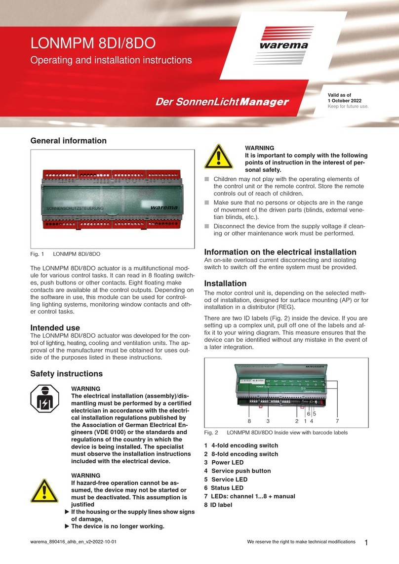
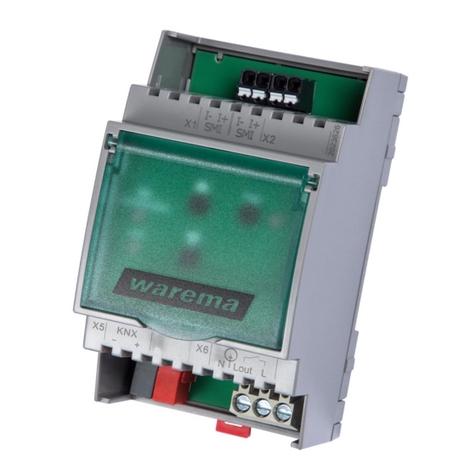
Fig. 1 WAREMA KNX room controller
The WAREMA KNX Room Controller for the KNX bus
system measures room temperature. It has a Touch
Display on which different display and operation sides are
displayed depending on the individual configuration. The
device is supplemented with a frame from the switch se-
ries used in the building so that it blends seamlessly into
the interior fittings.
Functions:
Colour Touch Display with display and operation sides
for
1x current temperature display
1x bus data display (4 universal display places)
1x temperature regulation (including mode switching)
3x drive operations (shading, window) with button
and/or slide controls
3x light switches or dimmers (with percentage dis-
play)
1x RGB light control
1x light-colour temperature settings
1x HCL controls (light-colour temperature adjustment
over various adjustable periods of time)
1x scene (4 scenes with retrieval and saving)
Week time switch
2x information pages for every two 14 byte text
objects
Device settings
4 inputs for binary contacts or temperature sensor
Adjustable limit value
8 AND and 8 OR logic gates
8 multifunction modules (calculator)
4 adjusting variable comparators
Measuring the temperature, mixed value calculation.
PI controller for heating and cooling with
fan coil controls
Summer compensation for cooling
Valid as of
1 April 2022
Keep for future use.
WAREMA KNX
room controller
Short description
warema_2030680_alhb_en_v2•2022-04-01We reserve the right to make technical modifications
2
Installation, commissioning
Information for installation
ARNINGW
Only certified electricians (according to
VDE0100) may install, assamble/(disman-
tle) examine, commission and troubleshoot
the device.
AUTIONC
Electrical voltage!
There are unprotected live components
inside the device.
Comply with the VDE regulations.
Connect all lines in a de-energised state
and meet guidelines against accidental
switch-on.
Do not commission the device if it is dam-
aged.
Deactivate the device or unit and secure
against accidental switch-on if a guaran-
tee of hazard-free operation cannot be
assumed.
The device is intended for proper use only. All warranties
expire if the device is subjected to any improper adjust-
ment or use that does not comply with the operating
instructions.
The device must be inspected for potential mechanical
damage immediately after being unpacked. If damage has
taken place during transport, the supplier must be notified
of this immediately.
The device may only be used as a fixed installation, i.e.
only when fully assembled and after all installation and
commissioning procedures are completed
and only in the intended environment.
WAREMA RENKHOFFSE is not liable for any changes to
the norms and standards after publication of the operating
instructions.
Installation location
The sensor is installed under plaster in a switch box
(60mm, 42mm deep).
The sensor may only be installed and operated in
dry indoor rooms.
Avoid condensation.
 Please ensure when selecting the installation location
that the measured values are remain as unaffected by
external influences as possible.
Possible sources of interference are:
Direct sunlight
Draft from windows or doors
Draft from pipes that run from other rooms into the box
in which the sensor is installed
Warming or cooling of the structure upon which the
sensor is installed,
e.g. by solar radiation, heating pipes or cold water
pipes
Connecting lines that run from a colder or warmer area
to the sensor
Deviations in temperature due to such sources of interfer-
ence can be corrected in the ETS in order to achieve the
indicated accuracy of the sensor (temperature offset).
Device structure
5
1
2
7
6
4
3
Fig. 2 View with frame and support plate
1 Frame (not included in the
scope of delivery)
4 PRG button (recessed)
2 Support plate 5 PRG LED (recessed)
3 Connecting line socket
inputs
6 Catches
7 KNX bus terminal +/-
Assigning connecting lines inputs:
Input 1: white / black (GND)
Input 2: yellow / black (GND)
Input 3: purple / black (GND)
Input 4: blue / black (GND)
Installing the sensor
Install the wind-proof box with the connecting line first.
Insulate the supply tube to avoid drafts.
Screw the support plate onto the box and apply the switch
program cover. Connect the bus line +/- to the black and
red KNX plug connector and plug the KNX plug connector
into the correct socket (no. 7). Connect the analogue/digi-
tal inputs via the included cable whip (no. 3) if required.
Mount the housing securely onto the metal frame with the
catches so that the housing and frame are fixed.
Information for installation and commissioning
Never expose the device to water (rain) or dust. This can
damage the electronics. A relative humidity cannot exceed
95%. Avoid condensation.
After the bus voltage is applied, the device performs an
initialising phase of a few seconds. No information can be
received or sent by the bus during this time.
Obligations for the disposal of electrical
devices
A marking with this symbol indicates the following
obligations under the scope of legal regulations:

 The owner of this electrical device must dispose of it
separately from unsorted municipal waste for further
recycling.
 Used batteries and accumulators that are not enclosed
in the old device, as well as lamps/bulbs that can be
removed from the old device without breaking, must be
disposed of separately.
 Distributors of electrical devices and disposal compa-
nies are obliged to take back the equipment free of
charge.
 The owner must take it upon themselves to delete any
personal data contained in the electrical device prior to
disposal.
Other WAREMA Controllers manuals

WAREMA KNX SA 4MDC.8 AP User manual

WAREMA

WAREMA KNX SA 4MDC.8 AP User manual

WAREMA KNX SA 16M230.32 SMI AP User manual

WAREMA

WAREMA KNX SA 16M230.32 SMI AP User manual

WAREMA KNX secure Series User manual

WAREMA

WAREMA KNX secure Series User manual

WAREMA Omnexo 1M230 UP User manual

WAREMA

WAREMA Omnexo 1M230 UP User manual

WAREMA Omnexo 2M230 AP User manual

WAREMA

WAREMA Omnexo 2M230 AP User manual

WAREMA LONMSE 2M230I Manual

WAREMA

WAREMA LONMSE 2M230I Manual

WAREMA LONMPM 8DI User manual

WAREMA

WAREMA LONMPM 8DI User manual

WAREMA KNX SA 4MDC REG User manual

WAREMA

WAREMA KNX SA 4MDC REG User manual

WAREMA Omnexo 2M230 REG User manual

WAREMA

WAREMA Omnexo 2M230 REG User manual

WAREMA KNX SA 2M230 AP Series User manual

WAREMA

WAREMA KNX SA 2M230 AP Series User manual

WAREMA KNX SA 4MDC.8 AP User manual

WAREMA

WAREMA KNX SA 4MDC.8 AP User manual

WAREMA BACnet 4M230.8I AP User manual

WAREMA

WAREMA BACnet 4M230.8I AP User manual

WAREMA KNX secure Series User manual

WAREMA

WAREMA KNX secure Series User manual

WAREMA KNX SA 16M230.32 SMI AP User manual

WAREMA

WAREMA KNX SA 16M230.32 SMI AP User manual

WAREMA LONMSE 2M230 Manual

WAREMA

WAREMA LONMSE 2M230 Manual

WAREMA KNX SA Series User manual

WAREMA

WAREMA KNX SA Series User manual

WAREMA WMS SA 1 UP User manual

WAREMA

WAREMA WMS SA 1 UP User manual

WAREMA KNX SA 2M230 REG User manual

WAREMA

WAREMA KNX SA 2M230 REG User manual

WAREMA LONMSE 6M230 User manual

WAREMA

WAREMA LONMSE 6M230 User manual

WAREMA KNX SA 16M230 SMI REG User manual

WAREMA

WAREMA KNX SA 16M230 SMI REG User manual

WAREMA KNX SA 2M230 REG User manual

WAREMA

WAREMA KNX SA 2M230 REG User manual

WAREMA KNX MSE 6M230 Series User manual

WAREMA

WAREMA KNX MSE 6M230 Series User manual

WAREMA 1MPF.4 UP User manual

WAREMA

WAREMA 1MPF.4 UP User manual

WAREMA 4M230.12 2Down REG User manual

WAREMA

WAREMA 4M230.12 2Down REG User manual

Popular Controllers manuals by other brands

NAiS FP1 Hardware

NAiS

NAiS FP1 Hardware

Reporter GX1122-DGR/H user manual

Reporter

Reporter GX1122-DGR/H user manual

Well AVR-REL-GUARD1000-WL user manual

Well

Well AVR-REL-GUARD1000-WL user manual

Altronix AL400ULACM installation guide

Altronix

Altronix AL400ULACM installation guide

Xylem LOWARA FF128DP Series Installation, operation and maintenance manual

Xylem

Xylem LOWARA FF128DP Series Installation, operation and maintenance manual

Siemens RAJA+ Installation, operation & maintenance instructions

Siemens

Siemens RAJA+ Installation, operation & maintenance instructions

ITRON RB 4000 instruction manual

ITRON

ITRON RB 4000 instruction manual

Halma ALICAT SCIENTIFIC PC quick start guide

Halma

Halma ALICAT SCIENTIFIC PC quick start guide

Harbortronics DigiSnap 3000 user manual

Harbortronics

Harbortronics DigiSnap 3000 user manual

Redback A 4565B operating manual

Redback

Redback A 4565B operating manual

Makeblock Airblock Operation guide

Makeblock

Makeblock Airblock Operation guide

Future light CP-256 MST user manual

Future light

Future light CP-256 MST user manual

Emerson EL-O-Matic F-Series Safety guide

Emerson

Emerson EL-O-Matic F-Series Safety guide

Kershaw Systems A-WEB Host Tech Guide

Kershaw Systems

Kershaw Systems A-WEB Host Tech Guide

JUMO diraTRON 104 Brief instructions

JUMO

JUMO diraTRON 104 Brief instructions

Samson 3371 Series Mounting and operating instructions

Samson

Samson 3371 Series Mounting and operating instructions

BEKA BA458C manual

BEKA

BEKA BA458C manual

Balmar MAX CHARGE MC-614 quick start guide

Balmar

Balmar MAX CHARGE MC-614 quick start guide

manuals.online logo
manuals.online logoBrands
  • About & Mission
  • Contact us
  • Privacy Policy
  • Terms and Conditions

Copyright 2025 Manuals.Online. All Rights Reserved.