manuals.online logo
Brands
  1. Home
  2. •
  3. Brands
  4. •
  5. WAREMA
  6. •
  7. Controllers
  8. •
  9. WAREMA LONMSE 2M230I Manual

WAREMA LONMSE 2M230I Manual

User and installation guide
LONMSE 2M230I / 4M230I 0,25A
Please save these instructions for future use!
Valid as from May 1, 2005
930426S0•816857•7995k0•18.04.2005
930426S0•816857•7995k0•18.04.2005 We reserve the right to carry out improvements 1
General remarks
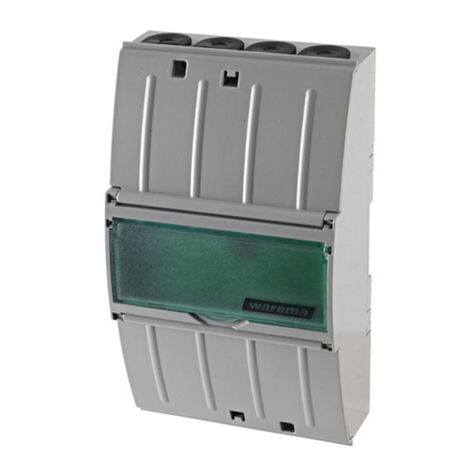
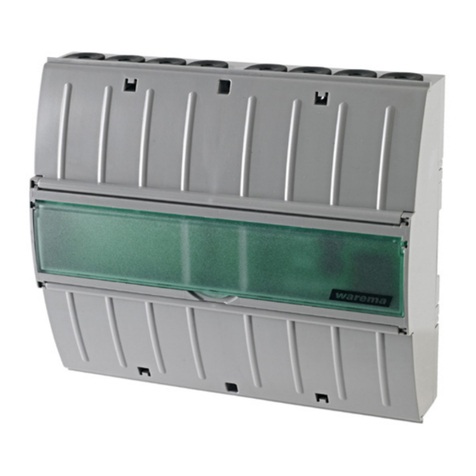
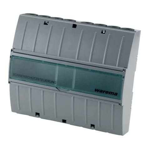
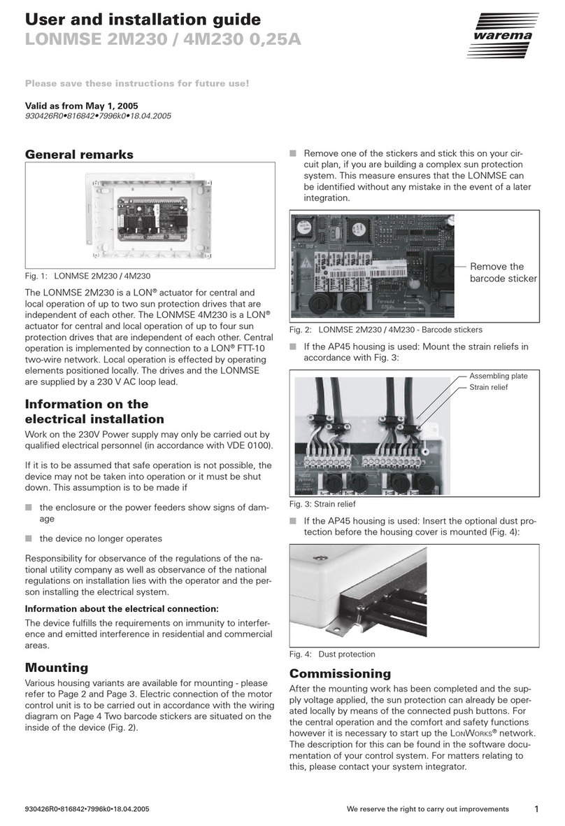
Fig. 1: LONMSE 2M230I / 4M230I
The LONMSE 2M230I is a LON®actuator for central and
local operation of up to two sun protection drives that are
independent of each other. The LONMSE 4M230I is a LON®
actuator for central and local operation of up to four sun
protection drives that are independent of each other. One
incremental sensor input per motor output is available for
exact detection and control of the sun blind position. The
LONMSE 2M230I furthermore disposes of two signaling
contact inputs. Central operation is implemented by connec-
tion to a LON®FTT-10 two-wire network. Local operation is
effected by operating elements positioned locally. The drives
and the LONMSE are supplied by a 230 V AC loop lead.
Information on the
electrical installation
Work on the 230V Power supply may only be carried out by
qualified electrical personnel (in accordance with VDE 0100).
If it is to be assumed that safe operation is not possible, the
device may not be taken into operation or it must be shut
down. This assumption is to be made if
■the enclosure or the power feeders show signs of dam-
age
■the device no longer operates
Responsibility for observance of the regulations of the na-
tional utility company as well as observance of the national
regulations on installation lies with the operator and the per-
son installing the electrical system.
Information about the electrical connection:
The device fulfills the requirements on immunity to interfer-
ence and emitted interference in residential and commercial
areas.
Mounting
Various housing variants are available for mounting - please
refer to Page 2 and Page 3. Electric connection of the motor
control unit is to be carried out in accordance with the wiring
diagram on Page 4. Two barcode stickers are situated on the
inside of the device (Fig. 2).
■ Remove one of the stickers and stick this on your cir-
cuit plan, if you are building a complex sun protection
system. This measure ensures that the LONMSE can
be identified without any mistake in the event of a later
integration.
Remove the
barcode sticker
Fig. 2: LONMSE 2M230I / 4M230I - Barcode stickers
■ If the AP45 housing is used: Mount the strain reliefs in
accordance with Fig. 3:
Assembling plate
Strain relief
Fig. 3: Strain relief
■ If the AP45 housing is used: Insert the optional dust pro-
tection before the housing cover is mounted (Fig. 4):
Fig. 4: Dust protection
Commissioning
After the mounting work has been completed and the sup-
ply voltage applied, the sun protection can already be oper-
ated locally by means of the connected push buttons. For
the central operation and the comfort and safety functions
however it is necessary to start up the LONWORKS®network.
The description for this can be found in the software docu-
mentation of your control system. For matters relating to
this, please contact your system integrator.
930426S0•816857•7995k0•18.04.2005We reserve the right to carry out improvements
2
Status LED’s and service key: On the circuit board of the
LONMSE you will find a red and a green status LED as well
as a service key (see fig. 5). Carry out a simple function test:
After switching on the supply voltage or after a quick press
on the service key the green LED lights up for approx. 0.5
seconds and then goes out. A continuous lighting up indi-
cates a fault in the device. In this case, contact your system
integrator. The red LED then lights up for a duration of up to
20 seconds after the switching on of the supply voltage. As
soon as the device is ready for operation this LED begins to
flicker irregularly. A continuous light indicates a fault in the
device. Also contact your system integrator in this case.
Note: Take suitable precautions in order to avoid damage
through electrostatic discharges!
Network terminals
Service-key
Satus-LEDs
Fig. 5: LONMSE 2M230I / 4M230I
Function of the LONMSE
Comfort and safety functions
These functions have been integrated in your software and
adapted exactly to your wishes. A detailed description is
contained in the software documentation of your sun pro-
tection control unit.
Local operation
■Brief operation of the sun blind push button (< 0.6 sec-
onds) is used to set the sun blind in small steps.
■If the push button is pressed for between 0.6 and 2.6
seconds, a move command is triggered and the sun
blind moves for about as long as the button is pressed.
■If the push button is pressed for longer than 2.6 sec-
onds, the sun blind moves to the upper or lower end
position. In order to stop the movement, press the but-
ton of the opposite direction of movement briefly.
Maintenance
There are no parts to be maintained within the device. In
case of a malfunction the installed miniature fuses may only
be replaced by qualified electrical personnel. Note: The de-
vice has a thermal fuse which interrupts the power supply
when the operating temperature rises too high. After the
thermal fuse has been triggered, the device is unusable and
has to be sent in to the manufacturer to be repaired. Over-
heating of the device indicates a fault. Therefore switch off
the plant and check the correct installation.
Liability
The manufacturer can reject the warranty for damage to the
product if the product information given in these instructions
is not observed, if it is used for purposes other than those
specified or if used improperly. Liability for consequent dam-
age to persons or property is also excluded in this case. Ob-
serve the specifications in the operating instructions of your
sun blind. Liability for damage to the sun blind caused by
operation during icing or icy conditions is also excluded.
Technical data
LONMSE
2M230I/4M230I 0,25A min typ max unit
Supply 230 V AC
Operating voltage 207 230 253 V AC
Primary zero-signal cur-
rent 20 25 mA
Thermal-fuse (primary) 131 135 °C
Safety class I
Output (drive)
Operating voltage via re-
lais 230 V AC
Operating current 0,1 1 2,15 A
Switching capacity at
230 V AC/cos ϕ=0,2 460 VA
Current monitoring 0,25 A
Miniature fuse per drive 3,15 AT
Inputs incremental encoder
Control voltage active 10 12 30 V DC
Control voltage inactive 0 0 1 V DC
Operating frequency 80 100 120 Hz
Power supply for incre-
mental encoders, total
current max. 15 mA
10 16 26 V DC
Input LON®FTT-10
Inputs on local operating elements, (sun blind but-
tons, 1-pin) and signaling contact inputs
Local voltage active 8 24 36 V DC
Local voltage inactive -0,5 0 3 V DC
Housing variants Degree of protection
Dimensions see fig. 6,
7, 8 and 9.
AP45-housing with dust
protection IP10
AP45-Clip housing IP10
Clip housing for distribu-
tion cabinet IP20
AP60 housing IP31
AP60 housing with
screwed cable glands IP41
Connection
Power feeder, outputs,
buttons, signaling con-
tacts
Screwed terminals
Network Spring-load terminals
Terminals
Power supply, outputs 0,5...2,5 mm2
Network 0,6...0,8 mm2
Test standards
DIN EN60730-1: 2002
DIN EN50081-1: 1992
DIN EN50082-1: 1997
3
930426S0•816857•7995k0•18.04.2005 We reserve the right to carry out improvements
LONMSE
2M230I/4M230I 0,25A min typ max unit
Other
Automatic method of
operation Type 1
Software class A
Field of application Clean ambient conditions
Conformity
Ambient conditions
Operating temperature -5 20 40 °C
Storage temperature -20 80 °C
Humidity
(non-condensing) 10 40 85 %RH
Article numbers
LONMSE 4M230I AP45
Clip 1002 486
LONMSE 4M230I Clip 1002 354
LONMSE 4M230I AP45 1002 355
LONMSE 4M230I AP60 1002 509
LONMSE 2M230I Clip 1002 520
LONMSE 2M230I AP45 1002 521
LONMSE 2M230I AP60 1002 522
Strain relief assembly kit
for AP45-housing 1002 398
Screwed cable glands
for AP60-housing 1002 525
27 mm
190 mm
21 mm
32 mm
21 mm 32 mm
82 mm
62 mm
51 mm
Fig. 6: Clip housing for distribution cabinet
57 mm
53 mm
46 mm
190 mm
18 mm
140 mm
177 mm
150 mm
177 mm
190 mm
187 mm
46 mm
140 mm
Ø 2,8 mm
Ø 4 mm
300 mm
60 mm
200 mm
Fig. 9: AP45-Clip housing
Fig. 8: AP60 housing
Fig. 7: AP45 housing
930426S0•816857•7995k0•18.04.2005We reserve the right to carry out improvements
4
Motor 1
X2
X3
LONMSE
2M230I
AABB
S1
2 3 4 5 6 7 8 9 10 11 121 234561
X5
12341234123456 X10X11X12
F3F4
K5K6K7K8
X1
Motor 2
NPE NPE
Netz 230V AC
NNLLPEPE
Impuls 2
P0V
P0V
Impuls 1
BK
BN
BU
GNYE
2
3
M 1~
231
231
1
H05RR-F4G 0,75mm2sw
N
L
PE
N
L
PE
NYM-J 3x1,5mm2
Feeder 230V AC
50Hz/16A
To further 230V AC
LONMSE
21
21
Caution! Only one drive may
be connected per terminal
set. The drive is damaged
in case of parallel
connections!
S1
Signaling
contacts
(optional)
S1 blocks Motor 1
S2 blocks Motor 2
S2
E4.2
P
E4.1
E3.2
P
E3.1
E2.2
P
E2.1
E1.2
P
E1.1
LONWORKS®-NetworkLONWORKS®-Network
To further components From previous component
JY(St)Y 2x2x0,8mm ø
2x2xAWG26C UL
BK
BK
BN
RD
X2
X3
LONMSE
4M230I
S1
2 3 4 5 6 7 8 9 10 11 121 234561
X5
12341234123456
X10
X11X12
F3F4
K5K6K7K8
X1
Motor 4
NPE Motor 3
NPE
12341234 X7
X8
F1F2
K1K2K3K4
Motor 2
NPE Motor 1
NPE
Netz 230V AC
NNLLPEPE
Impuls 4
P0V
P0V
Impuls 3
8 9 10 11 127
Impuls 2
P0V
P0V
Impuls 1
BK
BN
BU
GNYE
2
3
M 1~
231
231
1
H05RR-F4G 0,75mm2sw
N
L
PE
N
L
PE
NYM-J 3x1,5mm2
Feeder 230V AC
50Hz/16A
To further 230V AC
Components
2x2xAWG26C UL
21
21
BK
BK
BN
RD
E4.2
P
E4.1
E3.2
P
E3.1
E2.2
P
E2.1
E1.2
P
E1.1
AABB
LONWORKS®-NetworkLONWORKS®-Network
To further components From previous component
JY(St)Y 2x2x0,8mm ø
Caution! Only one drive may
be connected per terminal
set. The drive is damaged
in case of parallel
connections!
3
2
1
E 4.2
P
E 4.1
E 3.2
P
E 3.1
65
4
X5
2
1
P
0
Push-
button
JY(St)Y 2x2x0,8mm ø
max. length of line 50 meters
LON®and LONWORKS®are trademarks of the Echelon corpo-
ration, registered in USA and other countries!
Fig. 10: Wiring diagram LONMSE 2M230I
Fig. 12: Wiring diagram Pushbutton
Fig. 11: Wiring diagram LONMSE 4M230I

This manual suits for next models

1

Other WAREMA Controllers manuals

WAREMA KNX SA 4MDC.8 AP User manual

WAREMA

WAREMA KNX SA 4MDC.8 AP User manual

WAREMA Omnexo 2M230 AP User manual

WAREMA

WAREMA Omnexo 2M230 AP User manual

WAREMA KNX 2024236 User manual

WAREMA

WAREMA KNX 2024236 User manual

WAREMA KNX SA 4MDC REG User manual

WAREMA

WAREMA KNX SA 4MDC REG User manual

WAREMA KNX SA 16M230.32 SMI AP User manual

WAREMA

WAREMA KNX SA 16M230.32 SMI AP User manual

WAREMA 4M230.12 2Down REG User manual

WAREMA

WAREMA 4M230.12 2Down REG User manual

WAREMA Omnexo 1M230 UP User manual

WAREMA

WAREMA Omnexo 1M230 UP User manual

WAREMA BACnet 4M230.8I AP User manual

WAREMA

WAREMA BACnet 4M230.8I AP User manual

WAREMA KNX SA 16M230.32 SMI AP User manual

WAREMA

WAREMA KNX SA 16M230.32 SMI AP User manual

WAREMA KNX SA 2M230 REG User manual

WAREMA

WAREMA KNX SA 2M230 REG User manual

WAREMA 1MPF.4 UP User manual

WAREMA

WAREMA 1MPF.4 UP User manual

WAREMA LONMPM 8DI User manual

WAREMA

WAREMA LONMPM 8DI User manual

WAREMA WMS SA 1 UP User manual

WAREMA

WAREMA WMS SA 1 UP User manual

WAREMA KNX SA Series User manual

WAREMA

WAREMA KNX SA Series User manual

WAREMA KNX SA 4MDC.8 AP User manual

WAREMA

WAREMA KNX SA 4MDC.8 AP User manual

WAREMA KNX MSE 6M230 Series User manual

WAREMA

WAREMA KNX MSE 6M230 Series User manual

WAREMA KNX secure Series User manual

WAREMA

WAREMA KNX secure Series User manual

WAREMA KNX SA 16M230 SMI REG User manual

WAREMA

WAREMA KNX SA 16M230 SMI REG User manual

WAREMA KNX secure Series User manual

WAREMA

WAREMA KNX secure Series User manual

WAREMA LONMSE 6M230 User manual

WAREMA

WAREMA LONMSE 6M230 User manual

WAREMA Omnexo 2M230 REG User manual

WAREMA

WAREMA Omnexo 2M230 REG User manual

WAREMA KNX SA 2M230 AP Series User manual

WAREMA

WAREMA KNX SA 2M230 AP Series User manual

WAREMA LONMSE 2M230 Manual

WAREMA

WAREMA LONMSE 2M230 Manual

WAREMA KNX SA 2M230 REG User manual

WAREMA

WAREMA KNX SA 2M230 REG User manual

Popular Controllers manuals by other brands

Spectronik PRREG user guide

Spectronik

Spectronik PRREG user guide

Pilz PSEN ma1.4a-57 operating manual

Pilz

Pilz PSEN ma1.4a-57 operating manual

Aprilaire 8120 Safety & installation instructions

Aprilaire

Aprilaire 8120 Safety & installation instructions

DynaGen GSC200 Installation and user manual

DynaGen

DynaGen GSC200 Installation and user manual

Emerson Fisher FIELDVUE DVC6200 SIS Mounting instructions

Emerson

Emerson Fisher FIELDVUE DVC6200 SIS Mounting instructions

STEP AS380 Series instruction manual

STEP

STEP AS380 Series instruction manual

Baldor 15H SERIES 15H Installation & operating manual

Baldor

Baldor 15H SERIES 15H Installation & operating manual

TRIGEM TPS-7500 Installation & service manual

TRIGEM

TRIGEM TPS-7500 Installation & service manual

Retroaktiv PG-800 MINI Installation manual & users guide

Retroaktiv

Retroaktiv PG-800 MINI Installation manual & users guide

National Instruments NI PXI-8104 user manual

National Instruments

National Instruments NI PXI-8104 user manual

RKC INSTRUMENT HA400 Series instruction manual

RKC INSTRUMENT

RKC INSTRUMENT HA400 Series instruction manual

Prolon M2000 SERIES Hardware guide

Prolon

Prolon M2000 SERIES Hardware guide

Solo PICO user manual

Solo

Solo PICO user manual

Lutron Electronics Sivoia QED Installation and operating instructions

Lutron Electronics

Lutron Electronics Sivoia QED Installation and operating instructions

Omron NX-ECC201 user manual

Omron

Omron NX-ECC201 user manual

Consort CRX2 Installation and user guide

Consort

Consort CRX2 Installation and user guide

Siemens 25 Replacement Parts and Instruction Guide

Siemens

Siemens 25 Replacement Parts and Instruction Guide

GE D25 user manual

GE

GE D25 user manual

manuals.online logo
manuals.online logoBrands
  • About & Mission
  • Contact us
  • Privacy Policy
  • Terms and Conditions

Copyright 2025 Manuals.Online. All Rights Reserved.