WIKA Wally Box III User manual

Wally Box III model CPH7600 GB
Wally Box III Typ CPH7600 D
Hand-Held pressure calibrator, Wally Box III, model CPH7600
Operating instructions
Betriebsanleitung

Contents
2 WIKA Operating Instruction, Model CPH7600
14051628.01 07/2012 GB/D
GB Operating instructions CPH7600 Page 1 - 36
D Betriebsanleitung Typ CPH7600 Seite 37 - 72
© 2012 WIKA Alexander Wiegand SE & Co. KG
All rights reserved. / Alle Rechte vorbehalten.
WIKA® is a registered trademark in various countries.
WIKA® ist eine geschützte Marke in verschiedenen Ländern.
Prior to starting any work, read the operating instructions!
Keep for later use!
Vor Beginn aller Arbeiten Betriebsanleitung lesen!
Zum späteren Gebrauch aufbewahren!

Contents
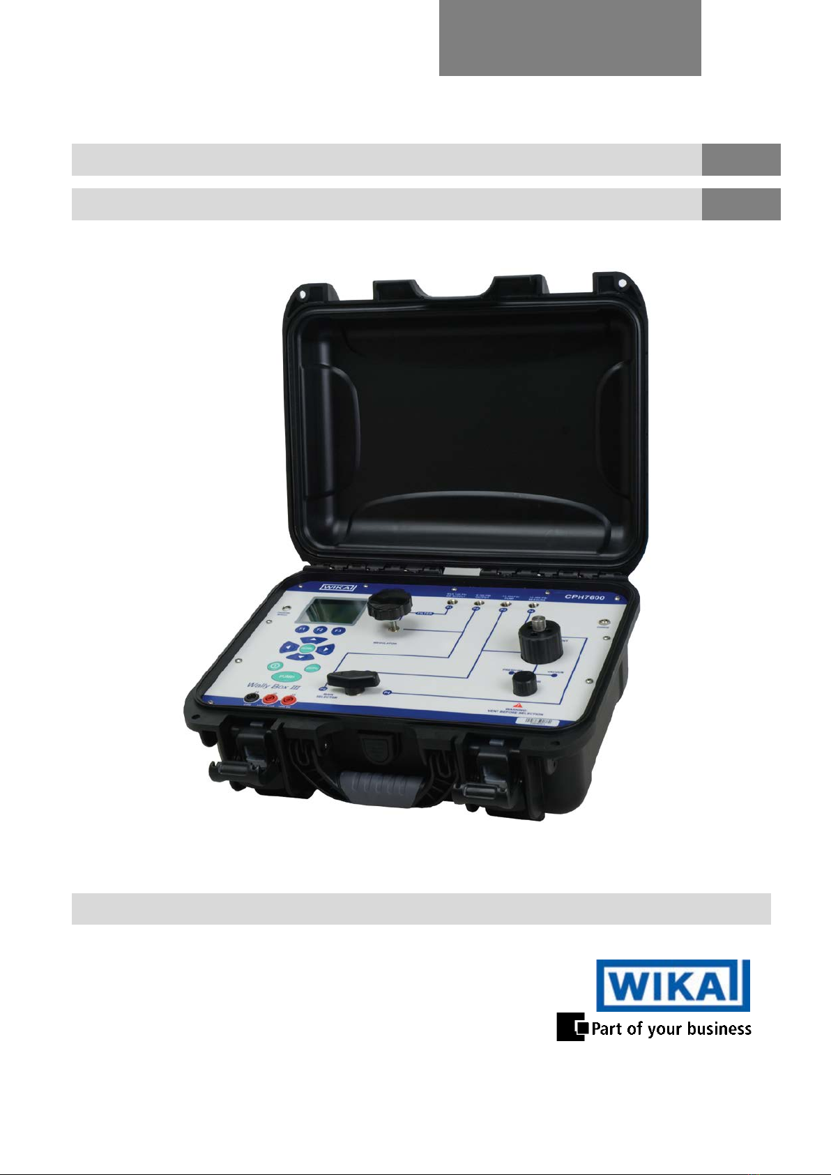
WIKA Operating Instruction, Model CPH7600 3
14051628.01 07/2012 GB/D
C
C
Co
o
on
n
nt
t
te
e
en
n
nt
t
ts
s
s
1General Information ............................................................................................................. 5
2Safety .................................................................................................................................. 6
2.1 Intended use ........................................................................................................................ 7
2.2 Personnel qualification ......................................................................................................... 7
2.3 Special hazards ................................................................................................................... 8
2.4 Labelling / Safety marks ...................................................................................................... 9
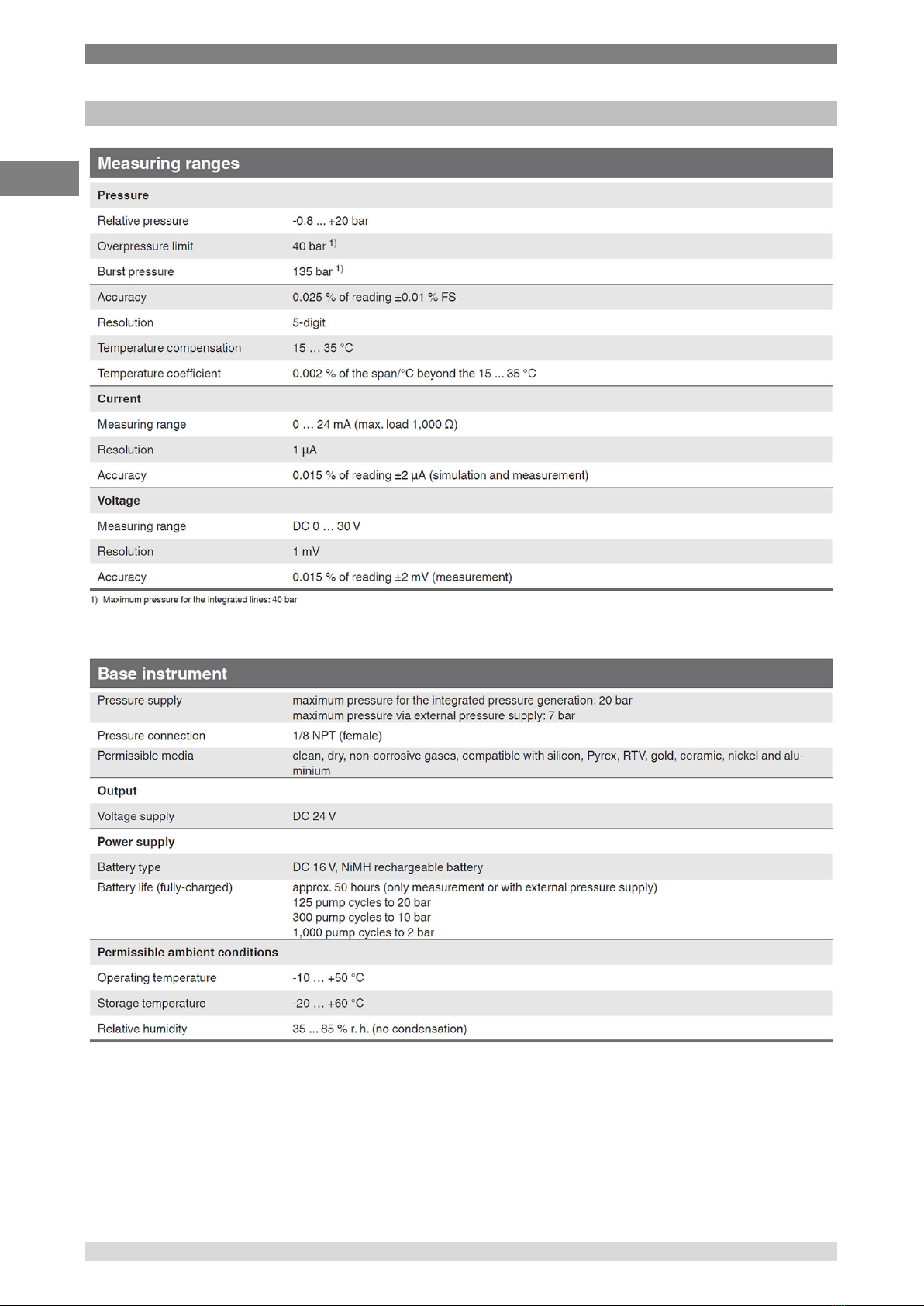
3Specifications .................................................................................................................... 10
4Design and Function .......................................................................................................... 13
4.1 Description ........................................................................................................................ 13
4.2 Scope of delivery ............................................................................................................... 13
4.3 Power supply ..................................................................................................................... 13
4.4 CPH7600 hand-held pressure calibrator, pressure connections ........................................ 14
4.5 CPH7600 hand-held pressure calibrator, keypad ............................................................... 15
4.6 Menu-Structure .................................................................................................................. 16
5Transport, packaging and storage ..................................................................................... 18
5.1 Transport ........................................................................................................................... 18
5.2 Packaging .......................................................................................................................... 18
5.3 Storage .............................................................................................................................. 18
6Commissioning, operation ................................................................................................. 19
6.1 Calibrator display ............................................................................................................... 19
6.1.1 Main display functionality ................................................................................................... 19
6.1.2 Main menu Functionality .................................................................................................... 20
6.2 Using the backlighting........................................................................................................ 21
6.3 Using the "ZERO" function................................................................................................. 21
6.3.1 External pressure module (not absolute) ........................................................................... 21
6.3.2 External pressure module (absolute) ................................................................................. 21
6.4 Other menu controlled functions ........................................................................................ 21
6.4.1 Setting the contrast ............................................................................................................ 22
6.4.2 Locking and unlocking configurations ................................................................................ 22
6.4.3 Saving and recalling settings ............................................................................................. 22
6.4.4 Setting auto shut-off parameters ........................................................................................ 23
6.4.5 Activating and deactivating a display ................................................................................. 23
6.4.6 Damping ............................................................................................................................ 23
6.4.7 Pump limit .......................................................................................................................... 23
6.4.8 HARTTM-Resistor ............................................................................................................... 24
6.5 Basic Setup and initial pressure generation ....................................................................... 24
6.6 Measuring pressure ........................................................................................................... 24
6.6.1 Media compatibility ............................................................................................................ 25
6.6.2 Measuring pressure with external modules ........................................................................ 25
6.7 Measuring and sourcing current (4 ... 20 mA) .................................................................... 26
6.8 Measuring voltage ............................................................................................................. 27
6.9 Performing a pressure switch test ...................................................................................... 28
6.10 Calibrating transmitters ...................................................................................................... 30
6.10.1 Using the mA measurement function ................................................................................. 30
6.10.2 Calibrating a pressure-to-current transmitter ...................................................................... 31
6.10.3 %-Error function ................................................................................................................. 32
6.11 MIN/MAX value capture ..................................................................................................... 35
7Maintenance, cleaning and recalibration ............................................................................ 36
7.1 Maintenance ...................................................................................................................... 36
7.2 Cleaning ............................................................................................................................ 36
7.3 Recalibration ..................................................................................................................... 36
8Faults ................................................................................................................................ 37
GB

Contents
4 WIKA Operating Instruction, Model CPH7600
14051628.01 07/2012 GB/D
9Dismounting, return and disposal ...................................................................................... 37
9.1 Dismounting ...................................................................................................................... 37
9.2 Return ............................................................................................................................... 37
9.3 Disposal ............................................................................................................................ 38
10 Accessories ....................................................................................................................... 38
Declarations of conformity can be found online at www.wika.com.
GB

1 General Information
WIKA Operating Instruction, Model CPH7600 5
14051628.01 07/2012 GB/D
1 General Information
■ The Hand-Held Pressure Indicator model CPH6300 described in the operating instructions has
been manufactured using state-of-the-art technology.
All components are subject to stringent quality and environmental criteria during production. Our
management systems are certified to ISO 9001 and ISO 14001.
■ These operating instructions contain important information on handling the Hand-Held Pressure
Indicator model CPH6300. Working safely requires that all safety instructions and work
instructions are observed.
■ Observe the relevant local accident prevention regulations and general safety regulations for the
range of use of the Hand-Held Pressure Indicator model CPH6300.
■ The operating instructions are part of the instrument and must be kept in the immediate vicinity
of the Hand-Held Pressure Indicator model CPH6300 and readily accessible to skilled personnel
at any time.
■ Skilled personnel must have carefully read and understood the operating instructions, prior to
beginning any work.
■ The manufacturer's liability is void in the case of any damage caused by using the product
contrary to its intended use, non-compliance with these operating instructions, assignment of
insufficiently qualified skilled personnel or unauthorised modifications to the CPH6300.
■ The general terms and conditions, contained in the sales documentation, shall apply.
■ Subject to technical modifications.
■ Factory calibrations/NIST/optional17025 (A2LA accredited) calibrations are carried out in accordance with international
standards.
■ Further information:
- Internet address: www.wika.de / www.wika.com
- Relevant Data Sheet: CT 17.01
- Application consultant: Tel.: (+49) 9372/132-9986
Fax: (+49) 9372/132-8767
E-Mail: [email protected]
GB

1 General Information / 2 Safety
6 WIKA Operating Instruction, Model CPH7600
14051628.01 07/2012 GB/D
Explanation of symbols
WARNING!
... indicates a potentially dangerous situation, which can result in serious
injury or death, if not avoided.
CAUTION!
... indicates a potentially dangerous situation, which can result in light
injuries or damage to equipment or the environment, if not avoided.
DANGER!
... identifies hazards caused by electric power. Should the safety
instructions not be observed, there is a risk of serious or fatal injury.
Information
... points out useful tips, recommendations and information for efficient and
trouble-free operation.
2 Safety
WARNING!
Before installation, commissioning and operation, ensure that the appropriate
reference hand-held pressure calibrator has been selected in terms of measuring
range, design and specific measuring conditions. Non-observance can result in
serious injury and/or damage to equipment.
Further important safety instructions can be found in the individual chapters of these
operating instructions.
GB

2 Safety
WIKA Operating Instruction, Model CPH7600 7
14051628.01 07/2012 GB/D
2.1 Intended use
This hand-held pressure calibrator is used as a calibration instrument for various pressure
measuring instruments.
The hand-held pressure calibrator has been designed and built solely for the intended use
described here, and may only be used accordingly. The technical specifications contained in these
operating instructions must be observed. Should the hand-held pressure calibrator be improperly
handled or operated outside of its technical specifications, it has to be taken out of service
immediately and inspected by an authorised WIKA service engineer.
Handle electronic precision measuring instruments with the required care (protect from humidity,
impacts, strong magnetic fields, static electricity and extreme temperatures, do not insert any
objects into the instrument or its openings). Plugs and sockets must be protected from
contamination.
If the hand-held pressure calibrator is transported from a cold into a warm environment, the
formation of condensation may result in the instrument malfunctioning. Before putting it back into
operation, wait for the instrument temperature and the room temperature to equalise.
The manufacturer shall not be liable for claims of any type based on operation contrary to the
intended use.
2.2 Personnel qualification
WARNING!
Risk of injury should qualification be insufficient!
Improper handling can result in considerable injury and damage to equipment.
■The activities described in these operating instructions may only be carried out by
skilled personnel who have the qualifications described below.
Skilled personnel
Skilled personnel are understood to be personnel who, based on their technical training,
knowledge of measurement and control technology and on their experience and knowledge of
country-specific regulations, current standards and directives, are capable of carrying out the work
described and independently recognising potential hazards.
GB

2 Safety
8 WIKA Operating Instruction, Model CPH7600
14051628.01 07/2012 GB/D
2.3 Special hazards
WARNING!
■ When measuring pressure, make sure that the process pressure line is shut off
and depressurised before it is connected to or disconnected from the pressure
module.
■ Disconnect test leads before changing to another measurement or generation
function.
■ Observe the working conditions in accordance with chapter "3. Specifications".
■ Always operate the device within its overload limits.
■ To ensure problem-free operation, only operate the ProcessCalibrator on battery
power. Only use the mains connection for charging the ProcessCalibrator's
batteries.
■ Do not apply a voltage greater than the specified voltage to the instrument. See
chapter "3. Specifications".
■ Make sure that the test probes never contact a voltage source while the test
leads are connected to the current terminals.
■ Do not use the calibrator if it is damaged. Before using the handheld pressure
calibrator, check that there are no cracks or missing plastic parts on the case.
Pay particular attention to the insulation of the connectors.
■ Select the proper function and correct measuring range for the measurement.
■ Inspect the test leads for damaged insulation or exposed metal. Check the
continuity of the test leads. Damaged test leads should be replaced before using
the hand-held pressure calibrator.
■ When using test probes keep fingers away from the test probe contacts. Keep
your fingers behind the test probes' finger guards.
■ First connect the common lead, and then the live lead. When disconnecting,
remove the live test lead first.
■ Do not use the hand-held pressure calibrator if it is not working properly. The
instrument protection might be compromised. If in doubt, have the instrument
checked.
■ Do not operate the calibrator in areas with explosive gases, vapours or dust.
■ To avoid false readings, which could lead to possible electric shock or personal
injury, charge the rechargeable battery as soon as the battery indicator appears.
■ In order to avoid any possible damage to the pressure calibrator or the test
equipment, use the correct leads, the correct function and the correct range for
the measuring application.
GB

2 Safety
WIKA Operating Instruction, Model CPH7600 9
14051628.01 07/2012 GB/D
DANGER!
Danger of death caused by electric current. Upon contact with live parts, there is a
direct danger of death.
■ Charging using a defective power supply unit (e.g. short circuit from the mains
voltage to the output voltage) can result in life-threatening voltages at the
ProcessCalibrator!
■ Only use the mains connector permitted by WIKA for the Process-Calibrator.
■ Only use a charger that is fully-functional or undamaged.
The safety of the operator may be endangered if, for example:
■ There is visible damage to the instrument.
■ The instrument is not working as specified.
■ The instrument has been stored under unsuitable conditions for an extended period
of time.
If there is any doubt, please return the instrument to the manufacturer for repair or maintenance.
2.4 Labelling / Safety marks
Product label
Explanation of symbols
Before mounting and commissioning the hand-held pressure calibrator
CPH7600, ensure you read the operating instructions!
CE, Communauté Européenne
Instruments bearing this mark comply with the relevant European directives.
This marking on the instruments indicates that they must not be disposed of in
domestic waste. The disposal is carried out by return to the manufacturer or by
the corresponding municipal authorities. See Directive 2002/96/EC.
GB

3 Specifications
10 WIKA Operating Instruction, Model CPH7600
14051628.01 07/2012 GB/D
3 Specifications
GB

3 Specifications
WIKA Operating Instruction, Model CPH7600 11
14051628.01 07/2012 GB/D
GB

3 Specifications
12 WIKA Operating Instruction, Model CPH7600
14051628.01 07/2012 GB/D
For further specifications see WIKA data sheet CT 17.01 and the order documentation.
GB

4 Design and Functions
WIKA Operating Instruction, Model CPH7600 13
14051628.01 07/2012 GB/D
4 Design and Function
4.1 Description
With the Model CPH7600, Wally Box III, WIKA offers a further development of the well-known
Wally Box I and Wally Box II. The Wally Box III is a compact, portable pressure calibrator, which
has been designed for mobile use as well as for stationary workshop and laboratory testing. A
special feature of this test instrument is that it is fitted with two independently- operating pressure
systems. One pneumatic system is designed to be supplied from an external pressure supply,
while the supply pressure of the second system is generated by the integrated electrical pressure
generation. This enables the user to perform different measurement tasks or calibrations,
regardless of external pressure and power supplies.
4.2 Scope of delivery
■ Wally Box III model CPH7600
■ Operating instructions
■ Test cable
■ Calibration hose with ½ NPT male thread connections
■ Adapter set consisting of:
- ⅛ NPT female to ¼ NPT female
- ⅛ NPT female to ¼ BSP female
- ⅛ NPT female to G ½ female
■ PTFE thread seal tape
■ Battery charger
■ 3.1 calibration certificate per DIN EN 10204
Cross-check scope of delivery with delivery note.
4.3 Power supply
Charging
To avoid false measurements, charge the rechargeable batteries as soon as the battery indicator
appears. If the batteries run too low the CPH7600 will automatically shut down.
Use only the original charger supplied by WIKA
GB

4 Design and Functions
14 WIKA Operating Instruction, Model CPH7600
14051628.01 07/2012 GB/D
4.4 CPH7600 hand-held pressure calibrator, pressure connections
(Figure: external pressure supply)
(Figure: Pressure supply with integrated pump)
(Figure: Measuring)
GB

4 Design and Functions
WIKA Operating Instruction, Model CPH7600 15
14051628.01 07/2012 GB/D
4.5 CPH7600 hand-held pressure calibrator, keypad
1 Function keys
Configuration of the calibrator via these soft keys
2 Home key
Return to main menu
3 Arrow keys
Control of the current source/current simulation and adjustment of the pump limit and the
%-error limit
4 ZERO key
Zeroing of the pressure measurement
5 PUMP key
Start-up of the pump operation
6 ON/OFF key
Turning the calibrator on and off
GB

4 Design and Functions
16 WIKA Operating Instruction, Model CPH7600
14051628.01 07/2012 GB/D
4.6 Menu-Structure
see page 17
GB

4 Design and Functions
WIKA Operating Instruction, Model CPH7600 17
14051628.01 07/2012 GB/D
GB

5 Transport, packaging and storage
18 WIKA Operating Instruction, Model CPH7600
14051628.01 07/2012 GB/D
5 Transport, packaging and storage
5.1 Transport
Check hand-held pressure calibrator for any damage that may have been caused by
transport. Obvious damage must be reported immediately.
5.2 Packaging
Do not remove packaging until just before use.
Keep the packaging as it will provide optimum protection during transport (e.g. change
in installation site, sending for repair).
5.3 Storage
Permissible conditions at the place of storage:
■Storage temperature: -20 ... +60 °C
■Humidity: 35 ... 85 % relative humidity (no condensation)
Avoid exposure to the following factors:
■Direct sunlight or proximity to hot objects
■Mechanical vibration, mechanical shock (putting it down hard)
■Soot, vapour, dust and corrosive gases
■Potentially explosive environments, flammable atmospheres
Store the hand-held pressure calibrator in its original packaging in a location that fulfills the
conditions listed above. If the original packaging is not available, pack and store the hand-held
pressure calibrator as described below:
1. Wrap the hand-held pressure calibrator in an antistatic plastic film.
2. Place the hand-held pressure calibrator, along with shock-absorbent material, in the packaging.
3. If stored for a prolonged period of time (more than 30 days), place a bag, containing a desiccant,
inside the packaging.
GB

6 Commissioning, operation
WIKA Operating Instruction, Model CPH7600 19
14051628.01 07/2012 GB/D
6 Commissioning, operation
As soon as the calibrator is turned on, by pressing the ON/OFF key, it will go through a short self-
test routine. During that routine, the display shows the current firmware version, auto-shutdown
status and the range of the internal pressure sensor. The calibrator requires a maximum of 5
minutes warm-up to reach its specified accuracy. Large changes in ambient temperature may
make a longer warm-up period necessary. Pressure ranges should be zeroed each time the
calibrator is started.
6.1 Calibrator display
The calibrator's display consists of two sectors: The menu bar (located along the bottom of the
screen) is used to access the menu system. The main display (the rest of the display) consists of
up to three sub-sectors for the measurement activities. These sub-sectors will be referred to as the
UPPER, MIDDLE and LOWER displays in this document.
Figure 1 shows the location of the different display fields, while are described in the following table.
Figure 1: Display
1 Pressure units
Indication of the pressure unit (selectable from 13 pressure units)
2 Display of span
Indication of the 4 ... 20 mA span (only for the functions mA and mA current loop)
3 Primary parameter
Indication of the current measured parameter
6.1.1 Main display functionality
There are three options for this menu: "MENU", {active display}, and "LIGHT".
6.1.1.1 Using the "MENU" option
The "MENU" option is entry to the rest of the menu system.
6.1.1.2 Using the {active display} option
The {active display} is displayed via the middle option in the menu in the main display. It is used to
select which display on the screen, for example, the ZERO button will be used for.
6.1.1.3 Using the "LIGHT" option
The backlight can be toggled on and off using this key.
GB

6 Commissioning, operation
20 WIKA Operating Instruction, Model CPH7600
14051628.01 07/2012 GB/D
6.1.2 Main menu Functionality
There are three options on the menu, "CONFIG", {active display} and "MORE". The main menu is
the 'home' for the menu display.
6.1.2.1 Setting the {active display}
The {active display} is displayed via the middle option in the menu in the main display. Pressing the
F2 button switches between the {active display}.
6.1.2.2 Setting the {active display} parameters
In order to set the {active display} parameters, select the "CONFIG" option and open the
configuration menu.
Here the "SELECT" option will switch between the available choices for each parameter. The first
parameter is "MODE". Since voltage, current and switch test modes all use the same leads, two of
these functions cannot be used concurrently. The ability to select certain functions is limited and
dependent upon what is already selected in the other display sector. The "NEXT" option is used to
change to the second parameter. Only the pressure modes have a second parameter.
Within any single display sector, the following modes are available:
P[1] = integrated pressure sensor
[EXT] = pressure with external pressure module
P[1] ST = switch test with integrated sensor
[EXT] ST = switch test with external pressure module
Current functions are only available on the lower display:
mA measurement = current measurement without power supply
mA w/24V = current measurement with power supply
mA Source = current source
mA sim = mA simulation using an external supply from the instrument under test
VOLT = voltage measurement
The following table shows which functions are available concurrently. An "--" in a column indicates
that the mode in the active display will not be available for selection if the mode in that row is in use
in any other display sector.
Active display
Other Displays
P[1] [EXT] P[1]
ST
[EXT]
ST
mA mA-loop Volt
P[1]
[EXT]
P[1] ST
--
--
--
--
--
[EXT] ST
--
--
--
--
--
mA
--
--
--
--
mA-loop
--
--
--
--
Volt
--
--
--
--
GB
This manual suits for next models
1
Table of contents
Languages:
Other WIKA Test Equipment manuals

WIKA
WIKA CPH65I0 User manual

WIKA
WIKA PASCAL ET-P User manual

WIKA
WIKA CPH8000-ET User manual

WIKA
WIKA CPH6000 User manual

WIKA
WIKA CPB 5800 User manual

WIKA
WIKA CPH7650 User manual

WIKA
WIKA DELTA-comb DPGS40TA User manual

WIKA
WIKA CPB 5000 User manual

WIKA
WIKA CPH7000 User manual

WIKA
WIKA Pascal ET User manual