WimTec PROOF P4 User manual

PROOF P4
Montage- und Bedienungsanleitung
DE
Assembly and operating instructions
EN

2 Dusche-Paneel WimTec PROOF P4
DE
PROOF P4
Gratulation zum Kauf Ihres Selbstschluss-Dusche-Paneels
WimTec PROOF P4.
Damit Sie jahrelang Freude mit dieser hochwertigen Armatur
haben, empfehlen wir Ihnen folgende Punkte bei der Reinigung
und Pflege zu beachten:
milde, seifenhaltige Reinigungsmittel verwenden
keine kratzenden, scheuernden oder säurehaltigen
Reinigungs- oder Desinfektionsmittel verwenden
nur mit weichem Schwamm oder Tuch behandeln
keine Reinigung mit Dampfstrahlgeräten
Diese Anleitung ist gültig für folgende Produkte:
WimTec PROOF P4 - 6 V Art.Nr. 120 998
WimTec PROOF P4 - 12 V Art.Nr. 121 018
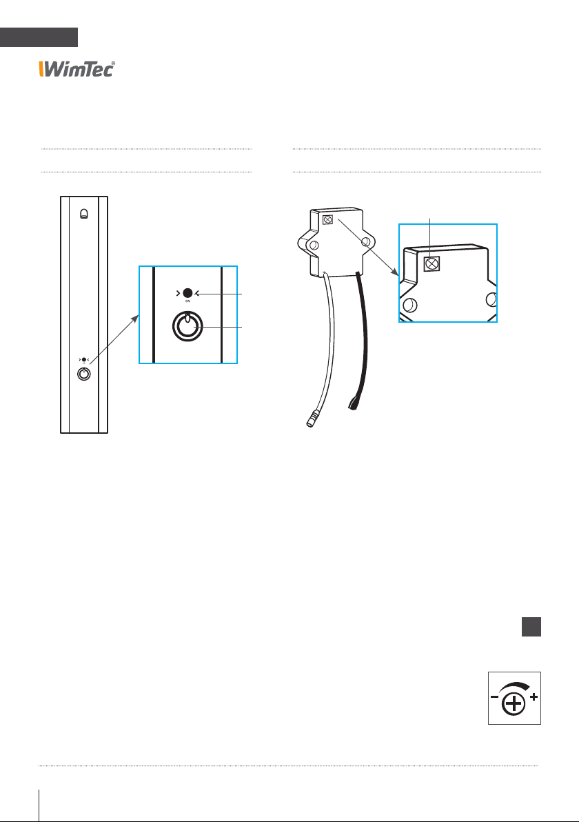
Lieferumfang:
Aufputz-Aluminiumgehäuse mit integrierter Elektronik, Thermostat
mit Heißwassersperre, vandalensicherer Duschkopf, 1 Magnetventil,
Anschlussmodul für externe 12 V Versorgung oder 6 V Batteriemo-
dul inkl. Batterie und Befestigungsteile.
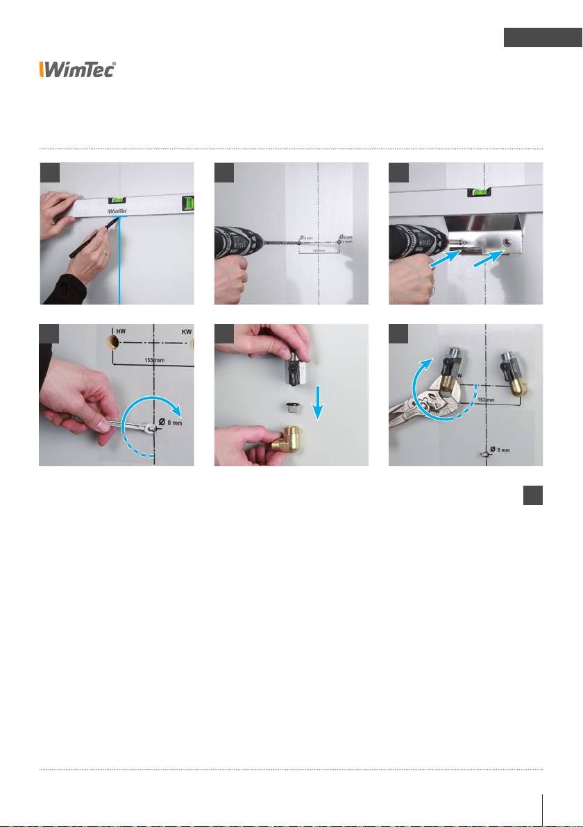
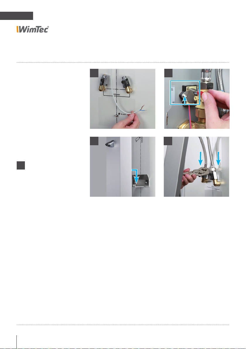
Wichtige Installationshinweise:
UP-Dose für optionales Netzteil außerhalb des Schutzbereichs vor-
sehen. Die Montage und Installation darf nur durch einen konzessi-
onierten Fachbetrieb gemäß DIN 1988, ÖVE/ÖNORM E8001 sowie
VDE 0100 Teil 701 erfolgen. Bei der Planung und Errichtung von
Sanitäranlagen sind die entsprechenden örtlichen, nationalen und
internationalen Normen und Vorschriften zu beachten!
Allgemeine Hinweise
Es gelten die „Allgemeinen
Installationsbedingungen“
gemäß www.wimtec.com.
!

Dusche-Paneel WimTec PROOF P4 3
DE
PROOF P4
6 V Batteriebetrieb:
Batterie: 6 V Lithium CR-P2 (im Lieferumfang enthalten)
Batterielebensdauer: ca. 100.000 Spülungen (max. 2 Jahre)
12 V externe Versorgung:
Betriebsspannung: über Netzteil 230 V 50 Hz / 12 V=
Art.Nr. 117 899 - Netzteil für eine Steuerung
Art.Nr. 113 792 - Netzteil für bis zu 5 Steuerungen
Leistungsaufnahme: max. 3 W
Weitere technische Daten:
Magnetventil: Kartusche 6 V
Nah-Ansprechbereich: 1 - 3 cm
Laufzeit: 30 s voreingestellt (10 s - 60 s einstellbar)
Fließdruck: 0,05 - 0,6 MPa (0,5 - 6 bar)
Statischer Druck: max. 0,8 MPa (8 bar)
Durchflussmenge: ca. 9 l/min bei 0,3 MPa (3 bar)
Wassertemperatur: max. 70 °C (max. 80 °C für max. 10 min)
Wasserzulauf: R 1/2“ IG
Material: Paneel: Aluminium eloxiert, Brausekopf und
Thermostatgriff: Messing verchromt
Temperatureinstellung: Thermostat mit Heißwassersperre (nicht frostbeständig)
Technische Daten

4 Dusche-Paneel WimTec PROOF P4
DE
PROOF P4
A
B
A On-Taster zum Einschalten der Dusche.
B Thermostatgriff zur Temperatur-
regelung mit Taste zum Entriegeln
der 38 °C Sicherheitssperre.
C Zeit-Regler
Generell gilt für den Zeit-Regler:
Gegen den Uhrzeiger-
sinn zum Reduzieren.
Im Uhrzeigersinn zum
Erhöhen.
!
C
Legende
Elektronikmodul:Duschepaneel:

Dusche-Paneel WimTec PROOF P4 5
DE
PROOF P4
Einstellung der Laufzeit
C. Zeit-Regler
für die Laufzeit auf
30 s voreingestellt
(10 s - 60 s einstellbar).
Nach Ablauf der eingestellten
Laufzeit schaltet die Dusche-
armatur automatisch ab.
Einstellregler:
Selbstschluss-Funktion
Wasserfluss startet
Sobald der Benutzer auf den
Taster tippt.
Wasserfluss stoppt
Nach Ablauf der eingestellten
Laufzeit.
60 cm60 cm60 cm60 cm
Laufzeit
um 07:00 Uhr

6 Dusche-Paneel WimTec PROOF P4
DE
PROOF P4
Abmessungen Alle Maße in mm:
ACHTUNG!
Netzteil 230 V / 12 V nicht
in Duschepaneel oder
Schutzbereichen anbringen.
!
Eine Nachrüstung ist auf bestehenden Anschlüssen im Standardmaß
150 mm möglich.
* Bei externer Versorgung E-Anschluss 12 V= vorsehen.
185
166
300
1300
810
90
80
405
65
½"
40
80
1190
325
256
* E-Anschluss
12 V=

Dusche-Paneel WimTec PROOF P4 7
DE
PROOF P4
Montage
1 2 3
5 6
1. Mittellinie und Oberkante des Paneels anzeichnen.
2. Selbstklebende Bohrschablone aufkleben.
3x Ø 8 mm bohren und Dübel einsetzen.
3. Montagebügel mit Befestigungsschraube und Beilag-
scheiben befestigen.
4. Stockschraube für Befestigung eindrehen und Befesti-
gungsbügel für Batteriemodul dabei einhängen.
5. Korbfilter in 90° Anschlusswinkel einsetzen und Ab-
sperrung aufdichten.
6. Anschlusswinkel mit Absperrung aufdichten und in Zulei-
tungen einschrauben – Vorabsperrung dabei schräg nach
innen ausrichten.
ACHTUNG!
Folgende Schritte unbe-
dingt in beschriebener
Reihenfolge ausführen!
!
4

8 Dusche-Paneel WimTec PROOF P4
DE
PROOF P4
Montage: 6 V Batterie-Version Art.Nr. 120 998
7. Gewünschte Laufzeit am Elektronikmodul einstellen
(siehe S. 5).
8. Dusche-Paneel in die vordere Bügellasche einhängen.
9. Flexschläuche mit beigelegter Dichtung an Wasserzuleitung
anschließen.
10. Batteriemodul anstecken. (Sicherheitsschließimpuls beim
Magnetventil erfolgt).
7
109
8
ACHTUNG!
Folgende Schritte unbe-
dingt in beschriebener
Reihenfolge ausführen!
12 V Netz-Version
weiter auf Seite 10.
!
i

Dusche-Paneel WimTec PROOF P4 9
DE
PROOF P4
Montage: 6 V Batterie-Version Art.Nr. 120 998
15
131211
14
11. Kontrollieren, ob Vorabsperrungen geöffnet sind
(Riegel stehen parallel zur Flussrichting).
12. Dusche-Paneel in die hintere Bügellasche einhängen.
ACHTUNG! Keine Kabel oder Schläuche quetschen
oder knicken.
13. Batteriemodul mit Beilagscheibe und Flügelmutter
an der Stockschraube befestigen.
14. Hauptwasserleitung öffnen.
15. Funktionstest durchführen.
ACHTUNG!
Folgende Schritte unbe-
dingt in beschriebener
Reihenfolge ausführen!
!

10 Dusche-Paneel WimTec PROOF P4
DE
PROOF P4
Montage: 12 V Netz-Version Art.Nr. 121 018
7. Anschlusskabel (Kabeltyp: 2 x 0,5 mm2) einziehen
und am Netzteil (Art.Nr. 117 899 für 1 Steuerung, oder
Art.Nr. 113 792 für bis zu 5 Steuerungen) anschließen.
Achtung: Stromversorgung muss abgeschaltet sein und
Netzteil darf nicht im Duschepaneel bzw. Schutzbereich
verbaut werden!
HINWEIS: zum Deaktivieren der Dusche bei Reinigungsar-
beiten, wird empfohlen einen Schalter (Schlüsselschalter)
vor dem Netzteil zu installieren.
8. Gewünschte Laufzeit am Elektronikmodul einstellen
(siehe S. 5).
9. Dusche-Paneel in die vordere Bügellasche einhängen.
10. Flexschläuche mit beigelegter Dichtung an Wasserzuleitung
anschließen.
8
109
7
ACHTUNG!
Folgende Schritte unbe-
dingt in beschriebener
Reihenfolge ausführen!
!

Dusche-Paneel WimTec PROOF P4 11
DE
PROOF P4
Montage: 12 V Netz-Version Art.Nr. 121 018
1614
13
11
+-
15
11. Elektro-Anschluss am Elektronikmodul herstellen
(Auf +/- Polung achten) und Stromversorgung einschalten
(Sicherheitsschließimpuls beim Magnetvenil erfolgt).
12. Kontrollieren, ob Vorabsperrungen geöffnet sind
(Riegel stehen parallel zur Flussrichtung).
13. Dusche-Paneel in die hintere Bügellasche einhängen.
ACHTUNG! Keine Kabel oder Schläuche quetschen
oder knicken.
14. Duschepaneel von unten mit Beilagscheibe und
Flügelmutter an der Stockschraube sichern.
15. Hauptwasserleitung öffnen.
16. Funktionstest durchführen.
ACHTUNG!
Folgende Schritte unbe-
dingt in beschriebener
Reihenfolge ausführen!
!
12

12 Dusche-Paneel WimTec PROOF P4
DE
PROOF P4
Ersatzteile
Art.Nr.:
120 165
120 356
231 205
231 312
230 741
230 987
117 899
113 792
107 159
Bezeichnung
Duschkopf WimTec PROOF
Elektronikmodul
Magnetventil
Magnetventil-Adapter
6 V Lithium Batterie
Batteriemodul 6 V
Netzteil (1-fach)
Netzteil (5-fach)
Thermostat

Shower paneel WimTec PROOF P4 13
EN
PROOF P4
Bezeichnung
Duschkopf WimTec PROOF
Elektronikmodul
Magnetventil
Magnetventil-Adapter
6 V Lithium Batterie
Batteriemodul 6 V
Netzteil (1-fach)
Netzteil (5-fach)
Thermostat
Congratulations on purchasing the WimTec PROOF P4.
In order to ensure that you will be able to enjoy this high-quality
product for many years, please take note of the following cleaning
and maintenance recommendations:
Use mild cleaning agents containing soap
Do not use abrasive, scrubbing, sealing or acidic
cleaning agents or disinfectants
Clean the fitting with a soft sponge or cloth only
Do not use steam cleaners
This manual is valid for the following products:
WimTec PROOF P4 - 6 V Art.No. 120 998
WimTec PROOF P4 - 12 V Art.No. 121 018
Delivery scope:
On wall aluminium housing with integrated electronics, thermostat
with hot-water barrier, vandalproof shower head, 1 magnetic valve,
connection module for external supply or 6 V battery module incl.
battery and mounting material.
Important installation notes:
Mounting and installation may only be performed by a qualified
service provider in accordance with DIN 1988, ÖVE/ÖNORM E8001
and VDE 0100 Part 701. When planning and installing sanitary
facilities, all relevant local, national and inter-national standards
and provisions must be observed! Provide for 230 V / 12 V power
unit outside of the protected zone.
General notes
The “General installation
terms and conditions”
provided at
www.wimtec.com apply.
!

14 Shower paneel WimTec PROOF P4
EN
PROOF P4
6 V battery operation:
Battery: 6 V Lithium CR-P2 (included in scope of supply)
Battery life: approx. 100.000 flushings (max. 2 years)
12 V external supply:
Operating voltage: via power supply 230 V 50 Hz / 12 V=
Art.No. 117 899 - power supply for one control unit
Art.No. 113 792 - power supply for up to 5 control units
Power consumption: max. 3 W
Further technical specifications:
Magnetic valve: cartridge 6 V
Close-Active range: 1 - 3 cm
Flushing stop: set to 30 s by default (configurable from 10 s - 60 s)
Flow rate: 0,05 - 0,6 MPa (0,5 - 6 bar)
Static pressure: max. 0,8 MPa (8 bar)
Flow rate: 9 l/min at 0,3 MPa (3 bar)
Water temperature: max. 70 °C (max. 80 °C for max. 10 min)
Water inlet: R 1/2“ IG
Material: Panel: Aluminium anodized, fittings: chrome
Temperature adjustment: Thermostat with hot-water barrier (not frost resistant)
Technical specifications

Shower paneel WimTec PROOF P4 15
EN
PROOF P4
A
B
A ON/OFF button to turn the shower
ON/OFF.
B Thermostat knob to adjust the
temperature, including a button for
bypassing the 38 °C safety lock.
C Time control
C
Legend
Electronics module:Shower panel:
The general rule applies to all controls:
Move counterclockwise to
decrease the setting.
Move clockwise to increase
the setting.
!

16 Shower paneel WimTec PROOF P4
EN
PROOF P4
Configuring the programs & functions
C. Time control
set to a duration of 30 s by
default (configurable from
10–60 s).
After the configured maximum
flow time has elapsed, the
water stops automatically to
prevent unintentional conti-
nuous activation.
DIP switches:
Selfclosing function
Water starts flowing
As soon as you tap the button.
Water stops flowing
After the configured flow time
has elapsed.
60 cm60 cm60 cm60 cm
Duration
um 07:00 Uhr

Shower paneel WimTec PROOF P4 17
EN
PROOF P4
Dimensions All dimensions in mm:
Do not install the 230 V /
12 V power supply in the
shower panel or protected
zones.
!
Retrofitting using existing connections can be performed for the
standard size 150 mm.
* Provide for 12 V= elec. connection.
185
166
300
1300
810
90
80
405
65
½"
40
80
1190
325
256
* E-connection
12 V=

18 Shower paneel WimTec PROOF P4
EN
PROOF P4
Assembly
1 2 3
5 6
1. Mark the centre line and upper edge of the panel on the
wall.
2. Attach the self-adhesive drilling template.
Drill 3x Ø 8-mm holes and insert dowels.
3. Attach mounting bracket using the screws and washers.
4. Screw in the hanger screw.
5. Insert the basket filter into the 90° angled connector and
attach locking pin at the top.
6. Seal off the angled connector by attaching the locking
pin and screw the connector into the inlets, aligning the
locking pins towards the inside at an angle as indicated.
ATTENTION!
Perform the following steps
in the order indicated!
!
4

Shower paneel WimTec PROOF P4 19
EN
PROOF P4
Assembly: 6 V battery version Art.No. 120 998
7. Configure the desired time at the electronics module.
(see p. 16)
8. Hook the shower panel into the rear bracket strap.
ATTENTION! Be careful not to bend or crimp any cables or
tubes.
9. Connect the flexible tubes and included valves to the water
inlets.
10. Plug-in the battery module. (safety locking mechanism of the
magnetic valve starts).
7
109
8
ATTENTION!
Perform the following steps
in the order indicated!
!

20 Shower paneel WimTec PROOF P4
EN
PROOF P4
Assembly: 6 V battery version Art.No. 120 998
15
131211
14
11. Check whether the stop valves are open (knobs are aligned
alongside the water pipes).
12. Hook the shower panel into the rear bracket strap.
ATTENTION! Be careful not to bend or crimp any cables or
tubes.
13. Secure the battery module at the hanger screw using a
washer and wing nut.
14. Open the main water valve.
15. Perform a system test.
ATTENTION!
Perform the following steps
in the order indicated!
!
Table of contents
Languages:
Other WimTec Bathroom Fixture manuals

WimTec
WimTec SanTec FLUSH SLK Manual

WimTec
WimTec SanTec Outdoor User manual

WimTec
WimTec OCEAN S7 User manual

WimTec
WimTec 114 683 User manual

WimTec
WimTec OCEAN S6 User manual

WimTec
WimTec PROOF S4 Planning guide

WimTec
WimTec SanTec PROOF S4 User manual

WimTec
WimTec PROOF S6 User manual

WimTec
WimTec OCEAN P10 User manual

WimTec
WimTec SanTec FLUSH User manual
Popular Bathroom Fixture manuals by other brands

Hans Grohe
Hans Grohe MySelect S 150 Semipipe 27239000 Instructions for use/assembly instructions

KEUCO
KEUCO Plan Care 35901 Mounting instruction

Bossini
Bossini Dream-Light manual

Longevity
Longevity SS-55P-LAT-B/C instruction manual

Hewi
Hewi 805 Classic Series installation instructions

Mira
Mira Minilite BIR Installation and user guide