WOOSIM Porti-M200H User manual

http://www.woosim.com
T
Th
he
er
rm
ma
al
lP
Pr
ri
in
nt
ti
in
ng
gM
Me
ec
ch
ha
an
ni
is
sm
m
Porti-M200H
O
Op
pe
er
ra
at
to
or
r’
’s
sM
Ma
an
nu
ua
al
l
W
WO
OO
OS
SI
IM
MS
SY
YS
ST
TE
EM
MI
In
nc
c.
.P
Po
or
rt
ti
i-
-M
M2
20
00
0H
H.
.
㩷

http://www.woosim.com 1
Copyright
Porti-M200H is Thermal Printing Mechanism operator’s manual
Copyright
ཱྀ
2005 by Woosim System Inc.
All rights reserved. The information contained in this manual is the property of
Woosim System Inc. and may not be reproduced in whole or in part without the prior
written permission of Woosim System Inc.
Trademark
a
ar
re
eg
gi
is
st
te
er
re
ed
dt
tr
ra
ad
de
em
ma
ar
rk
ko
of
fW
Wo
oo
os
si
im
mS
Sy
ys
st
te
em
mI
In
nc
c.
.
All other trademark is the properties of their respective companies.
N
No
ot
ti
ic
ce
e
The contents of this manual are subject to change without notice.
㩷
㩷
㩷 㩷
T
To
oc
co
on
nt
ta
ac
ct
to
ou
ur
rT
Te
ec
ch
hn
ni
ic
ca
al
lS
Su
up
pp
po
or
rt
t:
:
Tel : (+82-2) 2107-3700 Fax : (+82-2) 2107-3707
Address : #501, Daerung Technotown 3th,
448, Gasan-Dong, GeumChun-Ku, Seoul, Korea

http://www.woosim.com 2
TableofContents
I
IN
NT
TR
RO
OD
DU
UC
CT
TI
IO
ON
N
GENERALSPECIFICATION ........................................................................................................................................4G
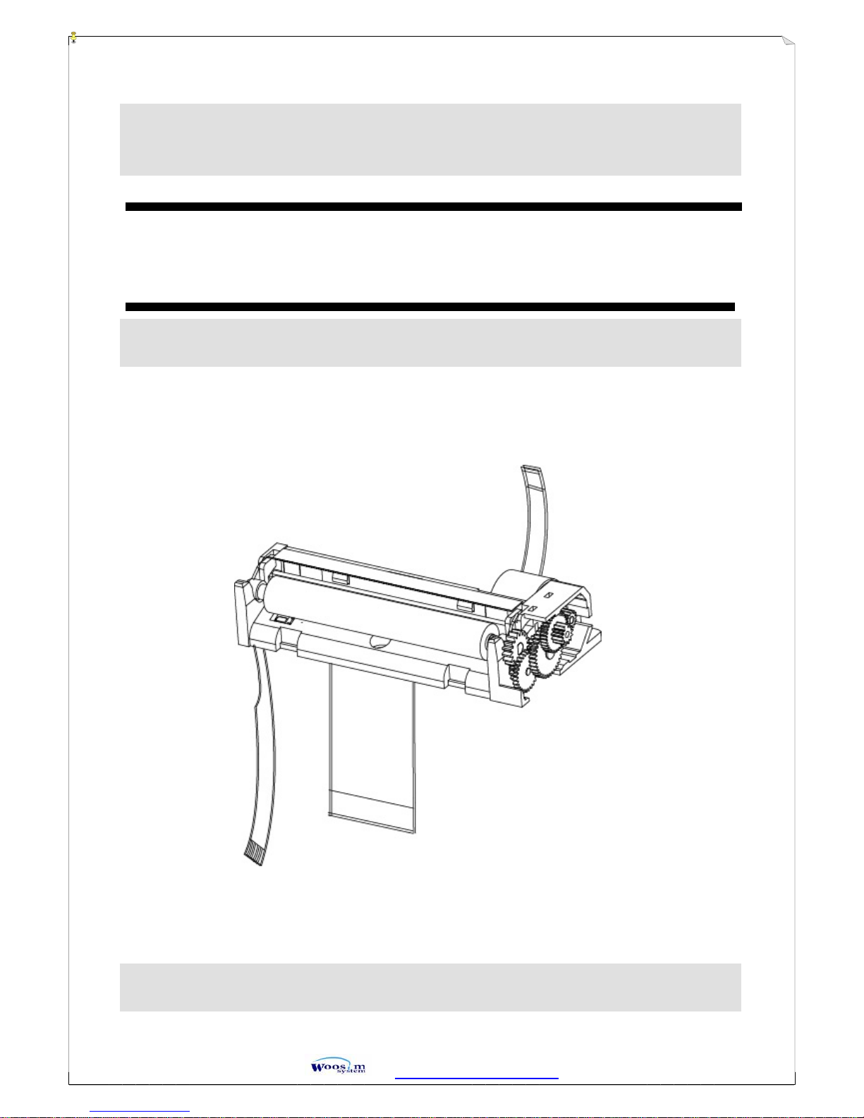
DESCRIPTION OFTHE MECHANISM......................................................................................................................5G
MAIN FEATURES...........................................................................................................................................................5G
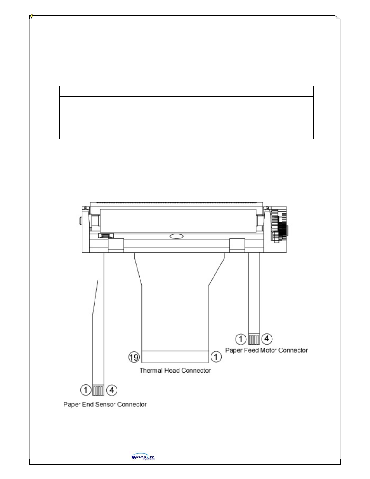
1. CONNECTIONS ..........................................................................................................................................................6G
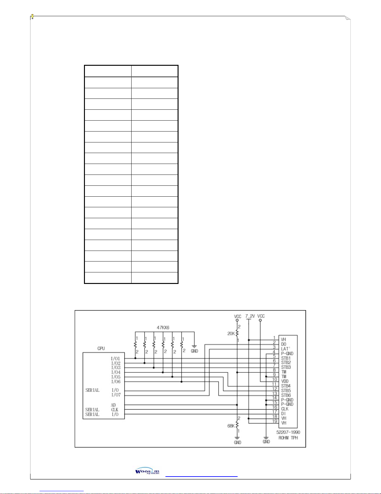
1.1 Thermal print head....................................................................................................................................................7G
1.1.1 Thermal head connectors pin assignments.........................................................................................................7G
1.1.2 Thermal head block diagram..............................................................................................................................7G
1.2 Paper Feed Motor Connector....................................................................................................................................8G
1.2.1 Paper feed motor connector’s pin assignments..................................................................................................8G
1.2.2 Paper feed motor block diagram........................................................................................................................8G
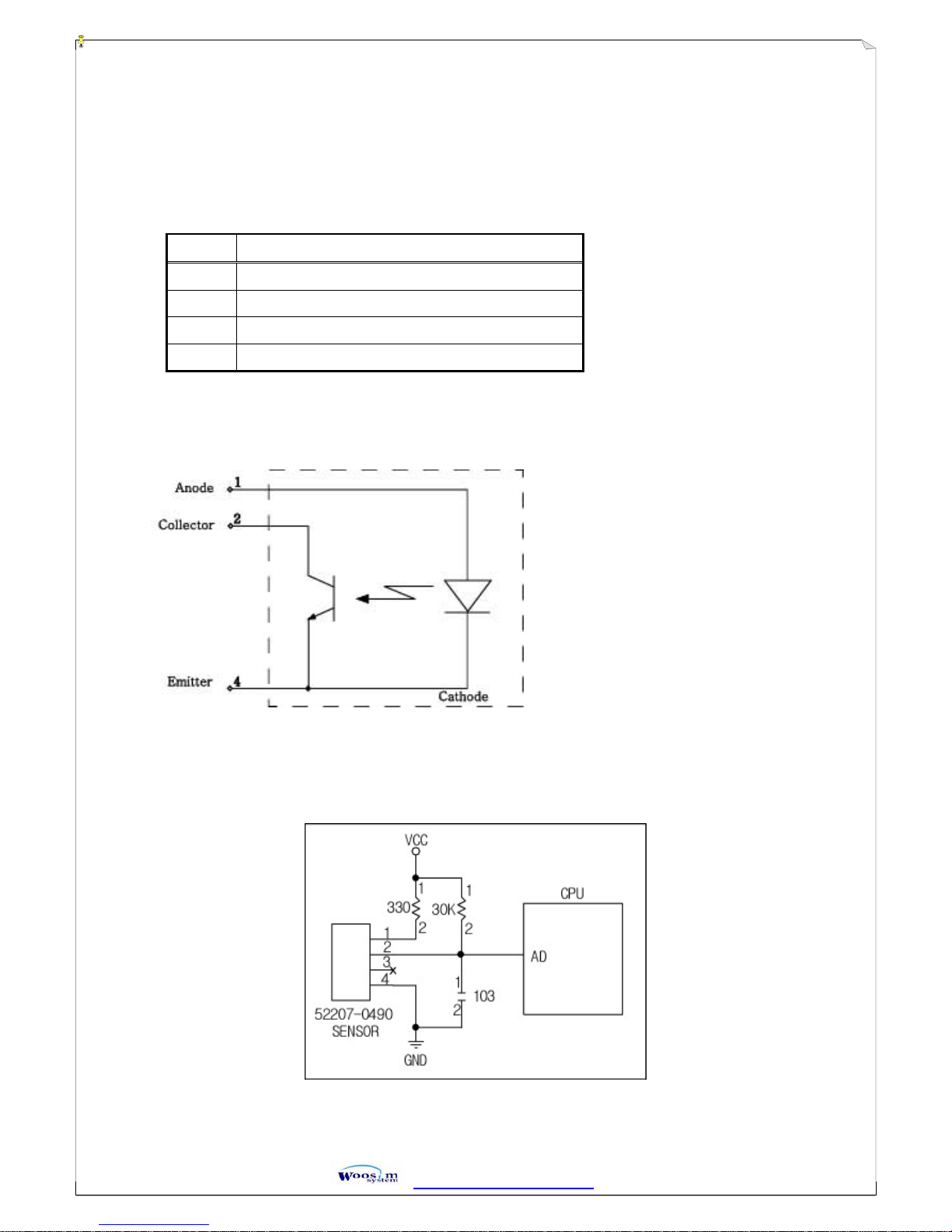
1.3 Paper end Sensor Connector.....................................................................................................................................9G
1.3.1 Paper end sensor connector’s pin assignments ..................................................................................................9G
1.3.2 Paper end sensor block diagram ........................................................................................................................9G
2. PRINT HEAD .............................................................................................................................................................10G
2.1 Outlines...................................................................................................................................................................10G
2.2 Maximum Conditions at 25................................................................................................................................10G
2.3 Typical Printing Conditions at 25.......................................................................................................................10G
2.4 Ambient Conditions................................................................................................................................................11G
2.5 Print Quality (at standard Conditions and operation temperature is higher or equal 5)...................................... 11G
2.6 Printhead Life on Standard Printing Conditions..................................................................................................... 11G
2.7 Operation Precautions.............................................................................................................................................12G
2.8.................................................................................................................................................................................14G
2.8.1 Circuit Diagram...............................................................................................................................................14G
2.8.2 Electrical characteristics of Circuit..................................................................................................................15G
2.8.3 Timing chart.....................................................................................................................................................16G
2.8.4 THERMISTOR SPECIFICATION..................................................................................................................17G
3. PAPER FEED MOTOR.............................................................................................................................................18G
3.1 Ratings....................................................................................................................................................................18G
3.2 Electrical characteristics.........................................................................................................................................18G
3.3 Mechanical properties.............................................................................................................................................19G
3.4 Excitation ( 2 phase, Full step ) ..............................................................................................................................19G
3.5 Environmental properties........................................................................................................................................19G
4. PAPER END SENSOR...............................................................................................................................................20G

http://www.woosim.com 3
4.1 Maximum rating .....................................................................................................................................................20G
4.2 Electron-optical characteristics...............................................................................................................................20G
5. DIMENSIONS ............................................................................................................................................................21G
6. DISASSEMBLEYAND ASSEMBLY .......................................................................................................................22G
6.1 Assembly ................................................................................................................................................................22G
6.2 Disassembly............................................................................................................................................................22G
6.2.1 Remove the Platen...........................................................................................................................................22G
6.2.2 Remove the Sensor..........................................................................................................................................22G
6.2.3 Remove the TPH and the Stepping Motor.......................................................................................................23G
6.2.4 Remove the Fix Spring....................................................................................................................................23G
Figure A.1 EXPLODED DIAGRAM OF Porti-M200H ..............................................................................................24G

http://www.woosim.com 4
I
IN
NT
TR
RO
OD
DU
UC
CT
TI
IO
ON
N
G
GE
EN
NE
ER
RA
AL
LS
SP
PE
EC
CI
IF
FI
IC
CA
AT
TI
IO
ON
N
Item Specification
Printing Method Direct thermal line printing
Printing width 48.0
r
0.2mm
Head Configuration (dots/line) 384
Dot Pitch 0.125 mm
Printing Speed 50 mm/s (MAX)
Paper Width 57
r
0.5 mm
Paper feed method Friction feed
Head temperature sensor Thermistor
Paper detection Reflecting photosensor
Heater resistance 176
ൎ
4%
Number of strobes 6
External dimensions (W x D x H) 68.1 x 16.8 x 32.7 mm
Weight 32.5g
Life/Reliability 50Km
Recommended paper TSP-F50US or equivalent
Input Power 9VDC/ MAX 3A

http://www.woosim.com 5
D
DE
ES
SC
CR
RI
IP
PT
TI
IO
ON
NO
OF
FT
TH
HE
EM
ME
EC
CH
HA
AN
NI
IS
SM
M
M
MA
AI
IN
NF
FE
EA
AT
TU
UR
RE
ES
S
ഘ
High speed up 50mm/sec (MAX)
ഘ
High resolution 8dots/mm, 203dpi
ഘ
Paper detection photo-sensor
ഘ
Life 50 km Printed paper
ٻ
The main characteristics of the Porti-M200H thermal printing mechanism are definitely the reliability,
the quality and the long lasting performance, making it the suitable product for industrial environments
such as weighting, control, safety systems, as well as medical and portable applications.
㩷

http://www.woosim.com 6
1. C
CO
ON
NN
NE
EC
CT
TI
IO
ON
NS
S
(Figure 1)
The Porti-M200H mechanism has 3 interface connectors, Print head connector and Paper feed motor
control connector, Paper end sensor. In the table below are described the connector specifications and
functions:
㩷 㩷
(
(T
Ta
ab
bl
le
e1
1)
)
No. Connector Pin No. Type
1 Thermal head connector 19 Connector for FPC (pitch 1mm) such as molex
connector series 52207-1990
2 Paper feed motor connector 4
3 Paper end sensor connector 4
Connector for FPC (pitch 1mm) such as molex
connector series 52207-0490

http://www.woosim.com 7
1
1.
.1
1T
Th
he
er
rm
ma
al
lp
pr
ri
in
nt
th
he
ea
ad
d
1
1.
.1
1.
.1
1T
Th
he
er
rm
ma
al
lh
he
ea
ad
dc
co
on
nn
ne
ec
ct
to
or
rs
sp
pi
in
na
as
ss
si
ig
gn
nm
me
en
nt
ts
s
(TABLE 2)
PIN No. SIGNAL
1 VH
2 DO
3 /LAT
4 GND
5 STB1
6 STB2
7 STB3
8 TM
9 TM
10 VDD
11 STB4
12 STB5
13 STB6
14 GND
15 GND
16 CLK
17 DI
18 VH
19 VH
1
1.
.1
1.
.2
2T
Th
he
er
rm
ma
al
lh
he
ea
ad
db
bl
lo
oc
ck
kd
di
ia
ag
gr
ra
am
m

http://www.woosim.com 8
1
1.
.2
2P
Pa
ap
pe
er
rF
Fe
ee
ed
dM
Mo
ot
to
or
rC
Co
on
nn
ne
ec
ct
to
or
r
1
1.
.2
2.
.1
1P
Pa
ap
pe
er
rf
fe
ee
ed
dm
mo
ot
to
or
rc
co
on
nn
ne
ec
ct
to
or
r’
’s
sp
pi
in
na
as
ss
si
ig
gn
nm
me
en
nt
ts
s
1
1.
.2
2.
.2
2P
Pa
ap
pe
er
rf
fe
ee
ed
dm
mo
ot
to
or
rb
bl
lo
oc
ck
kd
di
ia
ag
gr
ra
am
m
Pin No. Signal Phase
1 PhaseA
2 PhaseA
3 Phase B
4 Phase B
(
(T
Ta
ab
bl
le
e1
1.
.2
2)
)
(
(F
Fi
ig
gu
ur
re
e1
1.
.2
2)
)

http://www.woosim.com 9
1
1.
.3
3P
Pa
ap
pe
er
re
en
nd
dS
Se
en
ns
so
or
rC
Co
on
nn
ne
ec
ct
to
or
r
1
1.
.3
3.
.1
1P
Pa
ap
pe
er
re
en
nd
ds
se
en
ns
so
or
rc
co
on
nn
ne
ec
ct
to
or
r’
’s
sp
pi
in
na
as
ss
si
ig
gn
nm
me
en
nt
ts
s
1
1.
.3
3.
.2
2P
Pa
ap
pe
er
re
en
nd
ds
se
en
ns
so
or
rb
bl
lo
oc
ck
kd
di
ia
ag
gr
ra
am
m
Pin No. Signal Name
1 Vcc
2 Signal ( Open collector)
3 N.C
4 GND
(
(T
Ta
ab
bl
le
e1
1.
.3
3)
)
(
(F
Fi
ig
gu
ur
re
e1
1.
.3
3)
)

http://www.woosim.com 10
2
2.
.P
PR
RI
IN
NT
TH
HE
EA
AD
D
2
2.
.1
1O
Ou
ut
tl
li
in
ne
es
s
2
2.
.2
2M
Ma
ax
xi
im
mu
um
mC
Co
on
nd
di
it
ti
io
on
ns
sa
at
t2
25
5
2
2.
.3
3T
Ty
yp
pi
ic
ca
al
lP
Pr
ri
in
nt
ti
in
ng
gC
Co
on
nd
di
it
ti
io
on
ns
sa
at
t2
25
5
* Mechanical Conditions
* Thermal Paper use for Evaluation
- OJI KF50-HAD or Equivalent
Heat Element Structure : 2 heaters/dots
Number of Heat Elements : 384 dots
Heat Element Pitch : 0.125mm (8 dots/mm)
Pitch Width : 48mm
0.2mm
Average Resistance Value(Rave) : 176
ൎ
4%
Circuit Diagram : Fig. 2.8
Pinout Diagram : Table 2
Electrical Characteristics of Circuit : Table 2.8, Fig. 2.8.3
Thermistor :
ٻٻ ٻ ٻ ٻ ٻٻٻٻٻٻٻٻٻ ٻ
Table 2.8.4, Fig. 2.8.4
㩷
Item Maximum Conditions Unit Conditions
Print Cycle (S.L.T.) 1.25 ms/line
Supply Energy 0.20 mJ/dot Tsub = 25
Supply Voltage 8.5 V Just after battery charge
7.2V at all time
Substrate Temperature 65
Thermistor Temperature
Number of Dots to be
Energized simultaneously 64 dots (Note 1)
Logic Supply Voltage(VDD)7 V
Include Peak Voltage of VDD
Logic Input Voltage (Vin) -0.5 ~ VDD+0.5 V
㩿
㩿㪫
㪫㪸
㪸㪹
㪹㫃
㫃㪼
㪼㩷
㩷㪉
㪉㪅
㪅㪉
㪉㪀
㪀㩷
㩷㩷
㩷
Item Mechanical Conditions Unit or Conditions
Platen Pressure 14.7
1.96 N/print width
Platen Hardness 40
5ShoreA
Platen Diameter Max. 9.0 mm
Scanning Resolution 16.0 line/mm
(
(T
Ta
ab
bl
le
e2
2.
.3
3.
.1
1)
)

http://www.woosim.com 11
* Electrical Conditions
Item Symbol Electrical Conditions Unit Conditions
Power Consumption PO0.24 W/dot
Supply Voltage VH7.2 V
Print Cycle S.L.T 1.25 ms/line
Rave = 176
ൎ
64 dots ON
0.16 mJ/dot
(0.67) ms
5
0.13 mJ/dot
(0.54) ms
25
0.11 mJ/dot
Energy Consumption
(On Time)
EO
(Ton)
(0.46) ms
45
Supply Current IO2.4 A
Print Segment 1
2
2.
.4
4A
Am
mb
bi
ie
en
nt
tC
Co
on
nd
di
it
ti
io
on
ns
s
2
2.
.5
5P
Pr
ri
in
nt
tQ
Qu
ua
al
li
it
ty
y(
(a
at
ts
st
ta
an
nd
da
ar
rd
dC
Co
on
nd
di
it
ti
io
on
ns
sa
an
nd
do
op
pe
er
ra
at
ti
io
on
nt
te
em
mp
pe
er
ra
at
tu
ur
re
ei
is
sh
hi
ig
gh
he
er
ro
or
re
eq
qu
ua
al
l5
5
)
)
(1) Optical Density *1 Min.1.0
(2) Variation of Density *1 Max.0.3
*1withMacbethDensitometerRD-914
2
2.
.6
6P
Pr
ri
in
nt
th
he
ea
ad
dL
Li
if
fe
eo
on
nS
St
ta
an
nd
da
ar
rd
dP
Pr
ri
in
nt
ti
in
ng
gC
Co
on
nd
di
it
ti
io
on
ns
s
Life is defined that resistance value of any dots changes more than or equal to 15% from the initial value.
(1) Pulse Life 1
u
108pulses
(2)Abrasion Life 50Km
Item Symbol Ambient Conditions Unit on Conditions
Storage Temp Tsto -25 ~ 70
Operation Temp Tope 0 ~ 50
Humidity - 10 ~ 90 % RH No Condensation
(
(T
Ta
ab
bl
le
e2
2.
.3
3.
.2
2)
)
(
(T
Ta
ab
bl
le
e2
2.
.4
4)
)

http://www.woosim.com 12
2
2.
.7
7O
Op
pe
er
ra
at
ti
io
on
nP
Pr
re
ec
ca
au
ut
ti
io
on
ns
s
(1) When continuous printing is performed, the supply energy should be reduced so that the substrate
temperature monitored through the thermistor will remain below the maximum temperature show in
Section 2.(Maximum Conditions at 25 degrees C)
(2) Power on and off sequence must be in the following order to prevent the dot element damage;
Turn on - Apply the logic supply voltage (Vdd) first and the printhead supply voltage.
Turn off - Switch off the printhead supply voltage first and turn the logic supply voltage off.
(3) Interface each signal input (CLK, LAT, STB, DI) with CMOS level (ex. 74HC240). Please keep STB signal
to “Disable” during ON/OFF and during no printing condition.
(4) Heat elements and IC’s shall be anti-electrostatic in order to prevent the electrostatic destruction. Do not
touch the connector pins y naked hands.
(5) The printhead substrate surface is coated with glass and mechanical stress or shock (including dust scratch
damage) should be voided to prevent damage.
(6) When the printhead operation is finished, print supply voltage. (including the charged operation)
(7) Platen roller should be composed of non-conductive materials.
(8) Condensation should be avoided. If condensation occurred, do not switch on the printhead power until
condensation disappeared.
(9) The connectors installed are connected directly to the substrate. Please pay attention to the extra forces to
get damages when the connector is plugged in or out. (Plug in-out cycle for this connector shall not be
exceeded 20 times.) Do not pick up connector to take printhead.
(10) Print quality would be degraded if paper or ink residue were sticked on the heat element area. For such a
case, please use applicator with alcohol to clean up. Do not use the sandpaper destroying the heat
elements.
(11) If printing sound, for example sticking sound, occurred, please review and adjust the paper feed
mechanism and the electrical pulse program to eliminate the sound.
(12) The change of printhead flatness (warp) is minimized with temperature change in the free body of one
unit. Please pay attention to the warp created by fixing the printhead to the printer unit with screws or
clamp.
(13) Please pay attention that the paper used does not include bad factor to affect the printhead life.
(14) If printhead operation method is changed, Please inform us in advance to change.
(15) In order to avoid surge, VHand GND cable length should be less than 100mm, and 47
༲
Aluminum
capacitor is required between VHand GND at controller board side. Evaluation is required when the
length of VHand GND cable is more than 100mm.
(16) Please design the system in such a way that the printing medium (while in printing) and the paper guide
do not contact IC protective coating and pin protective coating, in order to ensure to the good printing
quality.
(17) Thermal head is heat-generating device; it can cause smoking and combustion as a result of abnormal
heating if damaged electrically or mechanically.

http://www.woosim.com 13
Therefore, it is recommended to conduct the temperature control by thermistor in order to secure
safely of the system, and design shut-down of power source for the head (VH, VDD) when anomaly takes
place.
(18) If dusts/foreign articles stuck on the surface of thermal head substrate or printed circuit board. It may
cause stained print, faded print and also damage of heat element, smoking and combustion. In this case,
the head should be cleaned by ethyl-alcohol after power source for head is shut down and please check
if the dusts/foreign articles are completely removed.
Yet, make sure that ethyl-alcohol is dried up before restarting the operation.
(19) Please design power source for head (VH, VDD) to be shutdown when the thermal head surpasses the
maximum rated wattage while STB is On, or the printing medium does not move like paper jam.
Otherwise, heated printing medium bums and sticks to the head and may lead to combustion in the
worst case.

http://www.woosim.com 14
2
2.
.8
8
2
2.
.8
8.
.1
1C
Ci
ir
rc
cu
ui
it
tD
Di
ia
ag
gr
ra
am
m
Fig.2.8
STB No. Dot No. Dots/STB.
1 1 ~ 64 64
2 65 ~ 128 64
3 129 ~ 192 64
4 193 ~ 256 64
5 257 ~ 320 64
6 321 ~ 384 64

http://www.woosim.com 15
2
2.
.8
8.
.2
2E
El
le
ec
ct
tr
ri
ic
ca
al
lc
ch
ha
ar
ra
ac
ct
te
er
ri
is
st
ti
ic
cs
so
of
fC
Ci
ir
rc
cu
ui
it
t
Table2.8
Ta=25
10
ITEM SYMBOL MIN. TYP. MAX. UNIT SIGNAL
PRINT VOLTAGE VH - - 8.5 V
LOGIC VOLTAGE Vdd 3.30 5.00 5.25 V
LOGIC CURRENT Idd - - 54 mA fDI=fCLK/2
H VIH 0.8VDD - VDD VINPUT
VOLTAGE L VIL 0 - 0.2VDD V STB,DI,LAT,CLK
H IIHDI - - 0.5
༟
VIH=VDD(V)DATA INPUT
CURRENT (DI) L IILDI - - -0.5
༟
VIL=0V
H IIHSTB - - 30
༟
VDD=5V, VIH=VDD(V)
STB INPUT
CURRENT (HIGH
ACTIVE) L IILSTB - - -0.5
༟
VIL=0V
H IIHCLK - - 3
༟
VIH=VDD(V)CLOCK INPUT
CURRENT
(CLK) L IILCLK - - -3
༟
VIL=0V
H IIHLAT - - 3
༟
VIH=VDD(V)LATCH INPUT
CURRENT (LAT) L IILLAT - - -3
༟
VIL=0V
H VDOH 4.45 - - V OPEN, VDD=4.5VDO VOLTAGE
(DO) L VDOL - - 0.05 V
OUTPUT VOLTAGE VOL - (1.0) - V (NOMINAL)
DRIVER-OUT
- 5 8
༪
VDD=5V
CLOCK FREQUENCY f CLK - 3 5
༪
VDD=3.3V
CLOCK WIDTH tw CLK 95(155) - -
༔
DATA SET-UP TIME tsetup DI 100(140) - -
༔
DATA HOLD TIME thold DI 85 - -
༔
VDD=5V,fCLK=5
༪
*1
(VDD=3.3V,fCLK=3
༪
)
- 50 -
༔
VDD=5V
DATA OUT DELAY TIME td DO - -90 - VDD=3.3V
LAT WIDTH tw LAT 150 - -
༔
LAT SET-UPTIME tsetup LAT 200 - -
༔
LAT HOLD TIME thold LAT 80 - -
༔
STB SET-UPTIME tsetup STB 300 - -
༔
DRIVER OUT DELAY
TIME tdo - - 10(30)
༕
VDD=5V (VDD=3.3V)
*1 When using over fCLK=5
༪
, CLK is used at 50% duty.
Also, The ratio of DATA SET-UP TIME and DATA HOLD TIME is controlled a 1:1 ratio within one cycle of
CLK.

http://www.woosim.com 16
2
2.
.8
8.
.3
3T
Ti
im
mi
in
ng
gc
ch
ha
ar
rt
t
Fig. 2.8.3

http://www.woosim.com 17
2
2.
.8
8.
.4
4T
TH
HE
ER
RM
MI
IS
ST
TO
OR
RS
SP
PE
EC
CI
IF
FI
IC
CA
AT
TI
IO
ON
N
Table 2.8.4
ELECTRICAL REQUIREMENTS;
1) RESISTANCE R25 : 30
༮
5% at 25
2) B VALUE : 3950
༮
2%
3) RESISTANCE vs. TEMPERATURE : Fig.4
RATING;
1) OPERATING TEMPERATURE : -20 ~ +80
2) TIME CONSTANT : Max. 30sec(in the air)
Fig. 2.8.4 RX=R25*EXP{B*(1/TX-1/T25)}
(T; ABSOLUTE TEMPERATURE)
Fig.4
TEMPERATURE

http://www.woosim.com 18
3
3.
.P
PA
AP
PE
ER
RF
FE
EE
ED
DM
MO
OT
TO
OR
R
The paper feed pitch for stepping motor is 2 steps for one dotline ( 1dotline = 0.125mm).
3
3.
.1
1R
Ra
at
ti
in
ng
gs
s
(
(T
Ta
ab
bl
le
e3
3.
.1
1)
)
3
3.
.2
2E
El
le
ec
ct
tr
ri
ic
ca
al
lc
ch
ha
ar
ra
ac
ct
te
er
ri
is
st
ti
ic
cs
s
No. Item Specification Remark
1 Number of phase 2
2 Step angle 18
deg
3 Voltage 4.5 ~ 8.2 VDC
4 Excitation 2-phase Bipolar
5 Direction of rotation Both-Way ( CW / CCW )
6 Rated current 230mA/ phase at 800pps ( 7.2V DC)
-with a terminal voltage of 7.2V DC otherwise specified.
-Under 2-phase excitation.
(
(T
Ta
ab
bl
le
e3
3.
.2
2)
)
No. Item Specification Remark
1 Winding resistance 15± 7% / phase Equivalent at 25
ଇ
2 Winding Inductance 6mH ± 20% 1kHz , 1Vrms
3 Pull - out Torque Min 16 gf · cm f= 800 pps
Motor Temperature : 25
ଇ
4 Holding Torque Min 25 gf · cm
5 Max. starting rate 920 pps MIN. No Load
6 Insulation resistance 50MMIN DC500V between winding and case
7 Dielectric strength 2mA( AC 600V 0.5SEC ) between winding and case
8Temperature rise
winding 90 deg. MAX Motor 7.2VDC , 600PPS
9 Flux leakage 10 Gauss MAX. At distance of 20mm from motor
surface

http://www.woosim.com 19
3
3.
.3
3M
Me
ec
ch
ha
an
ni
ic
ca
al
lp
pr
ro
op
pe
er
rt
ti
ie
es
s
(
(T
Ta
ab
bl
le
e3
3.
.3
3)
)
3
3.
.4
4E
Ex
xc
ci
it
ta
at
ti
io
on
n(
(2
2p
ph
ha
as
se
e,
,F
Fu
ul
ll
ls
st
te
ep
p)
)
(
(T
Ta
ab
bl
le
e3
3.
.4
4)
)
3
3.
.5
5E
En
nv
vi
ir
ro
on
nm
me
en
nt
ta
al
lp
pr
ro
op
pe
er
rt
ti
ie
es
s
ྙG
Operation temperature / humidity range
Temperature : 10
55
Humidity : 20
80% ( No condensing )
ྚG
Storage temperature / humidity range
Temperature : -40
65
Humidity: 8
90% ( No condensing )
STEPPIN
No. 1 2 3 4
1+--+
2-++-
3--++
4++- -
Switching sequence for cw rotation
No Item Performance
1 Rotor Inertia
0.07 g
൪༆
( ref ) : Calculated value
2 Construction and dimension Refer to the Outside- Drawing
3 Appearance
Any scratches press burrs or stains on the surface
of the motor, the lead screw will not be allowed
4 Weight 9g Approximate
5 Output shaft material SUS 420J2
6 Noise No unusual sound
Table of contents
Other WOOSIM Printer manuals

WOOSIM
WOOSIM PORTI-SW40 User manual

WOOSIM
WOOSIM PORTI-SM40 User manual

WOOSIM
WOOSIM WSP-P440 User manual

WOOSIM
WOOSIM WSP-L240 User manual

WOOSIM
WOOSIM PORTI-PC40 User manual

WOOSIM
WOOSIM WSP-BT200 User manual

WOOSIM
WOOSIM PORTI-PC40 User manual

WOOSIM
WOOSIM WSP-i350 User manual

WOOSIM
WOOSIM PORTI-PC40 User manual

WOOSIM
WOOSIM WSP-i350 User manual

WOOSIM
WOOSIM WSP-i250 User manual

WOOSIM
WOOSIM PORTI-WC40 User manual

WOOSIM
WOOSIM WSP-i350 User manual

WOOSIM
WOOSIM WSP-DM360 User manual

WOOSIM
WOOSIM WSP-R242 User manual

WOOSIM
WOOSIM WSP-SM40 User manual

WOOSIM
WOOSIM PORTI-S User manual

WOOSIM
WOOSIM PORTI-WP40 User manual

WOOSIM
WOOSIM WSP-i450 User manual

WOOSIM
WOOSIM WSP-R341 User manual