Xtreme X90-5S Guide

X90-5S Modular Three-Phase UPS
User & Installation Manual
www.xpcc.com | © 2023 Xtreme Power Conversion Corporation. All rights reserved. (Rev 4/28/23)

Table of Contents
1. Safety ...............................................................................................................................1
1.1 Important Safety Instructions ........................................................................................1
1.2 EMC.............................................................................................................................1
1.3 Installation information .................................................................................................1
1.4 Maintenance.................................................................................................................3
1.5 Recycling the used battery ............................................................................................3
2. Installation ........................................................................................................................4
2.1 Initial Inspection...........................................................................................................4
2.2 Installation Environment................................................................................................4
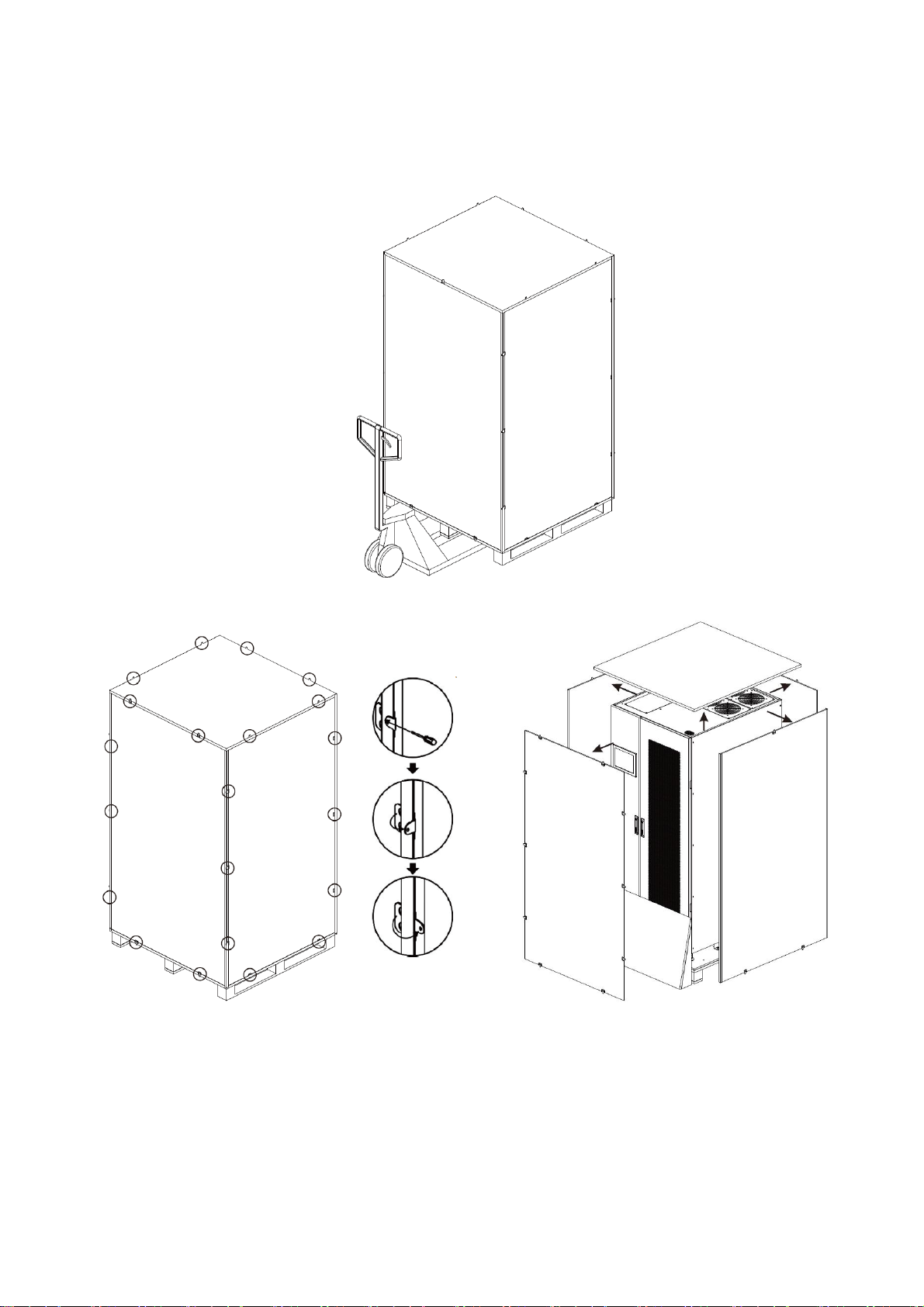
2.3 Unpacking ....................................................................................................................5
2.4 Moving the Cabinet .......................................................................................................7
2.5 Types of UPS Cabinet .................................................................................................. 10
2.6 Exterior ...................................................................................................................... 11
2.7 Internal Mechanisms ................................................................................................... 13
2.8 Control Panel.............................................................................................................. 19
2.9 Introduction of Modules .............................................................................................. 20
2.10 Power Cable ............................................................................................................. 23
2.11 Wiring ...................................................................................................................... 25
2.12 Power Module Installation.......................................................................................... 28
3. Operation Mode and UPS Operation............................................................................... 30
3.1 Block diagram of UPS.................................................................................................. 30
3.2 Operation Mode .......................................................................................................... 32
3.3 UPS Operation ............................................................................................................ 36
4. Control Panel and Display Description................................................................................ 48
4.1 Introduction ............................................................................................................... 48
4.2 Screen Description ...................................................................................................... 49
4.3 Alarm List................................................................................................................... 69
4.4 History Record............................................................................................................ 71
5. Interface and Communication ........................................................................................... 72
5.1 Dry Contact Port ......................................................................................................... 72
5.2 Extra Comm. Slot........................................................................................................ 74
5.3 Local Communication Ports –RS232 & USB .................................................................. 74
5.4 SNMP Slot .................................................................................................................. 74
6. Troubleshooting ............................................................................................................... 75
7. Service ............................................................................................................................ 77
7.1
Replacement Procedures Of Power Module ................................................................... 77
7.2 Replacement Procedures Of STS Module....................................................................... 77
7.3 Replacement Procedures Of Air Filter ........................................................................... 78
8. Specifications................................................................................................................... 79
8.1 Conformity And Standards....................................................................................... 79
8.2 Environmental Characteristics.................................................................................. 79
8.3 Mechanical Characteristics....................................................................................... 79
8.4 Electrical Characteristics (Input Rectifier) ..................................................................... 80
8.5 Electrical Characteristics (Intermediate DC Circuit).................................................... 81
8.6 Electrical Characteristics (Inverter Output) ............................................................... 81
8.7 Electrical Characteristics (Bypass Mains Input) ......................................................... 82

1
1. Safety
1.1 Important Safety Instructions
This UPS contains LETHAL VOLTAGES. All repairs and service must be performed by AUTHORIZED
SERVICE PERSONNEL ONLY. There are NO USER SERVICEABLE PARTS inside the UPS.
WARNING:
⚫The UPS designed for commercial and industrial purpose, it is forbidden to apply for any life
sustainment and support.
⚫The UPS system contains its own energy source. The output terminals may carry live voltage
even when UPS is disconnected to an AC source.
⚫To reduce the risk of fire or electrical shock, UPS installation shall be in a controlled room
where temperature and humidity are monitored. Ambient temperature must not exceed 40°C.
The system is only for indoor use.
⚫Ensure all power is disconnected before installation or service.
⚫Service and maintenance should be performed by qualified personnel only.
1.2 EMC
WARNING: This is a product for commercial and industrial application in the second environment
- installation restrictions or additional measures may be needed to prevent disturbances.
WARNING:This equipment has been tested and found to comply with the limits for a Class A
digital device, pursuant to part 15 of the FCC Rules. These limits are designed to provide
reasonable protection against harmful interference when the equipment is operated in a
commercial environment. This equipment generates, uses, and can radiate radio frequency energy
and, if not installed and used in accordance with the instruction manual, may cause harmful
interference to radio communications. Operation of this equipment in a residential area is likely to
cause harmful interference in which case the user will be required to correct the interference at his
own expense
1.3 Installation information
WARNING:
⚫Installation must be performed by qualified personnel only.
⚫The cabinets must be installed on a level floor suitable for computer or electronic equipment.
⚫The UPS cabinet is heavy. If unloading instructions are not closely followed, the cabinet may
Before working on this circuit
-Isolate Uninterruptible Power
System (UPS)
-Then check for Hazardous
Voltage between all terminals
including the protective earth.
Risk of Voltage Backfeed
The isolation device must be able to carry the UPS input current.

2
cause serious injury.
⚫Do not tilt the cabinets more than 10 degrees.
⚫Before applying electrical power to the UPS, make sure the Ground conductor is properly
installed.
⚫Installation and Wiring must be performed in accordance with the local electrical laws and
regulations.
⚫The disconnection device should be chosen based on the input current and should break line
conductors –three poles for three phases.

3
1.4 Maintenance
WARNING:
⚫Only qualified service personnel should perform the battery installation.
⚫The following PRECAUTIONS should be observed
(1.) Remove watches, rings, or other metal objects.
(2.) Use tools with insulated handles.
(3.) Wear rubber gloves and boots.
(4.) Do not lay tools or metal parts on top of batteries or battery cabinets.
(5.) Disconnect the charging source prior to connecting or disconnecting terminal.
(6.) Check if the battery is inadvertently grounded. If it is, remove the source of grounding.
Contacting with any part of the ground might result in electrical shock. The likelihood of
such shock can be prevented if such grounds are removed during installation and
maintenance.
⚫UPS is designed to supply power even when disconnected from the utility power. Disconnect
all input AC and DC power before removing protective covers or accessing internal
components.
⚫Do not disconnect the batteries while the UPS is in Battery mode.
⚫Disconnect the charging source prior to connecting or disconnecting terminals.
⚫Batteries can result in a risk of electrical shock or burn from high short circuit current.
⚫When replacing batteries, use the same type and number of batteries.
⚫Do not open or mutilate the battery. Release electrolyte is harmful to the skin and eyes, and
may be toxic.
1.5 Recycling the used battery
WARNING:
⚫Do not dispose of the battery in a fire. Battery may explode. Proper disposal of battery is
required. Refer to your local codes for disposal requirements.
⚫Do not open or mutilate the battery. Released electrolyte is harmful to the skin and eyes. It
may be toxic.
⚫Do not discard the UPS or the UPS batteries in the trash. This product contains sealed,
lead-acid batteries and must be disposed properly. For more information, contact your local
recycling/reuse or hazardous waste center.
⚫Do not discard waste electrical or electronic equipment (WEEE) in the trash. For proper
disposal, contact your local recycling/reuse or hazardous waste center.
CAUTION:
RISK OF EXPLOSION IF BATTERY IS REPLACED BY AN INCORRECT TYPE. DISPOSE OF USED
BATTERIES ACCORDING TO THE INSTRUCTION.

4
2. Installation
2.1 Initial Inspection
1. Visually examine if there is any damage inside and outside of packages from transportation. If
any damage, report it to the carrier immediately.
2. Verify the product label and confirm the consistency of the equipment.
3. If the equipment needs to be returned, carefully repack the equipment by using the original
packing material.
2.2 Installation Environment
1. The UPS is designed for indoor use only and should be located in a clean environment with
adequate ventilation to keep the environmental parameters within the required specification.
2. Make sure that transportation routes (e.g. corridor, door gate, elevator, etc.) and installation
area can accommodate and bear the weight of the UPS, the external battery cabinet and
handling equipment.
3. The UPS uses forced convection cooling by internal fans. Cooling air enters the module
through ventilation grills located at the front of the cabinet and exhausted through grills
located in the top rear of the cabinet. Please do not block the ventilation holes.
4. Ensure that the installation area is spacious for maintenance and ventilation.
5. Keep the temperature of installation area below 40°C and humidity within 90%. The highest
operating altitude is 1000 meters above sea level.
6. If necessary, install a system of room extractor fans to avoid formation of room temperature.
Air filters are necessary if the UPS is operated in a dusty environment.
7. It is recommended that you parallel the external battery cabinets to the UPS. The following
instructions of clearances are suggested:
⚫Keep a clearance of 100cm from the top of the UPS for maintenance, wiring and
ventilation.
⚫Keep a clearance of 36”from the front of the UPS and the external battery cabinets for
maintenance and ventilation.
8. For safety concerns, we suggest that you shall:
⚫Equip the space with CO2 or dry powder fire extinguishers near the installation area.
⚫Install the UPS in an area where the walls, floors and ceilings were constructed by
fireproof materials.
9. Do not allow unauthorized personnel to enter the installation area. Assign specific personnel
to keep the UPS key.

5
2.3 Unpacking
1. Use a forklift to move the product to installed area. Refer to Figure 2-1. Please make sure the
bearing capacity of forklift is sufficient.
2. Please follow the orders in Figure 2-2 to remove carton and foam.
Figure 2-1
]
Figure 2-2

6
3. Put a ramp in the front of the cabinet. Refer to Figure 2-3.
Figure 2-3
4. Remove 2 fixing cabinet plates and loosen leveling feet by rotating them counterclockwise.
Then, move the cabinet from the pallet. Refer to Figure 2-4.
5. To fix the cabinet in position, simply rotate leveling feet clockwise. Refer to Figure 2-5.
Figure 2-4
Figure 2-5

7
2.4 Moving the Cabinet
The UPS is fixed on the pallet with 2 fixing cabinet plates. When removing it, pay attention to
the movement of the casters to avoid accidents.
The cabinet can be pushed forward or backward only. Pushing it sideward is not allowed.
When pushing the cabinet, pay attention not to overturn it as the gravity center is high.
1. If you need to move the UPS over a long distance, please use appropriate equipment like a
forklift. Do not use the UPS casters to move over a long distance.
2. After the UPS has been removed from the pallet to ground, we suggest that at least three
people move the UPS to the installation area. One person holds a lateral side of the UPS with
hands, another holds the other lateral side of the UPS with hands, and the other person pushes
the UPS either from the front side or from the back side to the installation area and avoid
tipping the UPS.
3. The casters are designed to move on level ground. Do not move the UPS on an uneven surface.
This might cause damage to the casters. Toppling the UPS could also damage the unit.
4. Ensure that the weight of UPS is within the designated bearing capacity of any handling
equipment.
5. At the bottom of the UPS, the four casters help you to move the UPS to a designated area.
Before you move the UPS, please turn the four leveling feet counterclockwise to raise them off
the ground. This protects the leveling feet from damage when moving the UPS.
6. Secure the cabinet firmly to the ground with the fixing cabinet plate. Refer to Figure 2-6.
Figure 2-6

8
7. Install the optional Slim Bypass Cabinet
Step 1: Remove one side of case cover from the bypass cabinet and the UPS cabinet.
Slim bypass cabinet UPS cabinet
(optional)
Step 2: Remove bus bars of input 1 and bypass input on main cabinet. Remove all terminal
retaining plates on slim bypass cabinet.
Slim bypass cabinet UPS cabinet
(optional)

9
Step 3: Align slim bypass cabinet and UPS cabinet and assmble both of cabinets together with
supplied M10 screws, washers and spring washers. Fix long plate (supplied in slim bypass
cabinet package) on the top of two cabinets.
Slim bypass cabinet UPS cabinet
(optional)
Step 4: Use supplied 9 sets of bus bars to connect input, bypass and output terminals of Slim
bypass cabinet and UPS cabinet.
Slim bypass cabinet Main cabinet
(optional)
Slim bypass
cabinet
UPS
cabinet

10
2.5 Types of UPS Cabinet
The UPS cabinets don’t have an internal battery module compartment. The battery has to be
connected externally.
Please consider the external battery space and wiring gauge for installation.
X90-5S and 10S Series
Model
X90-SMB350 / X90-ENC5S
X90-SMB700 / X90-ENC10S
Photo
Cabinet Height
2000mm
2000mm
Switch Unit
3
3
STS
1
1
Max. Power Module
5
10
Max Power
350kVA
700kVA

11
2.6 Exterior
In the front of the UPS, there are control interface (LCD Panel) and door lock.
The side panels are removable. The casters at the bottom of the UPS cabinet can be used to move
over short distances. There are four leveling feet to fix and stabilize the UPS cabinet on the ground.
Refer to Figure 2-7.
Inside the cabinet, there are STS Module and Power Module slots. Breakers are located in the
optional Bypass Cabinet. All wiring terminals are located in the front left of cabinet.
Figure 2-7 Exterior

12
2.6.1 Mechanical Data
Dimensions
UPS cabinet
Width
Depth
Height
X90-SMB350 /
X90-ENC5S
11.8”/31.5”
50”
78.7”
X90-SMB700 /
X90-ENC10S
17.7”/35.4”
50”
78.7”
Figure 2-8 Dimensions

13
2.6.2 Front View
Unlock and open the front door and you will see the Main Breaker (Q1), Maintenance Breaker (Q2),
Output Breaker (Q3) in the optional bypass switch, and STS Module and Power Module slots.
X90-SMB350 / X90-ENC5S X90-SMB700 / X90-ENC10S
Figure 2-9 Front View
2.6.3 Rear View
Unlock and open the rear door and you will see the rear panel of UPS.
2.7 Internal Mechanisms
2.7.1 Breakers
After opening the front door, there are three breakers, Main Breaker (Q1), Maintenance Breaker
(Q2) and Output Breaker (Q3) in 350K/700K cabinet.

14
X90-SMB350 X90-SMB700
Figure 2-11 Switch (front view)
2.7.2 Wiring Terminal Blocks
Open the UPS’s back doors and you will see the wiring terminal block. For UPS cabinet wiring,
please refer to Figure 2-13.
No.
Item
Function
Description
Output Block
Connects the critical loads
Includes R, S, T terminals.
Bypass Input Block
Connects bypass AC source
Includes R, S, T terminals.
Main Input Block
Connects main AC source
Includes R, S, T terminals.
For UPS Grounding
For UPS grounding
Includes one grounding terminal.
Battery Input Block
Connects an external battery
cabinet
Includes
Positive (+), Negative (-) and
Neutral (N) terminals.

15
X90-ENC5S

16
X90 SMB350

17
X90-ENC10S
X90 SMB700
Figure 2-13 Terminal Blocks

18
2.7.3 EMI solution
To meet EMI requirements, please add EMI core as Figure 2-14.
Figure 2-14 EMI core
Other manuals for X90-5S
1
Table of contents
Other Xtreme UPS manuals