Copyright ©2018, 2020, 2021, ASSA ABLOY Access and Egress Hardware Group, Inc. All rights reserved. Reproduction in
whole or in part without the express written permission of ASSA ABLOY Access and Egress Hardware Group, Inc. is prohibited
9
8094700010000 05/21
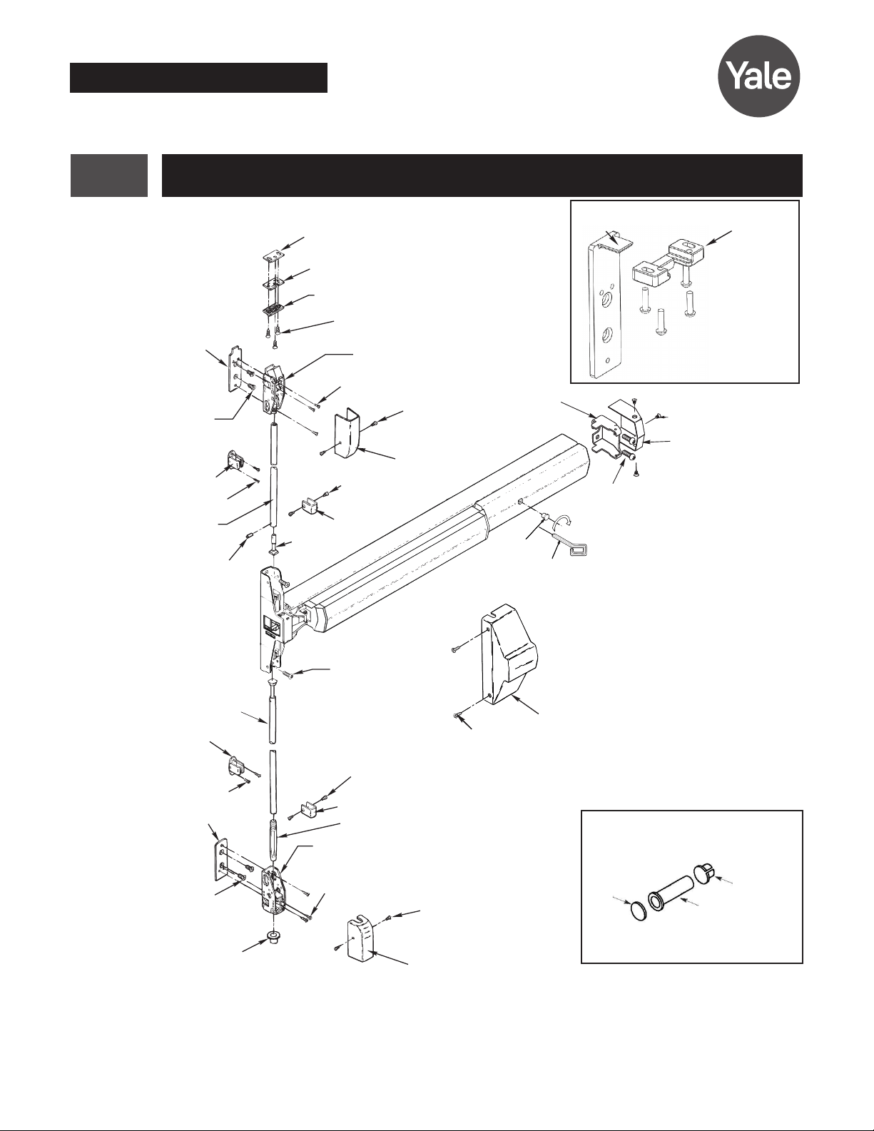
Surface Vertical Rod Exit Device Series
Installation Instructions
7110(F) and 7170(F) (LBR)
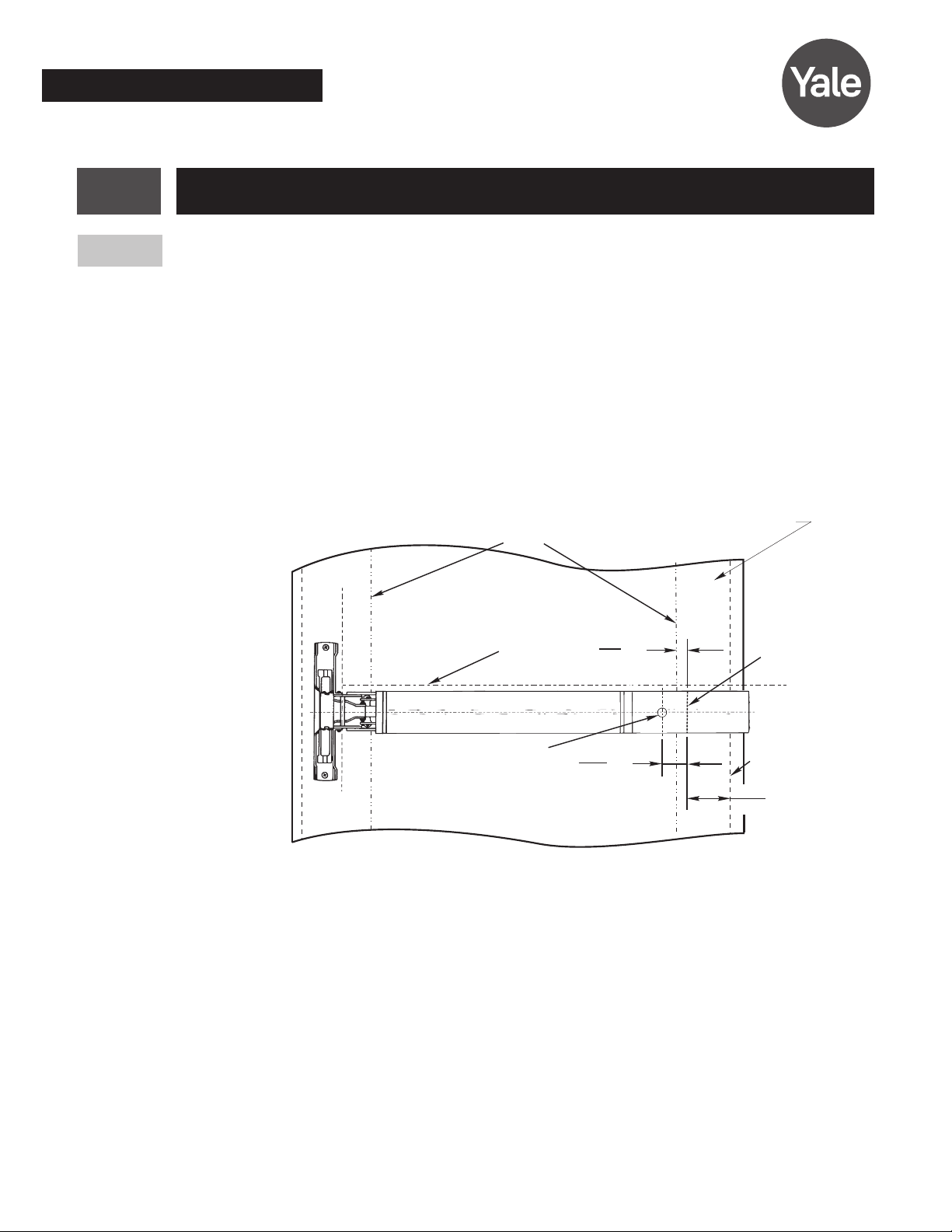
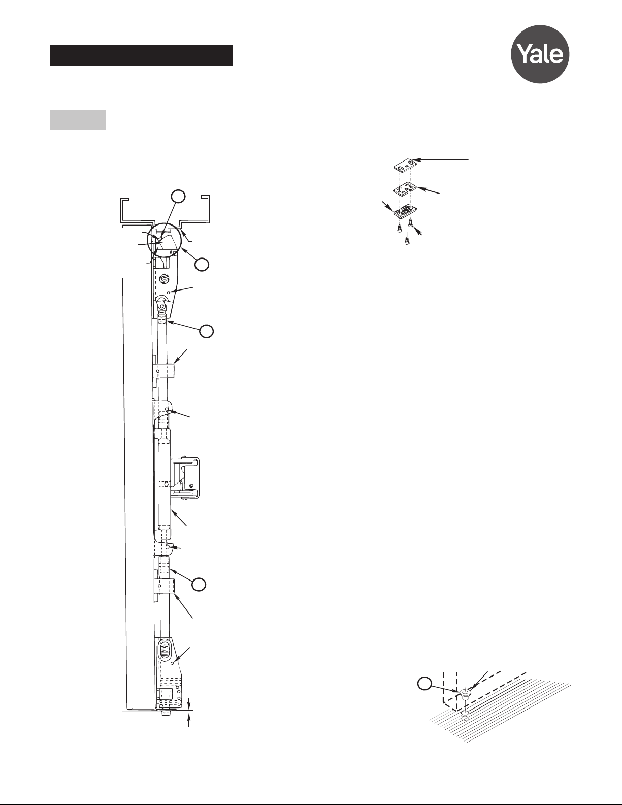
B2
(Press in place)
Bolt
Engagement
Frame
Stop
Rod Guide
A2
A
3/8"
(10)
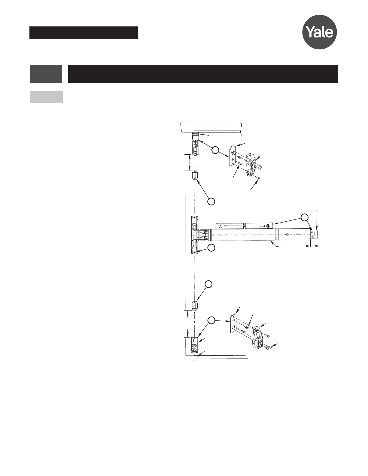
Cover
Screw
Hole
Cover
Screw
Hole
Cover
Screw
Hole
Cover
Screw
Hole
A1
B
Rod Guide
Slide
Roller
Bolt
Tripping
Lever
gComplete Installation
Shim
(2) Supplied (Start With One)
Strike Plate
(Ridges Face Down)
791 Strike
(3) 10-24 x 3/4" (19mm) PFHMS
Top Strike Detail
A. Install Top Rod and 791 Strike
1. Thread Top Rod Assembly onto Top Latch. Lift rod to fully retract Top
Latchbolt. Depress Pushpad and hold depressed. Adjust top rod length
until Rod Connector seats into the Slide Assembly in latch case.
Note: For 7170 devices, skip section (2a) and 2(b). See the installation
instructions for the 726 strike on page 9.
2a. Position the Top Strike Roller between the Tripping Lever and the Bolt on
the Top Latch. Verify hole positions and prepare holes per Installation
Instruction Template.
2b. Install Top Strike and Strike Plate using (2) #1024 x 3/4” (19mm) PFHMS
thru outer slots. Adjust and shim strike as needed for zero door rattle. Add
third screw (#1024 x 3/4” (19mm) PFHMS) after final adjustments.
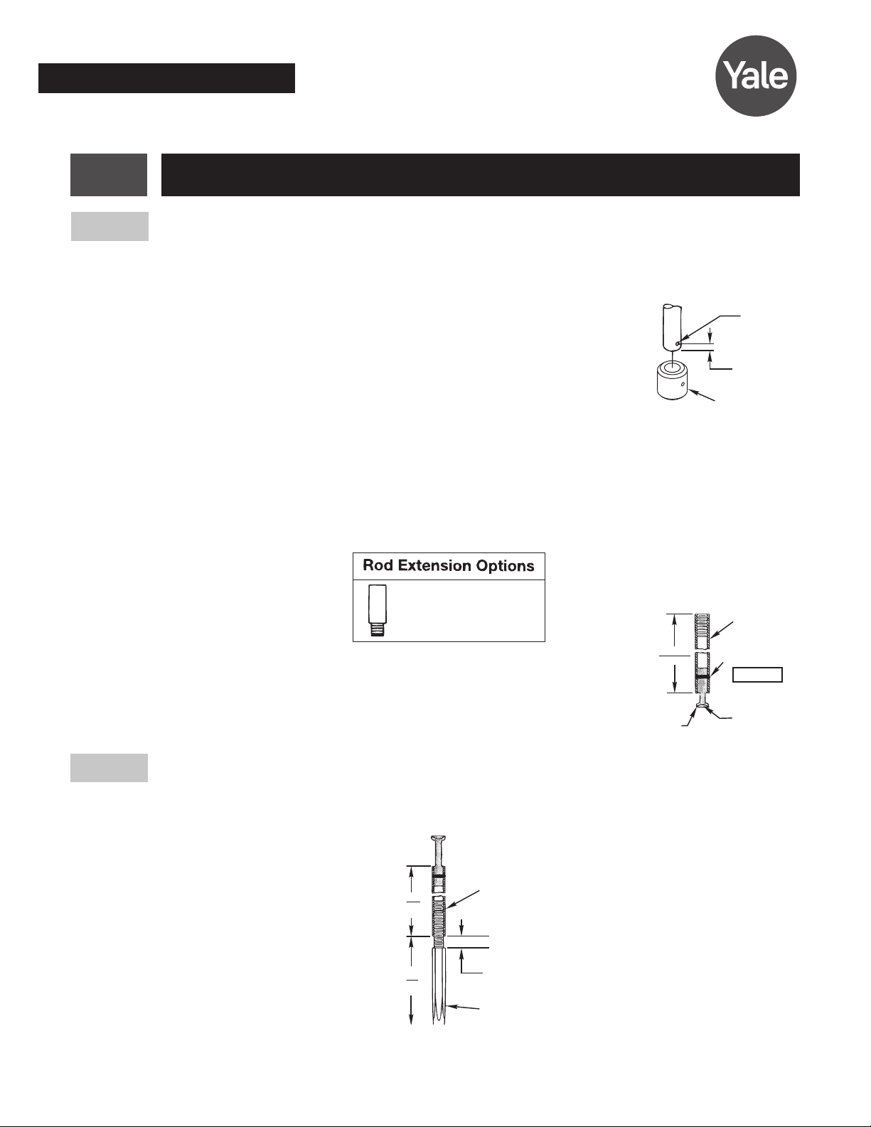
3. If Top Bolt does not remain retracted when door is opened, Top Rod is too
short. Pull rod out of the guide and the slide then rotate rod to increase
length. Upper Bolt should retract flat.
4. If upper latch will not deadlock, Top rod is too long. Pull rod out of the
guide and the slide and rotate to decrease length.
* If 7170 LBR, skip section B.
B. Install Lower Rod and 790 Strike
1. With door open, actuate Pushpad to retract upper latch. Hang Lower rod
from bottom of Slide and adjust bolt so that it clears the finished floor by
1/4”.
2. Verify location of pipe strike template. Prepare the strike hole and install
the pipe strike. Set in place with appropriate bonding material.
3. With the door open, actuate pushpadt o retract upper latch. Adjust bolt
height by pulling the rod out of the guide and slide and rotating until the
bolt clears the pipe strike by 1/8”.
C. Test device action by Touchbar, by Trim, by Dogging.
D. Install covers.
Note: Bottom Bolt will retract to
1/8” (3mm) above Floor Strike.
Floor covering in the door path
must be laid out accordingly.