Zapi EPS-AC0 User manual

ELECTRONIC • OLEODYNAMIC • INDUSTRIAL
EQUIPMENTS CONSTRUCTION
Via Parma, 59 – 42028 – POVIGLIO (RE) – ITALY
Tel +39 0522 960050 (r.a.) – Fax +39 0522 960259
EN
User Manual
EPS-AC0

Page - 2/95 AEMZP0BA - EPS-AC0 - User Manual
Copyright © 1975-2006 Zapi S.p.A.
All rights reserved
The contents of this publication is a ZAPI S.p.A. property; all related authorizations are covered by
Copyright. Any partial or total reproduction is prohibited.
Under no circumstances will Zapi S.p.A. be held responsible to third parties for damage caused by
the improper use of the present publication and of the device/devices described in it.
Zapi spa reserves the right to make changes or improvements to its products at any time and
without notice.
The present publication reflects the characteristics of the product described at the moment of
distribution. The publication therefore does not reflect any changes in the characteristics of the
product as a result of updating.
is a registered trademark property of Zapi S.p.A.
NOTES LEGEND
4The symbol aboard is used inside this publication to indicate an annotation or a
suggestion you should pay attention.
UThe symbol aboard is used inside this publication to indicate an action or a
characteristic very important as for security. Pay special attention to the
annotations pointed out with this symbol.

AEMZP0BA - EPS-AC0 - User Manual Page - 3/95
Contents
1INTRODUCTION...................................................................................................................6
2SPECIFICATION...................................................................................................................7
2.1 Technical specifications .............................................................................................7
2.2 Block diagram.............................................................................................................7
2.3 Electrical specifications ..............................................................................................7
2.4 Mechanical specifications...........................................................................................8
2.4.1 Basic release................................................................................................8
3FUNCTIONS OF THE EPS-AC0...........................................................................................9
3.1 Manual Mode Steering ...............................................................................................9
3.2 Automatic Centering.................................................................................................10
3.3 Operational features.................................................................................................11
3.4 Diagnosis..................................................................................................................11
4SYSTEM COMPONENTS...................................................................................................12
4.1 Steering Motor..........................................................................................................12
4.2 Gear Box and total reduction ratio............................................................................12
4.3 Eps-ac0 controller ....................................................................................................12
4.3.1 Eps-ac0 PCB..............................................................................................13
4.4 Sensor in the steering handle...................................................................................14
4.4.1 Stepper motor.............................................................................................14
4.4.2 Twin pot......................................................................................................14
4.5 Feedback sensors....................................................................................................15
4.5.1 Encoder in the motor shaft and a Feedback Potentiometer.......................15
4.5.2 Encoder in the motor shaft and one (two) toggle switch(es) ......................17
4.5.3 Feedback Encoder .....................................................................................18
5AUTC MODE.......................................................................................................................21
6CONNECTING DIAGRAMS................................................................................................22
6.1 Power Connecting Diagram .....................................................................................22
6.2 EPS-AC0 Stepper Motor diagram ............................................................................23
6.3 EPS-AC0 Twin pot diagram......................................................................................24
7CONNECTIONS: SUGGESTIONS AND CAUTIONS.........................................................25
7.1 Stepper Motor connections ......................................................................................25
7.2 Twin pot connections................................................................................................25
7.3 Encoder connections................................................................................................25
7.4 Feedback pot connections .......................................................................................25
7.5 Digital Inputs connections ........................................................................................26
7.6 Safety contacts.........................................................................................................27
7.7 Motor thermal sensor connections...........................................................................27
8INSTALLATION: SUGGESTIONS AND CAUTIONS.........................................................28
8.1 Thermal consideration..............................................................................................28
8.1.1 Controller with Base Plate..........................................................................28
8.1.2 Controller with finned Heatsink...................................................................28
8.2 General suggestion ..................................................................................................29
8.3 Connection cables....................................................................................................29
8.4 Fuses........................................................................................................................30
8.5 Contactors................................................................................................................30
8.6 Installation of a CAN Communication System..........................................................31
8.7 Wiring: I/O connections ............................................................................................33

Page - 4/95 AEMZP0BA - EPS-AC0 - User Manual
8.8 Safety features .........................................................................................................34
8.9 EMC .........................................................................................................................34
8.9.1 Emission.....................................................................................................35
8.9.2 Electromagnetic Immunity ..........................................................................35
8.9.3 ESD............................................................................................................35
8.10 Fighting the dither.....................................................................................................36
9DESCRIPTION OF THE CONNECTORS ...........................................................................38
9.1 Connectors of the logic.............................................................................................39
9.1.1 CNA connector...........................................................................................39
9.1.2 CNB connector...........................................................................................39
9.1.3 CNC connector...........................................................................................40
9.2 Description of power connections ............................................................................41
10 INSTALLATION PROCEDURE ..........................................................................................42
10.1 Twin Pot with Encoder and Feedback pot: one shot installation procedure.............42
10.2 Twin Pot with Encoder, Straight Ahead Switch and Feedback pot: one shot installation
procedure.................................................................................................................43
10.3 Stepper Motor with Encoder and Feedback pot: one shot installation procedure....45
10.4 Stepper Motor with Encoder and Toggle Switch(es): one shot installation procedure46
11 SETTING THE EPS-AC0 ....................................................................................................49
11.1 Complete set-up description.....................................................................................49
11.1.1 Stepper Motor only.....................................................................................49
11.1.2 Stepper Motor & AUTC...............................................................................49
11.1.3 RTC (Twin Pot) only...................................................................................49
11.1.4 RTC & AUTC..............................................................................................50
11.2 Quick set-up .............................................................................................................50
11.2.1 Stepper Motor only.....................................................................................50
11.2.2 Stepper Motor & AUTC...............................................................................51
11.2.3 RTC only or RTC & AUTC..........................................................................51
12 PROGRAMMAING & ADJUSTMENTS USING DIGITAL CONSOLE................................52
12.1 Adjustments via console...........................................................................................52
12.2 Description of console (hand set) & connection.......................................................52
12.3 Description of standard console menu.....................................................................53
12.3.1 Stepper motor with Encoder and Feedback pot.........................................54
12.3.2 RTC with Encoder and Feedback pot.........................................................55
12.3.3 Stepper motor with Encoder and Toggle switch(es)...................................56
12.4 Function configuration..............................................................................................57
12.4.1 Config menu “SET OPTIONS” functions list...............................................58
12.4.2 Config menu “ADJUSTMENTS” functions list ............................................62
12.4.3 Config menu “SET MODEL” functions list..................................................65
12.4.4 Main menu “PARAMETER CHANGE” functions list...................................68
12.4.5 Zapi menu “HARDWARE SETTINGS” functions list ..................................75
12.4.6 Zapi menu “SPECIAL ADJUSTMENT” functions list..................................76
12.4.7 Main menu “TESTER” functions list ...........................................................78
13 OTHER FUNCTIONS..........................................................................................................82
13.1 Acquiring the Motor resistance.................................................................................82
13.2 Alignment at the rest position...................................................................................82
13.3 Straight ahead steering numbness...........................................................................82
13.4 Special Debugging and Troubleshooting system.....................................................83
14 EPS-AC0 ALARMS LIST....................................................................................................84

AEMZP0BA - EPS-AC0 - User Manual Page - 5/95
14.1 Main menu “ALARMS” list........................................................................................84
14.1.1 One Blink Alarms........................................................................................84
14.1.2 Two Blinks Alarms......................................................................................86
14.1.3 Three Blinks Alarms ...................................................................................87
14.1.4 Four Blinks Alarms .....................................................................................90
14.1.5 Five Blinks Alarms......................................................................................91
14.1.6 Six Blinks Alarms........................................................................................91
14.1.7 Thirty-two Blinks Alarms.............................................................................92
14.1.8 No Blink Alarms (Warning).........................................................................92
14.2 CAN BUS “ALARMS” List.........................................................................................93
15 RECOMMENDED SPARE PARTS.....................................................................................94
16 PERIODIC MAINTENANCE TO BE REPEATED AT TIMES INDICATED.........................95
16.1 Testing the faulty detection circuitry.........................................................................95
APPROVAL SIGNS
COMPANY FUNCTION INIZIALS SIGNS
PROJECT MANAGER MI
TECHNICAL ELECTRONIC
MANAGER VISA PP
SALES MANAGER VISA PN
Publication N°: AEMZP0BA
Edition: May 2006

Page - 6/95 AEMZP0BA - EPS-AC0 - User Manual
1 INTRODUCTION
This equipment (Eps-ac0: AC0 Electrical Power Steering) may perform two steer by
wire functions on a truck:
1) manually controlled power steering
2) automatic centering (AUTC).
Manually controlled steering may use either a stepper motor (used as a
tachogenerator) or a twin pot fixed to the steering wheel.
Feedback sensors are mandatory to close the loop when an automatic function is
required (Automatic Centering).
Feedback sensors are mandatory to close the loop in manual mode if a twin pot is
mounted on the steering wheel.
Feedback sensors are strongly suggested (to improve safety) in manual mode if a
stepper motor is mounted on the steering wheel (open loop).
The feedback sensor may be an incremental encoder on the steering motor shaft in
combination with one straight-ahead switch. A second switch may be adopted,
together with the first one, in the 90 degrees position to improve safety. Besides a
feedback potentiometer may be chosen in alternative to the straight-ahead switch.
The eps-ac0 runs an inexpensive, robust and maintenance free three phases
AC induction motor. Also, our patented system makes possible to use a very low-
resolution encoder (4 pulses/rev are more than enough) mounted on the
steering motor shaft.
The on board CAN interface makes the communication exchange between our
eps-ac0 and other units in the truck rapid and simple. Via CAN it is possible to
enhance the steering performances with additional functions like: steer sensitivity
changes with the traction speed, traction speed modulation vs. the steered angle,
via CAN automatic centering request and so on.
Configuration options, steering adjustment, measurement functions, and
troubleshooting operations are integrally supported by the ZAPI hand held
controller equipped with Eprom release number CKULTRA ZP3.01 or subsequent.
Having two microprocessors provides improved safety and operation. The first
microprocessor performs operations and a second one executes supervisor
functions. Both the aboard microprocessors are CAN BUS connected, as
consequence the eps-ac0 may receive a remote steering command directly via
CAN fulfilling the norm (the redundant check of the steering command
complies with the Category #3 requirement).
The microprocessors combined with the ZAPI hand held controller make servicing
easy and direct, reducing adjustment and troubleshooting time. Increased steering
motor performance and reduced noise levels are achieved by using MOSFET
technology.
The reference SW release for this manual is ZP0.70.

AEMZP0BA - EPS-AC0 - User Manual Page - 7/95
2 SPECIFICATION
2.1 Technical specifications
Steering controller for AC asynchronous 3-phase motors
Digital Control using Two Microprocessors
Can-Bus interface
Both microprocessors Can Bus connected
Encoder Interface
Stepper Motor or Twin Pot Interface
Analog Feedback pot interface (1024 steps resolution)
Analog KTY84-130 thermal sensor input
Analog input with 1024 steps resolution (one input)
Analog input with 4096 steps resolution (one input)
Two digital inputs
Double Safety Relay inside
Operating frequency:.............................................8 kHz with center aligned PWM
External temperature range:.............................................................-30 °C ÷ 40 °C
Maximum inverter temperature:......................................................................75 °C
Environment protection:....................................................................................IP54
2.2 Block diagram
Figure 2-1
2.3 Electrical specifications
Battery Voltage:.......................................................................................24 V-36 V
Maximum current (24 V-36 V):..................................................... 50 A (RMS) for 2'
Logic Supply current:..............................................................max 200 mA @ 24 V

Page - 8/95 AEMZP0BA - EPS-AC0 - User Manual
Minimum Input (key) Supply Voltage after start-up:..........................................12 V
2.4 Mechanical specifications
2.4.1 Basic release
It has Molex Minifit connector with international protection IP54.
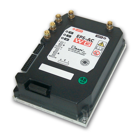
EPS-AC0
Figure 2–2

AEMZP0BA - EPS-AC0 - User Manual Page - 9/95
3 FUNCTIONS OF THE EPS-AC0
The eps-ac0 controls a steer system for warehouse trucks. It executes the following
functions:
1) Manual mode steering
2) Automatic Centering.
3.1 Manual Mode Steering
Manual mode steering requires a command sensor in the hand wheel. The hand
wheel may be of two types:
1) Multiturn steering wheel without end-strokes.
2) Handlebar, tiller or joy-stick with end-strokes to limit the angle.
With a Multiturn steering wheel, the sensor in the hand-wheel shall be a stepper
motor used as a tacho-generator (see Figure 3-1). Then the control will turn the
steering motor moving at a speed proportional to the stepper motor speed (Open
loop Mode).
Stepper Motor
Figure 3-1
With a Handlebar (tiller or joy-stick), the sensor in the hand-wheel will be a twin pot
(see Figure 3-2 below). Then the system works as a position control loop with a rigid
correspondence between the angle of the handlebar and the angle of the steered
wheel (Closed Loop Mode). In this case a feedback sensor on the steered wheel is
mandatory.

Page - 10/95 AEMZP0BA - EPS-AC0 - User Manual
Twin Pot
Figure 3–2
The same controller may work either with the stepper motor or the twin pot without
hardware modification. It is just enough to set the SYSTEM CONFIG to the correct
value (see 12.4.3.1).
3.2 Automatic Centering
Automatic Centering turns the steered wheel straight ahead to keep the steer
aligned meanwhile travelling inside an aisle between rails (see Figure 3-3).
Figure 3–3

AEMZP0BA - EPS-AC0 - User Manual Page - 11/95
3.3 Operational features
A list of eps-ac0 operational features follows below:
1) Static sensitivity boost in open loop (steering sensitivity increases for a slow
moving steering wheel).
2) Static numbness in closed loop (steering sensitivity decreases for handle steer
close to the straight-ahead direction).
3) Dynamic Numbness in open loop (steering sensitivity reduces when the truck
speed increases).
4) Dynamic Numbness on request in closed loop (steering sensitivity reduces
when the truck speed increases).
5) Truck speed reduces when the steering angle increases.
6) Alignment at the rest position in open loop application (to avoid the drift of the
steered wheel when travelling with released steering wheel).
7) Embedded PID algorithm for closed loop application (Twin Pot).
8) Embedded PID algorithm for automatic functions (AUTC).
9) Special Debugging & Troubleshooting system makes easier the fault catching.
10) Possibility to run in a stand-alone (not CAN Bus supported) configuration.
11) Motor control may be performed with or without encoder. Default choice is
without encoder. The adoption of a cheap and low-resolution encoder is
possible.
12) Redundant processing (two microprocessors aboard) fulfils the Category #3
requirement including the set-point comes via CAN Bus from a remote unit.
13) Redundant set point and feedback sensors fulfil the Category #3 requirement.
14) Redundant safety-contact fulfils the Category #3 requirement in a stand-alone
configuration.
3.4 Diagnosis
According to EN1175, most of the diagnoses deenergize steer and traction in less
then 100 msec. Few secondary alarm conditions require longer time for detection.
They too deenergize steer and traction: it is better to have delayed alarm than no
alarm at all.
Diagnosis is provided in two ways. The digital console can be used, which gives a
detailed information about the failure; the failure code is also sent on the Can-Bus.

Page - 12/95 AEMZP0BA - EPS-AC0 - User Manual
4 SYSTEM COMPONENTS
The eps-ac0 controller needs some external parts in order to work. The following list
describes the complete equipment.
4.1 Steering Motor
The steering system includes a three phase AC induction motor. The motor rated
power (S2-1h) changes with the truck type. As a thumb rule:
1) A low level OP asks a motor with rated power higher than 250 W @ 3000 rpm.
2) A reach truck asks a motor with rated power higher than 400 W @ 3000 rpm.
Obviously the above list is only a rough information: the motor should be chosen
from time to time according the rated torque and speed customer’s specifications.
4.2 Gear Box and total reduction ratio
Normally, the total reduction ratio between steered wheel and motor shaft should be
close to 1:200. Normally it is split into:
1) Gear box ratio close to 1:50.
2) External gears ratio close to 1:4.
The maximum continuous output torque requirement changes with the truck type. As
a thumb rule and in the worst case (stalled steer):
1) A low level OP asks a maximum torque of about 250 Nm on the wheel to steer.
2) A reach truck asks a maximum torque of about 600 Nm on the wheel to steer.
Obviously the above list is only a rough information: the reduction ratio together with
the gear-box should be chosen from time to time according the customer’s
specifications.
4.3 Eps-ac0 controller
It consists of a control unit on a PCB marked AEMZPA0B (see Figure 4.1) which
operates the AC asynchronous motor for manual and centering mode. Eps-ac0
works with 24 to 36 V battery and a maximum current up to 50 Aac.
It has flash memory aboard and it is possible to boot the SW in the Master
microprocessor through both, Serial hand set connector (CNC) and via CAN Bus.
For the Slave microprocessor, only via CAN Bus booting is admitted. A Zapi own
program (Flasher) is needed to boot-on the SW.

AEMZP0BA - EPS-AC0 - User Manual Page - 13/95
4.3.1 Eps-ac0 PCB
It has Molex Minifit connector with international protection IP54.
Figure 4–1

Page - 14/95 AEMZP0BA - EPS-AC0 - User Manual
4.4 Sensor in the steering handle
Two configurations are foreseen:
1) No limit, multiturn steering wheel.
2) Tiller, handlebar or joystick arrangement with a limited angle.
Depending by the above choice, there are two different handling:
1) In case of multiturn steering wheel, a stepper motor is used.
2) In case of a handlebar with limited angle, a twin pot is used.
4.4.1 Stepper motor
The stepper motor is used as a tachogenerator. The following part numbers resulted
suited to work with eps-ac0:
1) MINEBEA Type code AA23KM-K227-T20V.
2) JAPAN SERVO Type Code KH56JM2X 1269 DC12V 30 ohm.
They have the same mechanical dimensions (see Figure 4.2 below).
Obviously, the above information states only these parts are suited for the eps-ac0;
no reliability evaluation is given here.
Other sources are possible on request, but must be tested for approval.
Figure 4–2
4.4.2 Twin pot
The Twin pot is a double potentiometer in the same frame. The two potentiometers
inside must have complementary action (i.e. one wiper grows up from zero to Vcc
meanwhile the second wiper reduces from Vcc to zero - see Figure 4-3 below).

AEMZP0BA - EPS-AC0 - User Manual Page - 15/95
Figure 4–3
The following part numbers resulted suited to work with eps-ac0:
1) CONTELEC twin hall sensors 170° Type code VERT-X 2841 417 225.
2) BOURNS twin potentiometers 180° Type Code 6657S-466-502.
3) MCB twin potentiometers 85° Type Code PMR 410 or PMR426.
The CONTELEC is without brushes but drains a high level of current (about 15 mA).
The MCB has the advantage of a spring in the shaft. This spring neutralizes the
dead zone in the tiller side getting a strongly accurate straight-ahead matching;
unfortunately MCB has a limited angle (85°).
Obviously, the above information states only these parts are suited for the eps-ac0;
no reliability evaluation is given here.
Other sources are possible on request, but must be tested for approval.
4.5 Feedback sensors
Feedback sensors are mandatory to close the loop in manual mode if a twin pot is
mounted on the steering wheel.
Feedback sensors are strongly suggested (to improve safety) in manual mode if a
stepper motor is mounted on the steering wheel (open loop).
Eps-ac0 may handle two different configurations for the feedback sensors:
1) Incremental encoder in the motor shaft together with a feedback potentiometer
on the steered wheel.
2) Incremental encoder in the motor shaft together with one (or two) toggle
switch(es) in the straight ahead (and 90 degrees) position of the steered wheel.
On request, in the closed loop application only, eps-ac0 may work also with two
encoders in the motor shaft together with a straight ahead toggle switch.
4.5.1 Encoder in the motor shaft and a Feedback Potentiometer
One possible arrangement for the feedback sensor consists of (see Figure 4-4):
1) Feedback encoder in the motor shaft.
2) Feedback potentiometer on shaft of the steering motor gear box.

Page - 16/95 AEMZP0BA - EPS-AC0 - User Manual
Figure 4–4
4.5.1.1 Feedback potentiometer
The feedback potentiometer is used for both, encoder initialisation and redundancy
on the steered wheel angle measurement. Normally the feedback potentiometer is
multiturn (5 or 10 turns) 5K hybrid technology mounted on the output shaft of the
steering gearbox (see Figure 4-4).

AEMZP0BA - EPS-AC0 - User Manual Page - 17/95
4.5.2 Encoder in the motor shaft and one (two) toggle switch(es)
It consists of (see Figure 4-5):
1) Straight ahead toggle switch on the input CNA#3 and GND.
2) 90 degrees toggle switch on the input CNA#2 and GND.
3) Feedback encoder on the steering motor shaft.
Figure 4–5
4.5.2.1 Straight ahead toggle switch
The straight ahead toggle switch must be of NPN type (i.e. it must connect a minus
battery to CNA#3).
A possible arrangement for the straight-ahead switch (proximity switch) is shown in
Figure 4-6 below. The proximity switch is connected to the truck frame; the Iron
plate rotates together with the steered wheel.
Figure 4-6

Page - 18/95 AEMZP0BA - EPS-AC0 - User Manual
It is handled this way:
1) At key-on, the eps-ac0 turns the steering motor moving in either CW or CCW
side, according to whether the output level from the straight ahead switch is high
or low (in the above sketch a proximity sensor is used as a straight ahead
switch).
2) When the falling edge on the prox switch is detected, the encoder counting is
initialized to 0 and the steered wheel is centered.
3) Then the encoder counting is continuously updated to measure the steered
wheel angle.
At key on, the Iron plate (with the shape shown in Figure 4-6), provides the correct
direction in which the eps-ac0 must turn the steering motor in order the falling edge
on the proximity switch is detected.
An option POT UP SW1 EDGE (see 12.4.1.12) determines the direction where the
steered wheel rotates to seek the straight ahead switch (i.e. it specifies if the steered
wheel at the initial alignment is oriented with the iron plate in its right or left side).
Together with the straight-ahead switch, a second toggle switch could be adopted to
detect when the steered wheel is in the 90 degrees limiting position. This second
toggle switch must be connected to CNA#2 and GND (minus battery).
Iron Plate
Steered wheel
Prox switch
90° Prox switch
Figure 4-7
4.5.3 Feedback Encoder
One big advantage of our eps-ac0 controller is that it can work with a cost-effective
very low-resolution encoder. Our competitors normally need a sensor bearing with
32 or higher pulses/rev; our eps-ac0 works also with a cheap encoder having 4
pulses/rev. That is more than enough for the angle measurement: in fact, with a total
reduction of 1:200 and a 4 pulses/revs resolution, we have 1600 events (encoder
transitions) within 180° of the steered angle. So the angle measurement is
determined with quanta of 180/1600=0.112 degrees. This is possible because our
patent system does not use the encoder for the AC motor control; it works
completely sensorless.
Following this statement, we have developed, together with a Zapi’s partner AC-
motor-brand, a 4 pulses/rev discrete encoder. It is an external device (not integrated
in the ball bearing) mounted in the backside of the motor (see Figure 4.8 below
showing a 300 W AC Motor by “Best Motor” brand). The advantages of this solution
are both, money saving and effective time saving in case of encoder replacement.

AEMZP0BA - EPS-AC0 - User Manual Page - 19/95
Figure 4-8
4Note: On request, it is possible to use the encoder for the motor control. In this
case, the SW must know the encoder resolution together with the poles-pair
number. The encoder resolution and the motor poles pair (the controller can
handle), will be specified in the headline of the handset showing something
like:
EPSAC0S2A ZP0.70
That means:
EPSAC0=Eps-ac0 steering controller
S= Stepper motor
2= poles pair number
A= 32 pulses/rev encoder
ZP= SW release type Zapi
0.70= SW release number 0.70
The command configuration is specified through the first letter after EPSAC0
in the following list:
S= Stepper Motor
P= Twin Pot
C= via CAN Bus Position
D= via CAN Bus Speed
The encoder resolution is given by the last letter before of the SW release in
the following list:

Page - 20/95 AEMZP0BA - EPS-AC0 - User Manual
Q= 4 pulses/rev
S= 6 pulses/rev
W= 16 pulses/rev
A= 32 pulses/rev
K= 48 pulses/rev
B= 64 pulses/rev
The letters to specify the poles pair number and the Encoder resolution are
present only if the SW includes the function for controlling the motor with the
encoder.
Table of contents
Other Zapi Controllers manuals

Zapi
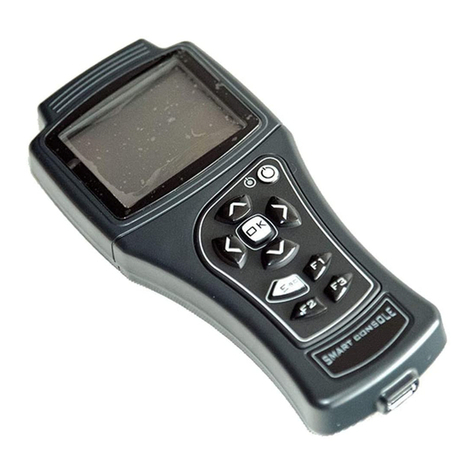
Zapi SMART CONSOLE User manual

Zapi
Zapi COMBI SEM-1 User manual

Zapi
Zapi ZAPIMOS HP 350A User manual

Zapi
Zapi SEM-Zero User manual

Zapi
Zapi COMBI SEM-1 User manual

Zapi
Zapi SMART CONSOLE User manual

Zapi
Zapi ZAPIMOS H2 96V 400A User manual

Zapi
Zapi ADPZP0CC User manual

Zapi
Zapi SMART CONSOLE User manual

Zapi
Zapi SMART CONSOLE User manual