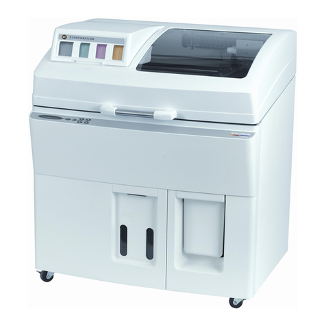
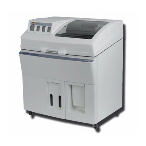
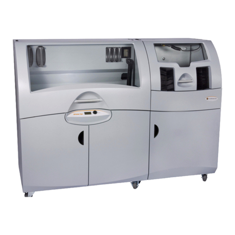
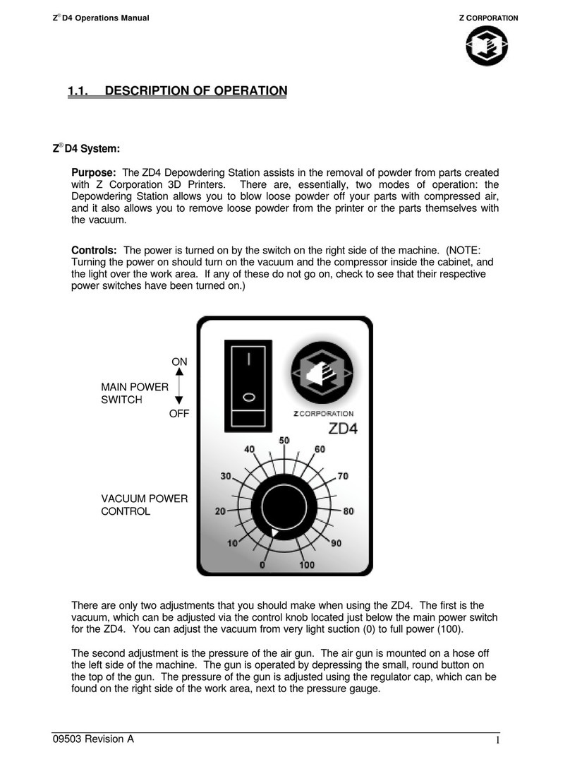
Zcorporation Z 406 User manual

Z406 System User Manual
September 2004
© 2003-2004 Z Corporation Part Number 09520
Z®406 3D Color Printer User Manual
Z Corporation
Type II
Revision D

Z Corporation Z406 System User Manual
2Z Corporation Service (781)852-5050/(877)88-ZCORP
Table of Contents:
1YOUR Z406 SYSTEM..................................................................................................8
1.1 INTRODUCTION ...................................................................................................8
1.1.1 OVERVIEW..................................................................................................................8
1.1.2 HOW IT WORKS..........................................................................................................9
1.2 THE PARTS OF THE Z406 3D PRINTER...........................................................12
1.3 THE PARTS ON THE PRINTER ASSEMBLY AND GANTRY............................13
1.4 Z406 SYSTEM COMPONENTS..........................................................................14
1.5 PRINTING A PART OVERVIEW .........................................................................15
1.5.1 STEP 1: PREPARING THE 3D PRINTER .................................................................15
1.5.2 STEP 2: IMPORTING THE FILE................................................................................15
1.5.3 STEP 3: PRINTING THE PART.................................................................................15
1.6 USEFUL TIPS......................................................................................................15
1.6.1 PART SETUP AND POST-PROCESSING ................................................................15
1.6.2 PART INFILTRATION................................................................................................16
2PREPARING THE Z406 3D PRINTER......................................................................18
2.1 HARDWARE CONTROLS...................................................................................18
2.2 PREPARING THE 3D PRINTER.........................................................................19
2.2.1 FILLING THE FEED BOX WITH POWDER ...............................................................20
2.2.2 CLEANING THE SERVICE STATION........................................................................24
2.2.3 CHECKING FLUID LEVELS.......................................................................................26
2.2.4 CHECKING POWDER OVERFLOW BIN...................................................................27
2.2.5 PUTTING THE MACHINE ONLINE............................................................................28
3USING ZPRINT SOFTWARE ....................................................................................29
3.1 OPEN OR IMPORT THE FILE.............................................................................29
3.2 ORIENTING THE PART......................................................................................30
3.2.1 PART CONTAINING AN OPENING OR HOLLOW AREA .........................................30
3.2.2 PART CONTAINING OVERHANGS ..........................................................................30
3.3 CHECKING BUILD SETTINGS ...........................................................................31
3.3.1 POWDER SETTINGS................................................................................................32
3.4 PRINTING THE BUILD........................................................................................33
4POST PROCESSING THE PART..............................................................................34
4.1 REMOVING THE FINISHED PART.....................................................................34

Z406 System User Manual Z Corporation
www.zcorp-users.com 3
4.2 DEPOWDERING THE PART...............................................................................35
4.2.1 ZD4I DEPOWDERER DETAIL...................................................................................36
4.2.2 ZD4 DEPOWDERER DETAIL....................................................................................39
4.2.3 USING THE EXTERNAL VACUUM BAG LINER .......................................................42
4.3 DRYING THE PART.............................................................................................45
4.3.1 STARCH AND PLASTER PARTS..............................................................................45
4.3.2 ZCAST PARTS ..........................................................................................................45
4.3.3 POST PROCESSING TOOLS ...................................................................................46
5INFILTRATING THE PART........................................................................................49
5.1.1 USING Z-MAXTM EPOXY...........................................................................................49
5.1.2 USING Z-BONDTM CYANOACRYLATE.....................................................................51
5.1.3 USING Z-SNAPTM EPOXY.........................................................................................52
5.1.4 USING PARAPLAST X-TRA WAX.............................................................................53
6APPLICATIONS .........................................................................................................54
6.1 GLUING MULTI-PIECE PARTS...........................................................................55
6.2 PAINTING PARTS................................................................................................56
6.3 POLYESTER RESIN............................................................................................57
6.4 ELECTROPLATING.............................................................................................58
6.5 WATER TRANSFER PRINTING..........................................................................59
6.6 INVESTMENT CASTING .....................................................................................62
6.7 FLEXIBLE PARTS................................................................................................64
6.8 THERMOFORMING.............................................................................................65
6.9 RTV MOLDING.....................................................................................................67
7MAINTENANCE .........................................................................................................73
7.1 CHANGING THE PRINT HEADS.........................................................................74
7.2 ALIGNING THE PRINT HEADS...........................................................................76
7.3 COLOR ALIGNMENT...........................................................................................82
7.4 FLUSHING THE BINDER ....................................................................................84
7.5 GREASING THE FAST AXIS...............................................................................84
7.6 GREASING THE SLOW AXIS .............................................................................85
7.7 OILING THE SNOWPLOWS................................................................................86
7.8 CLEAN UNDER THE GANTRY ...........................................................................86
7.9 GREASING THE PISTON SCREWS...................................................................87
7.10 REPLACING THE SCRAPER BLADE.................................................................88

Z Corporation Z406 System User Manual
4Z Corporation Service (781)852-5050/(877)88-ZCORP
8CHANGING THE BINDER SUPPLY .........................................................................91
9CHANGING MATERIAL SYSTEM ............................................................................92
9.1 USING ZCAST POWDER....................................................................................97
9.1.1 GENERAL INFORMATION........................................................................................97
9.1.2 USING ZCAST ON YOUR Z406 3D PRINTER..........................................................97
9.1.3 LOADING ZCAST INTO THE Z406 3D PRINTER .....................................................99
9.1.4 SETTING UP ZCAST BUILDS...................................................................................99
9.1.5 POST PROCESSING ZCAST PARTS.......................................................................99
9.1.6 MATERIAL ORDERING.............................................................................................99
9.1.7 RECYCLING ............................................................................................................100
9.1.8 STORAGE................................................................................................................100
9.1.9 DISPOSAL ...............................................................................................................100
9.1.10 QUESTIONS AND SUPPORT .................................................................................100
9.2 USING ZP250 POWDER...................................................................................100
9.2.1 MACHINE SETUP....................................................................................................100
9.2.2 SOFTWARE SETUP................................................................................................101
9.2.3 PART REMOVAL AND POST PROCESSING.........................................................103
9.2.4 INFILTRATION ADDENDUM...................................................................................105
10 TROUBLESHOOTING.............................................................................................106
10.1 THE BINDER SOLUTION IS BEING APPLIED IN ERRATIC STRIPES...........106
10.2 THE SOFTWARE FREEZES DURING USE....................................................106
10.3 THIN PLANAR PARTS ARE WARPING .......................................................106
10.4 NOTHING HAPPENS WHEN I TRY TO PRINT ............................................106
10.5 MY STARCH-BASED PARTS ARE UNUSUALLY “CAKEY” ............................107
10.6 PARTS ARE UNUSUALLY WEAK OR CRUMBLY...........................................107
10.7 PRINTER LOOKS LIKE IT IS PRINTING, BUT IS NOT LAYING DOWN BINDER107
10.8 AIR ENTERED THE FLUID LINES....................................................................108
10.9 COMMUNICATION ERRORS BETWEEN PRINT HEAD AND PRINTER........109
11 Z406 SYSTEM DETAILS.........................................................................................110
11.1 DESCRIPTION OF REAR I/O PANEL...............................................................110
12 SYMBOLS USED.....................................................................................................111
12.1 SYSTEM SPECIFICATIONS.............................................................................112
12.2 MATERIAL STORAGE PRECAUTIONS...........................................................113
12.3 ERROR CODES ................................................................................................113
13 INDEX.......................................................................................................................117
Z406 System User Manual Z Corporation
www.zcorp-users.com 5
APPENDIX I
ZCast 501 Design Guide....................…………………………………………………..119

Z Corporation Z406 System User Manual
6Z Corporation Service (781)852-5050/(877)88-ZCORP
Table of Figures
Figure 1. The Printing Process ................................................................................................. 9
Figure 2: The Z406 3D Printer Shelling and Infrastructure Features ..................................... 10
Figure 3: Illustration of Z406 System Print Orientations........................................................ 11
Figure 4: The Z406 3D Printer................................................................................................ 12
Figure 5: Gantry and Printer Assembly................................................................................... 13
Figure 6: Z406 System Components...................................................................................... 14
Figure 7: Z406 Control Panel.................................................................................................. 18
Figure 8: Service Station Detail ............................................................................................. 24

Z406 System User Manual Z Corporation
www.zcorp-users.com 7
Use of Equipment
The Equipment was manufactured under patents licensed to Z Corp. to be used for the fabrication of
appearance models and prototypes. Other uses may be restricted; contact Z Corporation for further
information.
The Equipment is designed to be used by design engineers and other professionals in the production
of early-stage 3D appearance models and prototypes. The Equipment is not to be used to produce,
either directly or indirectly, medical or other products that may require precise dimensions or
tolerances to ensure the safe and effective operation of such products. You agree to indemnify,
defend and hold Z Corporation and its officers, directors and employees harmless from and against
any and all claims, losses, damages, costs and expenses resulting from any use of the Equipment
other than for the production of early-stage appearance models and prototypes.
If you have purchased all relevant casting-specific products as recommended by Z Corp. (casting-
specific service contract, hardware, software, and consumables), as well as a casting license, then
you are authorized to utilize the Equipment to fabricate molds for casting.

Z Corporation Z406 System User Manual
8Z Corporation Service (781)852-5050/(877)88-ZCORP
1 YOUR Z406 SYSTEM
1.1 INTRODUCTION
1.1.1 OVERVIEW
This Z406 3D Color Printer Manual will speed you along the path towards quickly and
inexpensively building parts. The manual contains the following sections:
1. Introduction. This section will give you an overview of the principles behind the Z406
System, familiarize you with the terminology we will use to describe the Z406 System
and introduce you to some of the features of this manual. This section concludes with an
outline of the three quick and easy steps to printing parts.
2. Preparing the Z406 3D Printer. This section will guide you through putting powder,
binder solution and wash fluid in the Z406 3D Printer, and preparing the system to print a
part.
3. Using ZPrint Software. This section gives you an overview of how to set up a build on
the ZPrint Software. For more information about the softwre and its features, please refer
to the ZPrint User Manual.
4. Post Processing a Part. This section guides you through removing your printed part,
removing any excess powder and infiltrating the part with resin to improve strength and
finish.
5. Applications. This section will teach you various ways to maximize the versatility of your
printer through the implementation of advanced part processing techniques.
6. Maintenance. This section contains instructions for keeping your Z406 3D Printer in
proper condition through regular preventative maintenance.
7. Changing the Binder Supply. This section gives detailed instructions how to change
between color and monochrome modes.
8. Changing Material Systems. This section will guide you through changing binder and
powder systems.
9. Troubleshooting. This section offers some troubleshooting tips.
10. Z406 System Details.This section contains system specifications about the Z406 3D
Printer.
11. Index.

Z406 System User Manual Z Corporation
www.zcorp-users.com 9
1.1.2 HOW IT WORKS
The Z406 System is based on the Massachusetts Institute of Technology’s patented 3DP™(3D
Printing) technology.
The software first converts a three-dimensional design built using 3D CAD into cross-sections or
slices that can be between 0.003” – 0.009” (0.0762 - 0.2286 mm) thick.
The Z406 3D Printer then prints these cross-sections one after another from the bottom of part to the
top.
Inside the Z406 3D Printer there are two pistons (see Figure 1.)The feed piston is represented in the
diagrams below on the left and is shown in the ‘down’ position filled with powder. The build piston is
the piston on the right, shown below in the ‘up’ position. Also represented in the diagrams is the roller
(drawn as a circle) and the print assembly (drawn as a square.) On the Z406 3D Printer, the roller
and the print assembly are mounted together on the gantry which moves horizontally across the build
area.
To begin the 3D printing process, the printer first spreads a layer of zp series powder in the same
thickness as the cross section to be printed. The Z406 print heads then apply a binder solution to
the powder causing the powder particles to bind to one another and to the printed cross-section one
level below. The feed piston comes up one layer and the build piston drops one layer. The Z406 3D
Printer then spreads a new layer of powder and repeats the process, and in a short time the entire
part is printed.
Step 1: As the gantry traverses left
to right, the roller collects powder. Step 2: The roller spreads a thin
layer of powder over the build
piston.
Step 3: The roller discharges
excess powder down the powder
overflow chute.
Step 4: As the gantry traverses
right to left, the print head prints
the part cross-section.
Step 5: The feed piston moves up
one layer, the build piston moves
down one layer, and the process is
repeated.
Figure 1. The Printing Process

Z Corporation Z406 System User Manual
10 Z Corporation Service (781)852-5050/(877)88-ZCORP
The Z406 3D Printer employs several techniques to quickly build parts. First, binder solution is
applied in a higher concentration around the edges of the part, creating a strong “shell” around the
exterior of the part. Within parts, the Z406 3D Printer builds an infrastructure by printing strong
scaffolding within part walls with a higher concentration of binder solution. The remaining interior
areas are printed with a lower saturation, which gives them stability, but prevents over-saturation,
which can lead to part distortion of the part.
Figure 2: The Z406 3D Printer Shelling and Infrastructure Features
After printing, the part is removed from the powder bed, depowdered and dried. The part can then be
infiltrated with wax, epoxy, or other materials to increase strength and durability. More information on
different infiltrants can be found in Section 4.4, Infiltrating the Part. You will have the part in your
hands and can start improving your design within the same day—usually within hours.
Because the powder layers support the structures being printed above, the printer creates parts
without support structures and can print parts with complex geometries that are impossible for other
systems.
There are several important characteristics of the Z406 3D Printer that will help you print the best
parts for your intended purpose.
Part Placement. The software will place the parts within the build box to maximize build speed, the
most important criteria for the majority of our users. The software positions the parts with the
smallest dimension in the z (vertical) axis. For more information, refer to the ZPrint Software User
Manual. In addition to part placement, the following other characteristics should be considered.
Strength. The ultimate strength of the part will be somewhat affected by its orientation within the
print box. The part will be strongest along the y-axis and the x-axis and less strong along the z-axis.
This is because the cross sections are printed in continuous strips along the y or the “fast” axis (the
print heads direction of travel), bands across the x or the “slow” axis (the gantry direction of travel)
and laminated layers along the z-axis. (See figure 3). This discussion only applies to untreated
parts; once parts are infiltrated, they uniformly take on the strength characteristics of the infiltrating
material.
Exterior walls
printed at higher
saturation
Interior infrastructure
printed at a higher
saturation
Other interior areas
printed at lower
saturation

Z406 System User Manual Z Corporation
www.zcorp-users.com 11
Figure 3: Illustration of Z406 System Print Orientations
Accuracy. The accuracy of the system depends on the materials you choose. You can employ the
anisotropic scaling feature in the software to adjust for expected shrinkage and bring your parts into
true scale. More information on anisotropic scaling factors are found in Section 3.3.1, Powder
Settings.
Strong
z-axis
x-axis
y-axis
Most Strong
Less Strong

Z Corporation Z406 System User Manual
12 Z Corporation Service (781)852-5050/(877)88-ZCORP
1.2 THE PARTS OF THE Z406 3D PRINTER
Carriage
Service Station
Fast Axis Rail
Feed Box
Control Panel
Top Cover
Build Box
Scraper Blade
Color Binder Solution
Clear Binder Solution
Wash Fluid
Powder Overflow Bin
Waste Fluid
Figure 4: The Z406 3D Printer

Z406 System User Manual Z Corporation
www.zcorp-users.com 13
1.3 THE PARTS ON THE PRINTER ASSEMBLY AND GANTRY
Carriage Cover
Print Heads
Scraper Cover
Scraper
Snowplows
Grease Fittings
Figure 5: Gantry and Printer Assembly

Z Corporation Z406 System User Manual
14 Z Corporation Service (781)852-5050/(877)88-ZCORP
1.4 Z406 SYSTEM COMPONENTS
Z406 3D Printer
ZD4i Depowdering Station
Figure 6: Z406 System Components

Z406 System User Manual Z Corporation
www.zcorp-users.com 15
1.5 PRINTING A PART OVERVIEW
Printing a part using the Z406 3D Printer is fast, easy, clean and fully compatible with an office
environment. This manual will show tips on how to print the most challenging parts, but for most
purposes, printing a part is as simple as 1-2-3.
1.5.1 STEP 1: PREPARING THE 3D PRINTER
Carefully following the steps outlined in Chapter 3, you can prepare the 3D printer in less than ten
minutes. You will put powder in the feed piston, and ensure fluid levels are correct and that the
powder overflow bin is empty.
1.5.2 STEP 2: IMPORTING THE FILE
Upon launching the ZPrint Software, you will be presented with the ‘Open’ dialog box. Select the file
you wish to print. The software allows you to open a variety of monochrome and color file formats
including STL, PLY, SFX, VRML (WRL), BLD, ZEC, ZBD and ZCP files. The software also allows you
to move, scale, and/or rotate your part. For more information, refer to the ZPrint Software User
Manual.
1.5.3 STEP 3: PRINTING THE PART
The Z406 3D Printer prints most parts in minutes and prints even the largest parts in a few hours.
You may then remove the part, depowder any excess powder and dry and infiltrate the part with wax
or other materials to give the part the desired strength and finish. The post-processing phase takes
less than ten minutes for small parts and only an hour or so for large parts.
Once you have completed these steps you are ready to start using parts to improve design,
communicate with other departments and reduce the time it takes you to get new products to market.
1.6 USEFUL TIPS
1.6.1 PART SETUP AND POST-PROCESSING
1.6.1.1 Part Setup, Orientation, and Print Settings
•Do not tightly pack parts into the build. Keep in mind that you will need to depowder and
remove them from the build box. Allowing a little bit of room around the part so you can
vacuum the powder away and get your fingers around or under it.
•Orient parts so delicate features are supported in the z-axis, i.e. keep the attaching feature
directly below the fragile features. If a delicate feature is only supported by unprinted powder
the chances of breaking that small feature during depowdering is greatly increased.
•When building delicate parts use the “Fixture” function to cradle the part. Raising the part
0.25” (6.4 mm) from the bottom of the build and creating a fixture under the part will produce
a cradle that can be handled. The part inside the cradle can easily be transported to an oven
or the depowderer.
•Do not enable the bleed compensation feature if you are building a part with features under
0.050" (1.27 mm). Enabling bleed compensation may reduce the feature size.
•To increase the strength of thin parts, you can decrease the layer thickness to 0.0035” (0.089
mm) if you are using one of the zp®100 series (plaster-based) powder systems. Then choose
to override the saturation values. Input the saturation values used for printing at 0.004” (0.102

Z Corporation Z406 System User Manual
16 Z Corporation Service (781)852-5050/(877)88-ZCORP
mm). This increases the binder to powder ratio and wets more of the resins in the powder
system. As you increase the strength of the part in this manner you are also inceasing the
amount of time to dry the part. Use of the removable build plate and oven drying the part are
recommended.
1.6.1.2 Gross and Fine Depowdering
•Become familiar with where the parts are placed and how they are oriented in the build box
so you do not accidentally bump or brush against a fragile part during the depowdering
process.
•When performing the gross depowdering (removal of excess powder in the build box) do not
plunge the vacuum nozzle into the powder bed. Begin at the outer perimeter of the build box,
slowly work your way into the build. Hold the tip of vacuum nozzle approximately 0.25” (6.4
mm) to .375” (9.5 mm) away from the powder and allow the vacuum to pull the powder up.
Slanting the vacuum nozzle will enable you to control the suction. This will decrease the
chance of breaking a part that is hidden beneath the surface of the powder.
•While fine depowdering in the depowderer, always start with a low air pressure and gradually
increase the pressure as the fine details and features of the part become visible. When the
top and sides of the part are completely depowdered tilt the part onto one of its sides.
Handle the part carefully. The part may be fragile and brittle before infiltration. If none of the
sides of the part will be able to support the weight of the part you can apply a small amount of
resin or epoxy to strengthen it. You want to be careful not to let any of the infiltrant come into
contact with any unprinted powder that may still be on the part. Let the infiltrant dry before
continuing to depowder.
1.6.1.3 Use of the Removable Build Plate
•The removable build plate is an excellent tool for the new user. It allows you to quickly
remove the part from the build bed and begin printing again. The build plate also allows the
user to easily transport the part to the oven (at temperatures below 150oF or 66oC) or the
depowdering station without ever having to handle the part.
•If you choose to use the removable build plate keep in mind that you want to orient the parts
so that the part does not collapse when powder flows out from the sides of the part after the
removable build plate is lifted from the build bed.
1.6.1.4 Oven Dry the Part
•Although the part can be handled when it is not completely dried, the part reaches full
strength when dried. Placing the part in an oven at temperatures less than 200°F (93oC) for
2-4 hours will dramatically increase the strength of the part. This is only recommended for
plaster-based powders. If using the removable build plate, remove the part from the
removable build plate before placing in the oven.
1.6.2 PART INFILTRATION
1.6.2.1 When Using Z-BondTM Resin
•Always infiltrate the most delicate features of the part first. Z-Bond resin gives almost
immediate strength to the area of the part that has been infiltrated. As you handle the areas
of the part that have been infiltrated it will be less likely to break it.
•Try to avoid infiltrating the part by applying Z-Bond resin from spot to spot. Pick a good
starting place hold that area upward relative to the rest of the part. With your free hand,
place the tip of the Z-Bond bottle against the part and allow the cyanoacrylate (CA) to flow
from the bottle. It is important that the CA flows at a uniform rate making it easier for you the
judge how quickly it will flow from the tip of the bottle before it wicks into the part. By seeing
how quickly it wicks into the part you will be able to judge where and how quickly to move the

Z406 System User Manual Z Corporation
www.zcorp-users.com 17
tip of the bottle while applying the CA, being sure not to apply the CA to the same place more
than once.
1.6.2.2 When Using a Z-MaxTM and Z-SnapTM Epoxy
•If the part has delicate features, infiltrate them last as the feature will be less strong after
being infiltrated until the epoxy begins to cure. This will decrease the chance the feature will
break from the part if nudged or bumped.
•If the part has multiple delicate features or it is impossible to handle the part without breaking
a feature you may infiltrate these features only. Allow the Z-Max and Z-Snap epoxy to cure.
Then infiltrate the rest of the part. This will add time to post-processing the part but it
ensures that you have a good strong part without any fractures.

Z Corporation Z406 System User Manual
18 Z Corporation Service (781)852-5050/(877)88-ZCORP
2 PREPARING THE Z406 3D PRINTER
2.1 HARDWARE CONTROLS
The front control panel on the Z406 3D Printer has the following features:
Figure 7: Z406 Control Panel
Online Button.
Enables and
disables printer
communication.
Spread Button. This button allows
the user to move the gantry from left
to right. Moving the gantry from left
to right allows you to spread powder
over the build box. Holding down this
button will result in continuous
spreading of powder.
Feed Up/Down Buttons. Allows
the user to raise or lower the
piston in the feed box. A light tap
raises or lowers one layer
thickness; holding down causes
continuous motion. Holding
down the feed down button will
cause the feed piston to drop to
the bottom.
Build Up/Down Buttons.
Allows the user to raise
or lower the build box. A
light tap raises or lowers
one layer thickness;
holding down causes
continuous motion.
PLEASE NOTE: When the s
y
stem is online
,
all buttons exce
p
t the online button are disabled.
LCD Panel. Displays
the current status of
the Z406 3D Printer.

Z406 System User Manual Z Corporation
www.zcorp-users.com 19
2.2 PREPARING THE 3D PRINTER
If the printer is off, switch it on by pressing and releasing the power ON/OFF switch. The gantry will
move slowly as it orients itself. We recommend that you leave the printer on at all times—in sleep
mode the printer will exercise the print heads during periods of inactivity to prevent clogging.
1. Wait for the green online light indicating that the power-up procedure has completed. The warm
up process should take between 60 and 90 seconds.
2. Take machine offline by pressing and releasing the online button.
3. Open the top cover to gain access to the build area.
Technical Tip -
LEAVE THE MACHINE ON! This allows the printer to perform a periodic self maintenance.

Z Corporation Z406 System User Manual
20 Z Corporation Service (781)852-5050/(877)88-ZCORP
2.2.1 FILLING THE FEED BOX WITH POWDER
3. Grip the powder scoop and using a stabbing
motion, insert it repeatedly into the loose
powder to compact it. Continue for about
10-15 seconds until the powder feels firm.
4. When feed box is filled to top, take the
tamper and slowly press it onto the powder
surface. Be careful not to “slap” the tamper
into the feed box, which will produce
airborne particles. About 10-15 pounds of
force will give a smooth, flat, and compact
surface. Failure to firmly pack feed box will
affect part quality.
1. Press and hold the feed down button until
the piston automatically moves towards the
bottom of the feed box. The piston will stop
when it reaches the bottom. Move the build
up button until it reaches the top. When
completed, the front display will read “F:
100% B: 100%”
2. Carefully scoop powder from the bucket and
place in the feed piston.
WARNING: Use only powder supplied by Z Corporation. Use of any other material may
impact the performance and/or safety of your Z406 System and will void warranty of
equipment.
PLEASE NOTE: Do not compact ZCast
powder. Use the tamper to level the
powder but do not apply any pressure.
Other manuals for Z 406
1
Table of contents
Other Zcorporation 3D Printer manuals

Zcorporation
Zcorporation D4 User manual

Zcorporation
Zcorporation Z 406 User manual

Zcorporation
Zcorporation Spectrum Z 510 User manual

Zcorporation
Zcorporation ZPRINTER 310 PLUS User manual

Zcorporation
Zcorporation ZPrinter 650 User manual

Zcorporation
Zcorporation ZPrinter 650 User manual

Zcorporation
Zcorporation SPECTRUM Z M510 User manual

Zcorporation
Zcorporation zprinter 450 User manual

Zcorporation
Zcorporation ZPrinter 450 User manual

Zcorporation
Zcorporation Z402C User manual