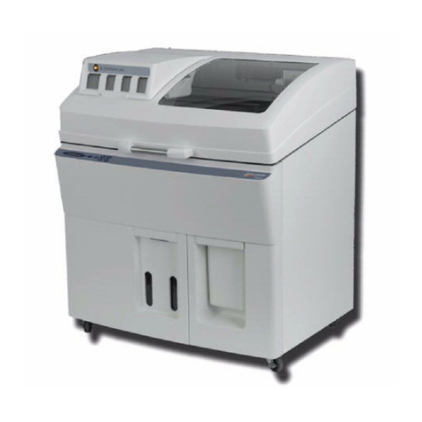
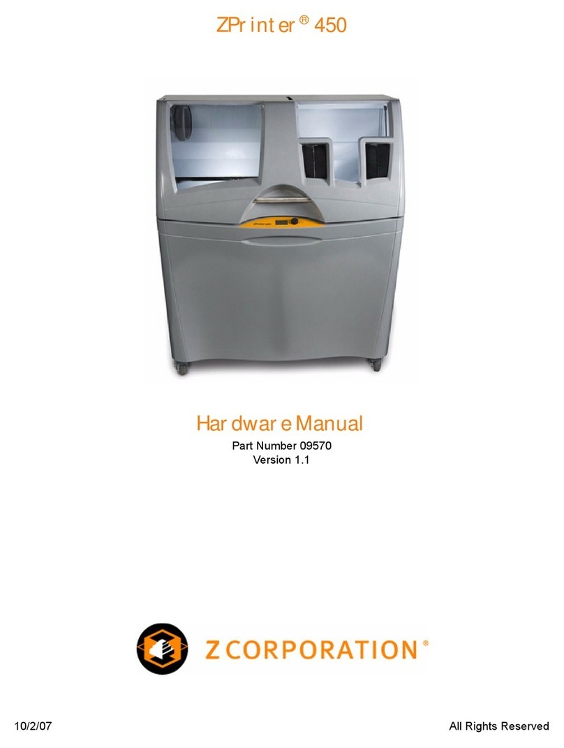
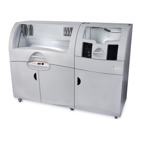
Zcorporation ZPrinter 650 User manual

10/21/08 All Rights Reserved
ZPrinter®650
Hardware Manual
Part Number 09577
Rev. A

ZPrinter®650 Hardware Manual
zcentral.zcorp.com i All Rights Reserved
10/21/08
Notices
Copyright and Trademarks
Copyright © Z Corporation 1995-2008. All rights reserved. The information in this document may not be
duplicated or transmitted in any way without the express written consent of Z Corporation. The information
contained herein is for the use of Z Corporation customers, who are permitted to create brief excerpts for
the purposes of training and review. This information may not be incorporated in any commercial pro-
grams, books, databases, or in any kind of software without the consent of Z Corporation.
Z, Z Corporation, zp, zb, ZMap, ZPhoto, Z-Cure, Z Prints, ZPrinter, ZCast, ZScanner, ZScan and the Z
Corp. logo and design are pending/registered trademarks of Z Corporation.
ZPrint® 7.8 System Software Copyright (c) 1996-2008 Z Corporation.This software is based in part on the
work of the Independent JPEG Group.
PNG library libpng version 1.2.2 Copyright (c) 1998-2002 Glenn Randers-Pehrson, (Version 0.96 Copy-
right (c) 1996, 1997 Andreas Dilger), (Version 0.88 Copyright (c) 1995, 1996 Guy Eric Schalnat, Group 42,
Inc.)
ZLIB general purpose compression library version 1.1.4, Copyright (C) 1995-2002 Jean-loup Gailly and
Mark Adler.
Microsoft Windows is a trademark of Microsoft Corporation.
Z Corporation acknowledges the trademarks of other organizations for their respective products or ser-
vices mentioned in this documentation.
Proprietary Information
Information contained in this document is the confidential property of Z Corporation. Recipient shall not dis-
close such Information to any third party, and shall not use it for any purpose whatsoever other than what is
required to install and use the ZPrinter® 650.
Use of Equipment
Z Corporation's Equipment, and use of the Equipment, may be subject to limitations imposed under
patents licensed to or owned by Z Corp., and is to be used solely for the fabrication of appearance models
and prototypes using new Z Corporation-supplied consumable from Z Corporation or its authorized
distributors in the original packaging. Other uses may be restricted; contact Z Corporation for further
information. Consult the User's Manual before operation of any Z Corporation Equipment. The Equipment
may be covered by the following U.S. Patents and/or U.S. Patent Applications:
5,204,055 5,340,656 5,387,380 6,007,318 6,375,874 5,902,441
6,416,850 6,610,429 6,403,002 5,660,621 5,851,465 6,397,922
6,036,777 6,989,115 7,037,382 7,291,002 7,387,359 7,087,109
7,332,537 11/335,282 11/860,087 60/558,940 12/118,899 11/000,100
11/606,960 60/808,721 11/807,325 11/807,329 11/807,175 11/807,237
09/706,350 09/835,292 11/453,695 60/472,221 60/499,220 11/732,490
60/879,703 11/952,727 12/035,743.
The Equipment is designed to be used by design engineers and other professionals in the production of
early-stage 3D appearance models and prototypes. The Equipment is not to be used to produce, either
directly or indirectly, medical or other products that may require precise dimensions or tolerances to ensure
the safe and effective operation of such products. You agree to indemnify, defend and hold Z Corporation
and its officers, directors and employees harmless from and against any and all claims, losses, damages,
ZPrinter®650 Hardware Manual
zcentral.zcorp.com ii All Rights Reserved
10/21/08
costs and expenses resulting from any use of the Equipment other than for the production of early-stage
appearance models and prototypes.
Warranty
Your ZPrinter® is guaranteed to be free of defects in materials and workmanship, when used for produc-
tion of early-stage appearance models and prototypes and with Z Corporation consumables, for the period
described below under WARRANTY PERIOD. All consumables and materials are guaranteed to perform
as described in their specifications when stored and used as directed, up to the expiry date printed on the
label. THE COMPANY MAKES NO WARRANTIES, EXPRESS OR IMPLIED, AND DISCLAIMS ALL WAR-
RANTIES INCLUDING, BUT NOT LIMITED TO, IMPLIED WARRANTIES OF MERCHANTABILITY AND
FITNESS FOR A PARTICULAR PURPOSE AND ANY OTHER OBLIGATIONS OR LIABILITIES
WHETHER IN CONTRACT, WARRANTY, NEGLIGENCE OR OTHERWISE. THE COMPANY IS NOT LIA-
BLE FOR ANY DIRECT, INDIRECT, SPECIAL, PUNITIVE, CONSEQUENTIAL OR INCIDENTAL DAM-
AGES INCLUDING, WITHOUT LIMITATION, DAMAGES FOR LOSS OF BUSINESS PROFITS OR BUSI-
NESS INTERRUPTION ARISING OUT OF THE USE OR INABILITY TO USE PRODUCTS OR
SERVICES SOLD HEREUNDER. IN NO EVENT WILL THE COMPANY'S LIABILITY EXCEED THE
TOTAL CHARGE OF THIS ZPRINTER® 650.
WARRANTY PERIOD: In the U.S., warranty is for 90 days and covers service, parts and training material.
In the EU, warranty is for 1 year and covers service, parts and training material.
Symbols
The following symbols are used on the ZPrinter 650 and in this manual.
Change History
Rev. A 10/21/2008
General Caution: User should use care to avoid
possible damage to equipment.
Hot Surface: User should use care when working
near or on the labelled item.
High Voltage: User should use appropriate electri-
cal safety precautions.

ZPrinter®650 Hardware Manual
zcentral.zcorp.com iii All Rights Reserved
10/21/08
ZPrinter®650
Hardware Manual
TABLE OF CONTENTS
1 ZPrinter 650 Overview ............................................................... 1
1.1 New Features ........................................................................................... 1
1.2 Specifications............................................................................................ 1
1.3 Computer/System Requirements.............................................................. 2
1.3.1 Recommended System .................................................................... 2
1.4 How 3D Printing Works............................................................................. 2
1.5 3D Printing Process Diagram ................................................................... 4
1.6 Important Terms ....................................................................................... 4
1.7 ZPrinter 650 Components......................................................................... 6
1.7.1 System Exterior ............................................................................. 6
1.7.2 Printer Interior ................................................................................. 7
1.7.3 Post-Processing Unit (PPU) Interior .............................................. 8
1.7.4 Printer Storage.................................................................................. 9
1.7.5 Post-Processing Unit (PPU) Storage................................................ 10
1.8 ZPrinter 650 Rear View ........................................................................... 11
1.9 Service Station.......................................................................................... 12
1.10 Parking Caps .......................................................................................... 13
1.11 Carriage, Print Heads, and Pogo Pins.................................................... 14
1.11.1 Front View....................................................................................... 14
1.11.2 Top Inside View .............................................................................. 15
1.12 LCD Menu And Control Knob (Control Panel) ........................................ 16
1.12.1 Control Knob Operations ................................................................ 16
1.13 LCD Menu Overview............................................................................... 16
1.14 Accessories Kit ....................................................................................... 17
1.15 Where To Go For More Information........................................................ 17
2 Setup And Print The Build ........................................................ 19
2.1 Overview To Printing Speed, Part Strength, And Part Accuracy .............. 19
2.2 Overview - Part Orientation ...................................................................... 19
2.2.1 Parts Containing an Opening or Hollow Area ................................... 20
2.2.2 Parts Containing Overhangs............................................................. 20
2.2.3 Parts Containing Cylindrical Features .............................................. 20
2.3 ZPrint/ZEdit Installation............................................................................ 21
2.3.1 ZEdit ................................................................................................. 21
2.4 Open A Part In ZPrint ............................................................................... 21
2.5 ZPrint Main Window.................................................................................. 22
2.6 Check Or Change The Default Printer Settings........................................ 22
2.7 Check The Default Powder Settings......................................................... 24
2.7.1 Create A New Powder Type ............................................................. 24

ZPrinter®650 Hardware Manual
zcentral.zcorp.com iv All Rights Reserved
10/21/08
2.8 Transform The Part in ZPrint .................................................................... 24
2.9 Fixtures ..................................................................................................... 26
2.9.1 Create a Fixture for an entire part..................................................... 27
2.9.2 Create a Fixture for a portion of a part.............................................. 28
2.10 Check the Build Layers for Errors or a Collision ..................................... 29
2.11 Check The Build Settings ....................................................................... 29
2.12 Prepare the Build Area ........................................................................... 30
2.13 Print the Build ......................................................................................... 31
2.14 Dry The Part ........................................................................................... 33
2.15 Automatic Powder Removal ................................................................... 33
2.16 Fine Powder Removal ............................................................................ 34
2.17 The Next Step......................................................................................... 35
3 Routine Cleaning ....................................................................... 36
3.1 Vacuum Excess Powder.......................................................................... 36
3.2 Empty The Debris Separator .................................................................... 37
3.3 Clean The Parking Caps........................................................................... 38
3.4 Clean The Fast Axis Rails and Carriage................................................... 41
3.5 Clean The Service Station ........................................................................ 42
3.5.1 Example - Dirty Service Station ........................................................ 42
3.5.2 Example - Clean Service Station ...................................................... 43
3.5.3 Cleaning Procedure .......................................................................... 43
4 Post-Processing With Z-Bond .................................................. 46
4.1 Preparation ............................................................................................... 46
4.2 Using the Post-Processing Unit ................................................................ 47
4.3 Post-Processing Using the Dipping Method ............................................. 48
4.4 Post-Processing Using the Drizzle Method .............................................. 48
5 Additional Operations ............................................................... 50
5.1 The Printer Status Dialog.......................................................................... 50
5.1.1 Ready to Print .................................................................................. 50
5.1.2 Not Ready to Print ........................................................................... 51
5.2 Change Print Head(s) ............................................................................... 52
5.3 Add Binder ................................................................................................ 55
5.4 Add Powder To The Feeder ..................................................................... 56
5.5 Add Cleaning Solution .............................................................................. 57
5.6 Replace the Waste Tray ........................................................................... 57
5.7 Position Build Piston (Build Bed) .............................................................. 58
5.8 Cover ........................................................................................................ 58
6 Printer Maintenance................................................................... 59
6.1 Fast Axis Bearing Lubrication ................................................................... 59
6.2 Piston Screw Lubrication .......................................................................... 60
6.3 Slow Axis Bearing Lubrication .................................................................. 62
6.4 Replace the Carbon Filter......................................................................... 63
6.5 Clean The Alignment Sensor Window ...................................................... 64
6.6 Clean The Fast Axis Pulleys..................................................................... 65
6.7 Clean The Slow Axis Rails and Pulleys .................................................... 65

ZPrinter®650 Hardware Manual
zcentral.zcorp.com v All Rights Reserved
10/21/08
6.8 Clean The Spreader Roller ....................................................................... 70
6.9 Printer Storage Preparation ...................................................................... 70
7 Troubleshooting the ZPrinter 650 ............................................ 71
7.1 Try This First............................................................................................. 72
7.2 Problems Powering Up ............................................................................. 73
7.3 Print Head Errors/ Weak Parts ................................................................. 74
7.3.1 Try This First..................................................................................... 74
7.4 Alignment Errors ....................................................................................... 76
7.5 Motion Errors - Fast Axis .......................................................................... 77
7.6 Motion Errors - Slow Axis ......................................................................... 79
7.7 Network Errors - Cannot Connect to Printer ............................................. 81
7.8 Network Errors - Packet Timeout.............................................................. 82
7.9 Part Quality Issues - General.................................................................... 82
7.9.1 Part Colors Do Not Match PC Monitor Colors .................................. 82
7.9.2 Parts Broken After Automatic Depowdering ..................................... 82
7.10 Part Quality Issues - Streaky or Striped Parts, Delamination ................. 84
7.11 Part Quality Issues - Bad Surface Finish ................................................ 85
7.11.1 Bad Horizontal Surface Finish ........................................................ 85
7.11.2 Bad Vertical Surface Finish ............................................................ 85
7.12 Miscellaneous Problems......................................................................... 86
7.12.1 Vacuum Has Low/No Suction ......................................................... 86
7.12.2 Binder Cartridge is Full But ZPrint Indicates Empty........................ 87
7.13 Error Codes and Messages - Background Details.................................. 88
7.14 Additional Information ............................................................................. 89
7.14.1 Materials ......................................................................................... 89
7.14.2 Service............................................................................................ 89
7.15 Calling for Service................................................................................... 89

ZPrinter®650 Hardware Manual ZPrinter 650 Overview
zcentral.zcorp.com 1 All Rights Reserved
10/21/08
1 ZPrinter 650 Overview
Welcome to the exciting world of 3D Printing with our newest 3D Printer, the ZPrinter 650. The ZPrinter
650 incorporates many new features that automate and streamline the 3D printing process. The full-color
capability, an easy-to-use, quiet, office-friendly design, combined with high-performance composite materi-
als, makes ZPrinter 650 the fastest, most cost-effective 3D printer available today for rapid prototyping.
This manual will instruct you on how to take care of your printer and give you an introduction to 3D Printing.
In addition, you can find information about 3D printing and its many applications and techniques on our
3DP User Web site at zcentral.zcorp.com.
This Web site is tailored to both beginner and advanced customers. We recommend that you register
immediately to receive free, unlimited access to this excellent resource.
1.1 New Features
The ZPrinter 650 is our fastest, most capable printer. We’ve built in the features customers most asked for:
• Larger build volume
• Higher resolution
• Automated Powder Loading/Removal/Recycling
• Quick-Load Binder and Cleaning Solution Cartridges
1.2 Specifications
Printer Dimensions and Type • With top cover closed: 79” wide x 30” deep x 57” high
(201 cm wide x 76 cm deep x 145 cm high)
• With top cover open: 79” wide x 30” deep x 75” high
(201 cm wide x 76 cm deep x 191 cm high)
• Crated: 87” wide x 48” deep x 64” high (221 cm wide
x 122 cm deep x 163 cm high
• Floor standing model on six casters. Two front cast-
ers are lockable.
• Full color capability; color shell thickness =.025”
(.635 mm)
• Integrated powder removal and vacuum units.
Printer Weight 750 lbs (340 kg)
Network Connectivity TCP/IP 100/10 Base T
Operating Environment
Ambient Temperatures
Ambient Relative Humidity
• Maximum Temp. Range: 50-80° F (10 - 26.6° C)
• Recommended Temp. Range: 55-75° F (12.7 -
23.9°C)
• Maximum RH Range: 15 - 60%, non-condensing
• Recommended RH Range: 20 - 55%, non-condens-
ing
(May experience sub-optimal performance at extremes.)

ZPrinter®650 Hardware Manual ZPrinter 650 Overview
zcentral.zcorp.com 2 All Rights Reserved
10/21/08
1.3 Computer/System Requirements
1.3.1 Recommended System
• Operating System: Microsoft Vista 32-bit or XP Professional
• Processor: Intel® Core™2 Duo Desktop Processor E8200 2.66Ghz or better
• Video: 512MB Video card (recommend nVidia Quadro FX1700)
• Memory: 4GB or better
• Hard Drive: 1 GB of free space
• Ethernet 10/100 Base T
These system configurations may require a higher performance computer based on file size and type. For
more information, please contact your local Reseller, or visit the support section of our Web site:
zcentral.zcorp.com.
1.4 How 3D Printing Works
The 3D Printing System is based on the Massachusetts Institute of Technology's patented 3DP™ Technol-
ogy (3D Printing). The 3D Printing process requires:
Build Volume 10” x 15” x 8” (254 mm x 381 mm x 203 mm)
1200 cubic inches build capacity
Build Speed 2-4 layers per minute
Layer Thickness .0035” - .004” (.089 - .102 mm)
Resolution 600 x 540 dpi print resolution
Noise Levels During Printing = 57dB
Emptying Overflow = 66dB
Vacuuming - Cover Open = 72dB
Fine Powder Removal = 72dB
CSA, CE Approval Meets CE certification standards and UL standards.
Power Requirements 100V, ~50-60 Hz, 15 Amp.
115V, ~50-60 Hz, 15 Amp.
230V, ~50-60 Hz, 8 Amp.
Note: Due to high amperage, a dedicated outlet is
strongly recommended.
Materials -
High Performance Composite Zp131 Powder
Zb61 Binder
Z Corp. is always evaluating new materials for use with
your printer. For the latest information check the Materials
section of our Web site:
zcentral.zcorp.com.
Print Heads 5 each HP11 (clear, black, cyan, magenta, yellow)
1520 jets total
Liquid Waste System Pull-out tray

ZPrinter®650 Hardware Manual ZPrinter 650 Overview
zcentral.zcorp.com 3 All Rights Reserved
10/21/08
• A 3D Printer
• Importing a solid 3D modeling file into the ZPrint Software
• Setting up your files to print in the ZPrint/ZEdit Software
• Printing, powder removal, and drying the part
• (Optional) Applying post-processing materials to the printed part
To start, the ZPrint Software takes a three-dimensional design file, (ZPrint is compatible with most 3D mod-
eling software files) and converts it into cross-sections, or layers, that are between 0.0035" - 0.004" (0.089
- 0.102 mm) thick. Before printing, ZPrint evaluates the part geometry and checks if there are enough
materials in the printer to print the number of layers required to build the part. If there are, the printer then
prints each layer, one after the other, from the bottom of the part to the top. If not, ZPrint will prompt you to
add powder, to add binder, or to change a print head before it will start the print job.
During printing, binder is first applied with a higher saturation to the edges of the part, creating a strong
“shell” for the part exterior. Next, an infrastructure that works like strong scaffolding is created for the part
walls, which are also built with a higher saturation of binder for added strength. The remaining interior
areas are printed with a lower binder saturation, which gives the part its stability.
When the part is finished printing, the printer heats up to the appropriate temperature and dries the part
while it is still in the Build Bed surrounded by powder. When the drying cycle is finished, an automatic pow-
der removal cycle empties the Build Bed of most of the excess powder around the part, and returns that
powder to the Feeder for reuse. After the bulk of the powder removed, the part is moved from the Build
Bed to the integrated Post-Processing Unit where any remaining powder is cleaned off the part.
After the part is powder-free, it is ready to be removed from the printer. You can evaluate the part as it is, or
you can choose to post-process the part with infiltration products to give it additional strength, durability,
and color vibrancy. With the finished part in your hands, you can start improving or modifying your design
within the same day, and usually within hours.

ZPrinter®650 Hardware Manual ZPrinter 650 Overview
zcentral.zcorp.com 4 All Rights Reserved
10/21/08
1.5 3D Printing Process Diagram
1.6 Important Terms
Air Wand - The tool located in the Post-Processing Unit that supplies air pressure. Use this tool to remove
all remaining powder from a part after the initial (automatic or manual) powder removal.
Alignment Sensor Window - Located on the underside of the Carriage unit. Wipe powder off of the Align-
ment Sensor Window every time you replace a print head, or whenever you remove a print head to clean
the contacts.
Binder - Solution that is dispensed through the HP11 print head and applied to the powder. The binder sat-
uration value will vary depending on the part geometry. The ZPrint software uses a default core and shell
saturation value that is suitable for most part geometries.
Build Bed - The 10” x 15” x 8” area in front of the Feeder where the part is printed. The platform of the
Build Bed can be raised or lowered using the appropriate command on the printer LCD menu. Before each
build, the printer fills the Build Bed with powder and then spreads a layer of powder to ensure the surface
of the Build Bed is completely smooth.
Build Chamber - The left, interior side of the printer that houses the Build Bed, Service Station, Parking
Caps, the Debris Separator, the Carriage, the Fast Axis assembly, the Vacuum Hose, the Heater Vent, and
the Feeder.
Carriage - Assembly that houses the Print Heads, Pogo Pin Connectors, and the Alignment Sensor Win-
dow.
Consumables - Powder-Binder-Infiltrant products that are available in a variety of systems for all of your
color or monochrome modeling needs. All consumables have been developed for the fastest printing
speeds and lowest materials costs.
Debris Separator - Located above the Heater Vent in the Build Chamber. Its function is to prevent chunks
of particles from going back into the printer Feeder during any vacuuming operation.
Deck - Area surrounding the Build Bed.
Depowder - Process of removing excess powder from a newly printed part. First, there is the initial (auto-
matic or manual) powder removal process, which removes the bulk of the powder after the part is dried in
the Build Bed. After the initial powder removal, there is the fine-powder removal process - which cleans the
part of all remaining powder.
Feeder - Printer component that stores powder. Powder that is vacuumed up after a build, or powder that
is automatically (or manually) emptied from the Build Bed, is recycled and returned to the Feeder for reuse.
Fast Axis - Printer component that houses the Carriage and the Fast Axis rails that the Carriage moves
on. The Fast Axis moves on the Slow Axis rails which are housed beneath the Build Chamber Deck.
Heater Vent - Located directly below the Debris Separator. The Heater Vent supplies heat to the Build
Chamber during the warm-up cycle, and during the drying cycle.

ZPrinter®650 Hardware Manual ZPrinter 650 Overview
zcentral.zcorp.com 5 All Rights Reserved
10/21/08
Infiltration - Process of applying various post-processing products (resins, wax, epoxy, etc.) to fully
depowdered parts to give them specific properties such as strength, durability, and color vibrancy.
LCD - Liquid Crystal Display.
Parking Caps - Printer component that prevents the print heads from drying out between print jobs. It is
important to clean the Parking Caps after every build. Beneath the Parking Caps is the Parking Spittoon,
which catches binder that is periodically ‘spit’ out of the printheads.
Platform - The bottom, metal plate of the Build Bed. The platform contains numerous small holes that
allow excess powder to escape through the bottom of the Build Bed during initial (automatic or manual)
powder removal. The platform can be raised or lowered by selecting the appropriate command on the
printer LCD menu.
Pogo Pins - Gold contact pins for the print head contacts. Clean the Pogo Pins with an alcohol swab
whenever a print head is removed, cleaned, or replaced.
Post-Processing Unit - The right side of the printer that houses the Post-Processing Tray and the Air
Wand. Printed parts are moved from the Build Bed to the Post-Processing Unit for final removal of any
powder left on the part, and for infiltration.
Powder - Very fine particles that are not bound together. Powder is spread layer by layer and saturated
with binder to create a solid object.
Print Head - There are five Print Heads for the ZPrinter 650 - clear, black, cyan, magenta, and yellow. All
are HP11 print cartridges. When a new HP11 print head is installed, the printer runs an automatic purge
cycle to clean the print head of its ink and to prepare it for dispensing binder. Note: Only HP11 model
C4810A Black cartridges can be used in the ZPrinter 650.
Print Head Contacts - The contact points on a print head cartridge that match up with the Pogo Pins.
Purge - Process of removing ink from the HP11 print head to prepare it for dispensing binder.
Service Station - Cleans the print head jets to remove powder residue during printing. It is extremely
important to clean the Service Station after every build to remove residue buildup that gets left on the Ser-
vice Station during a build. If the Service Station is not clean, your print heads will not get properly cleaned
and this will result in premature print head expiration.
Waste Tray - Absorbs the binder waste and will require changing only when you are prompted to in ZPrint.
Located at the front bottom of the printer.

ZPrinter®650 Hardware Manual ZPrinter 650 Overview
zcentral.zcorp.com 6 All Rights Reserved
10/21/08
1.7 ZPrinter 650 Components
The main components of the ZPrinter 650 system are highlighted below.
1.7.1 System Exterior
Number Component
1 Printer
2 Post-Processing Unit (PPU)
3 Control Panel
4 Printer Storage Compartment
5 PPU Storage Compartment
6 Arm Holes

ZPrinter®650 Hardware Manual ZPrinter 650 Overview
zcentral.zcorp.com 7 All Rights Reserved
10/21/08
1.7.2 Printer Interior
Number Component
1 Binder Cartridges
2DebrisSeparator
3 Heater Vent
4 Vacuum Hose
5 Service Station
6Deck
7 Fast Axis Assembly
8 Build Bed
9 Front Overflow
10 LCD Display
11 Control Knob

ZPrinter®650 Hardware Manual ZPrinter 650 Overview
zcentral.zcorp.com 8 All Rights Reserved
10/21/08
1.7.3 Post-Processing Unit (PPU) Interior
Number Component
1AirWand
2AirPressureControl Nut
3 Air Hose
4 Heater Vent
5 Carbon Filter
6 Post-Processing Tray
7 Accessory Tray

ZPrinter®650 Hardware Manual ZPrinter 650 Overview
zcentral.zcorp.com 9 All Rights Reserved
10/21/08
1.7.4 Printer Storage
Number Component
1 Tools and Acessories Storage
2 Cleaning Solution Cartridge
3 Print Head Storage
4WasteTray

ZPrinter®650 Hardware Manual ZPrinter 650 Overview
zcentral.zcorp.com 10 All Rights Reserved
10/21/08
1.7.5 Post-Processing Unit (PPU) Storage
Number Component
1 Tool Basket
2 Parts Trays
(shown under Dipping Kit)
3 Accessory Tray

ZPrinter®650 Hardware Manual ZPrinter 650 Overview
zcentral.zcorp.com 11 All Rights Reserved
10/21/08
1.8 ZPrinter 650 Rear View
Number Component
1 Power Switch
2 Power Cord
3NetworkCable
4 Electronics Box (E-Box)
Connections

ZPrinter®650 Hardware Manual ZPrinter 650 Overview
zcentral.zcorp.com 12 All Rights Reserved
10/21/08
1.9 Service Station
Number Component
1 Squeegee
2SpitPlate
3 Front Overflow

ZPrinter®650 Hardware Manual ZPrinter 650 Overview
zcentral.zcorp.com 13 All Rights Reserved
10/21/08
1.10 Parking Caps
Number Component
1 Parking Caps (5 total)
2 Parking Spittoon
(under Parking Caps)

ZPrinter®650 Hardware Manual ZPrinter 650 Overview
zcentral.zcorp.com 14 All Rights Reserved
10/21/08
1.11 Carriage, Print Heads, and Pogo Pins
1.11.1 Front View
Number Component
1 Print Head (removed)
2 Print Head Contacts
3 Pogo Pins (inside)
4 Septum
5 Print Head (installed)
6 Carriage Cover
Other manuals for ZPrinter 650
1
Table of contents
Other Zcorporation 3D Printer manuals

Zcorporation
Zcorporation Z402C User manual

Zcorporation
Zcorporation ZPrinter 450 User manual

Zcorporation
Zcorporation ZPrinter 650 User manual

Zcorporation
Zcorporation Spectrum Z 510 User manual

Zcorporation
Zcorporation Z 406 User manual

Zcorporation
Zcorporation Spectrum Z 510 User manual

Zcorporation
Zcorporation SPECTRUM Z M510 User manual

Zcorporation
Zcorporation zprinter 450 User manual

Zcorporation
Zcorporation D4 User manual

Zcorporation
Zcorporation ZPrinter 310 User manual