Zcorporation ZPrinter 450 User manual

10/2/07 All Rights Reserved
ZPrinter®450
Hardware Manual
Part Number 09570
Version 1.1

10/2/07 All Rights Reserved
Use Of Equipment
Z Corporation's Equipment, and use of the Equipment, may be subject to limitations imposed under pat-
ents licensed to or owned by Z Corp., and is to be used solely for the fabrication of appearance models
and prototypes using new Z Corporation-supplied consumables from Z Corporation or its authorized dis-
tributors in the original packaging. Other uses may be restricted; contact Z Corporation for further informa-
tion. Consult the User's Manual before operation of any Z Corporation Equipment. The Equipment may be
covered by the following U.S. Patents and/or U.S. Patent Applications:
5,204,055 5,340,656 5,387,380 6,007,318 6,375,874 5,902,441
60/558,940 08/771,009 60/612,068 60/789,758 10/999,847 11/000100
60/741,573 60/808,721 09/706,350 09/835,292 11/453,695 60/472,221
10/848,831 6,416,850 6,610,429 6,403,002 6,989,115 7,037,382
7,087,109 11/335,282 10/817,159 10/650,086
The Equipment is designed to be used by design engineers and other professionals in the production of
early-stage 3D appearance models and prototypes. The Equipment is not to be used to produce, either
directly or indirectly, medical or other products that may require precise dimensions or tolerances to ensure
the safe and effective operation of such products. You agree to indemnify, defend and hold Z Corporation
and its officers, directors and employees harmless from and against any and all claims, losses, damages,
costs and expenses resulting from any use of the Equipment other than for the production of early-stage
appearance models and prototypes.
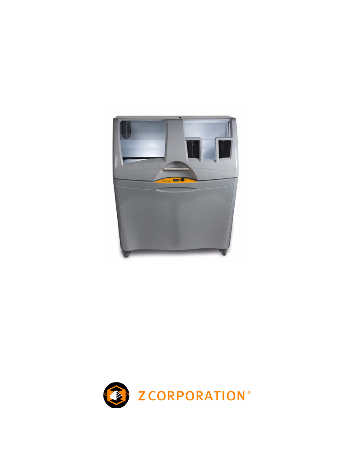
Overview Of The ZPrinter®450 Hardware Manual Chapters
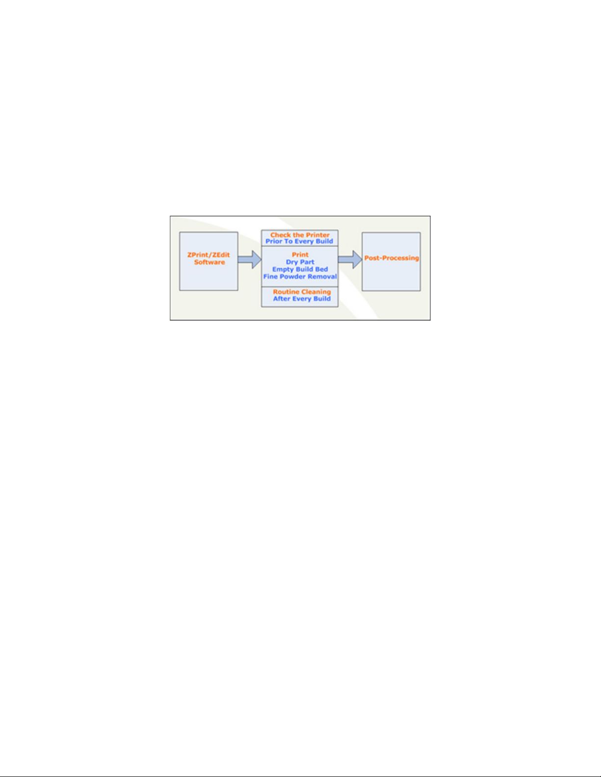
1 - ZPrinter 450 Overview. Details the ZPrinter 450 specifications and computer requirements; pro-
vides a brief overview of the principles behind 3D printing; a process diagram; a list of important terms;
labelled diagrams of the ZPrinter 450 components and the Control Panel; a description of the printer
Accessories Kit; and where to go for more information.
2 - Setup And Print The Build. Describes the necessary steps for printing a part with step-by-step
instructions; a description of the options available for transforming a part; how to create a part fixture
and why you may need to use one; a description of the ZPrint™ Printer Status and Printing dialogs;
automatic and manual powder removal options; and how to use the fine powder removal chamber.
3 - Routine Cleaning. Guides you through simple routine cleaning the operator performs after every
build including vacuuming up excess powder, cleaning the Service Station, cleaning the Parking Caps,
and emptying the Debris Filter.
4 - Post-Processing. An overview of post-processing and how to use Z-Bond™, Z-Max™, and infil-
tration systems for part strength and finish. Provides links to information regarding different infiltration
systems, and ZShop, where you can order online the consumables you need.
5 - Additional Operations. Covers how to add powder to the printer feeder, raise the build bed plat-
form, add binder, and change a print head.
6 - Printer Maintenance. Details the periodic maintenance required for keeping your printer running
smoothly and problem-free. Includes steps for lubricating the Fast Axis bearing, the Slow Axis bearing,
and the Piston Screw; changing the Binder Waste Tray; cleaning the Alignment Sensor Window;
checking the Cleaning Fluid; and printer storage preparations.
7 - Troubleshooting. References the online Help Troubleshooting Guide for common errors.

www.3dpuser.com i All Rights Reserved
10/2/07
ZPrinter®450
Hardware Manual
TABLE OF CONTENTS
1 ZPrinter 450 Overview .................................................................................... 1
1.1 New Features ........................................................................................... 1
1.2 Specifications............................................................................................ 1
1.3 Recommended Computer/System Requirements .................................... 2
1.4 How 3D Printing Works............................................................................. 3
1.5 3D Printing Process Diagram ................................................................... 4
1.6 Important Terms ....................................................................................... 4
1.7 ZPrinter 450 Components......................................................................... 6
1.8 ZPrinter 450 Rear View Diagram.............................................................. 7
1.9 Electronics Box Ethernet Connector......................................................... 8
1.10 Service Station........................................................................................ 8
1.11 Parking Caps .......................................................................................... 8
1.12 Carriage, Print Heads, and Pogo Pins.................................................... 9
1.13 LCD Menu And Control Knob (LCD Panel) ............................................ 9
1.14 LCD Menu Overview............................................................................... 9
1.15 Accessories Kit ....................................................................................... 10
1.16 Where To Go For More Information........................................................ 10
2 Setup And Print The Build ............................................................................. 12
2.1 Overview To Printing Speed, Part Strength, And Part Accuracy .............. 12
2.2 Overview To Part Orientation ................................................................... 12
2.2.1 Parts Containing an Opening or Hollow Area ................................... 13
2.2.2 Parts Containing Overhangs............................................................. 13
2.2.3 Parts Containing Cylindrical Features .............................................. 14
2.3 ZPrint/ZEdit Installation............................................................................ 14
2.3.1 ZEdit ................................................................................................. 14
2.4 Open A Part In ZPrint ............................................................................... 14
2.5 ZPrint Main Window.................................................................................. 15
2.6 Check Or Change The Default Printer Settings........................................ 16
2.7 Check The Default Powder Settings......................................................... 17
2.7.1 Create A New Powder Type ............................................................. 18
2.8 Transform The Part in ZPrint .................................................................... 18
2.9 Fixtures ..................................................................................................... 20
2.9.1 Create a Fixture for an entire part:.................................................... 20
2.9.2 Create a Fixture for a portion of a part:............................................. 21
2.10 Check the Build Layers for Errors or a Collision ..................................... 22
2.11 Check The Build Settings ....................................................................... 23
2.12 Prepare the Build Area ........................................................................... 23
2.13 Print the Build ......................................................................................... 24
2.14 Dry The Part ........................................................................................... 26
2.15 Automatic Powder Removal ................................................................... 26
2.16 Fine Powder Removal ............................................................................ 27
2.17 The Next Step......................................................................................... 28

www.3dpuser.com ii All Rights Reserved
10/2/07
3 Routine Cleaning ............................................................................................ 29
3.1 Vacuum Excess Powder........................................................................... 29
3.2 Empty The Debris Filter ............................................................................ 30
3.3 Clean The Parking Caps........................................................................... 30
3.4 Clean The Service Station ........................................................................ 31
4 Post-Processing ............................................................................................. 33
4.1 Using Z-Bond™ CyanoAcrylate................................................................ 33
4.2 Using Z-Max™ Epoxy............................................................................... 34
4.3 Using Paraplast X-TRA Wax .................................................................... 36
5 Additional Operations .................................................................................... 37
5.1 Change Print Head(s) ............................................................................... 38
5.2 Add Or Change Binder ............................................................................. 40
5.3 Add Powder To The Feeder ..................................................................... 41
5.4 Build Piston (Build Bed) ............................................................................ 41
5.5 Cover ........................................................................................................ 41
6 Printer Maintenance ....................................................................................... 42
6.1 Fast Axis Bearing Lubrication ................................................................... 42
6.2 Slow Axis Bearing Lubrication .................................................................. 44
6.3 Piston Screw Lubrication .......................................................................... 45
6.4 Change The Waste Tray........................................................................... 46
6.5 Check the Wash Fluid Level ..................................................................... 47
6.6 Clean The Alignment Sensor Window ...................................................... 47
6.7 Clean the Fast Axis Bumpers ................................................................... 48
6.8 Bleed Air ................................................................................................... 48
6.9 Printer Storage Preparation ...................................................................... 50
7 Troubleshooting ............................................................................................. 51
7.1 Service Contact ................................................................................... 52

ZPrinter®450 Hardware Manual ZPrinter 450 Overview
www.3dpuser.com 1 All Rights Reserved
10/2/07
1 ZPrinter 450 Overview
Welcome to the exciting world of 3D Printing with our newest 3D Printer, the ZPrinter 450. The ZPrinter
450 incorporates many new features that automate and streamline the 3D printing process. The full-color
capability, an easy-to-use, quiet, office-friendly design, combined with high-performance composite materi-
als, makes ZPrinter 450 the fastest, most cost-effective 3D printer available today for rapid prototyping.
This manual will instruct you on how to take care of your printer and give you an introduction to 3D Printing.
In addition, you can find information about 3D printing and its many applications and techniques on our
3DP User Group Website at www.3dpuser.com. This Website is tailored to both beginner and advanced
customers. We recommend that you register immediately to receive free, unlimited access to this excellent
resource.
1.1 New Features
• Automated Powder Loading/Removal/Recycling
• Quick-Load Binder Cartridge
• New, Single Print Head Color Technology
• Expanded On-Printer Controls
• Automatic Powder Removal
• Integrated Fine-Powder Removal Chamber
• Full-Color Capability
1.2 Specifications
Printer Dimensions and Type • With top cover closed: 48” wide x 31” deep x 55”
high. (122cm wide x 79cm deep x 140cm high)
• With top cover open: 48” wide x 31” deep x 72.3”
high. (122cm wide x 79cm deep x 183cm high)
• Floor standing model on four casters. The front two
casters are lockable.
• Full color capability; Color Shell Thickness =.025”.
• Integrated powder removal and vacuum units.
Printer Weight 425 lbs., 193 kgs.
Workstation Compatibility Windows®2000 Professional; Windows XP®Profes-
sional; Windows Vista™ 32-bit.
Network Connectivity TCP/IP 100/10 Base T.

ZPrinter®450 Hardware Manual ZPrinter 450 Overview
www.3dpuser.com 2 All Rights Reserved
10/2/07
1.3 Recommended Computer/System Requirements
• Windows®2000 Professional; Windows XP®Professional; and Windows Vista™ 32-bit Operating
Systems
Operating Environment
• Ambient Temperatures
• Ambient Relative Humidity
Maximum Temp. Range: 50-85°F (10 - 29.4° C).
Recommended Temp.Range: 55-80°F (12.7 - 26.6° C).
Maximum RH Range: 15 - 70%, non-condensing.
Recommended RH Range: 20 - 60%, non-condensing.
(May experience sub-optimal performance at extremes.)
Build Volume 8” x 10” x 8” (203 mm x 254 mm 203 mm).
640 cubic inches build capacity.
Build Speed 2-4 layers per minute.
Layer Thickness .0035” - .004” (.089 - .102 mm).
Color Shell Thickness .025”
Resolution 300 x 450 dpi print resolution.
Noise Levels During Printing = 57dB
Emptying Overflow = 66dB
Vacuuming - Cover Open = 86dB
Fine Powder Removal = 80dB
CSA, CE Approval Meets CE certification standards and UL standards.
Power Requirements 100V, 14.4 Amp.
115V, 14.0 Amp.
230V, 6.2 Amp.
Note: Due to high amperage, a dedicated outlet is
strongly recommended.
Materials - High Performance Com-
posite
zp130 Powder/zb59 Binder.
Dimensional Tolerances Parts printed with High Performance Composite materials
can be reliably printed to be within +/- 1.0% or +/- 0.005”
dimensional tolerance.
Printheads HP11 (clear binder) and HP57 (single tricolor CMY print-
head).
Liquid Waste System None. Evaporative Waste System.

ZPrinter®450 Hardware Manual ZPrinter 450 Overview
www.3dpuser.com 3 All Rights Reserved
10/2/07
• 3.2GHz processor or better (recommended)
• 2GB RAM or better (strongly recommended)
• True Color Graphics
• 64 MB Video Card, or better
• 1024 X 768 pixels, or better
• 16-bit or better with graphics card accelerated for OpenGL
• 1GB free space
• Ethernet 100/10 Base T
These system configurations may require a higher performance computer based on file size and type.
For more information, please contact your local Reseller, or visit our Website at www.3dpuser.com.
1.4 How 3D Printing Works
The 3D Printing System is based on the Massachusetts Institute of Technology's patented 3DP™ Technol-
ogy (3D Printing). The 3D Printing process requires:
• A 3D Printer
• Importing a solid 3D modeling file into the ZPrint Software
• Setting up your files to print in the ZPrint/ZEdit Software
• Printing, powder removal, and drying the part
• (Optional) Applying post-processing materials to the printed part
To start, the ZPrint Software takes a three-dimensional design file, (ZPrint is compatible with most 3D mod-
eling software files) and converts it into cross-sections, or layers, that are between 0.0035" - 0.004" (0.089
- 0.102 mm) thick. Before printing, ZPrint evaluates the part geometry and checks if there are enough
materials in the printer to print the number of layers required to build the part. If there are, the printer then
prints each layer, one after the other, from the bottom of the part to the top. If not, ZPrint will prompt you to
add powder, to add binder, or to change a print head before it will start the print job.
During printing, binder is first applied with a higher saturation to the edges of the part, creating a strong
"shell" for the part exterior. Next, an infrastructure that works like strong scaffolding is created for the part
walls, which are also built with a higher saturation of binder for added strength. The remaining interior
areas are printed with a lower binder saturation, which gives the part its stability.
When the part is finished printing, the printer heats up to the appropriate temperature and dries the part
while it is still in the Build Bed surrounded by powder. When the drying cycle is finished, an automatic pow-

ZPrinter®450 Hardware Manual ZPrinter 450 Overview
www.3dpuser.com 4 All Rights Reserved
10/2/07
der removal cycle empties the Build Bed of most of the excess powder around the part, and returns that
powder to the Feeder for reuse. After the bulk of the powder removed, the part is moved from the Build
Bed to the integrated Fine-Powder Removal Chamber where any remaining powder is cleaned off the part.
After the part is powder-free, it is ready to be removed from the printer. You can evaluate the part as it is, or
you can choose to post-process the part with infiltration products to give it additional strength, durability,
and color vibrancy. With the finished part in your hands, you can start improving or modifying your design
within the same day, and usually within hours.
1.5 3D Printing Process Diagram
1.6 Important Terms
Air Wand - The tool located in the Fine-Powder Removal Chamber that supplies air pressure. Use this tool
to remove all remaining powder from a part after the initial (automatic or manual) powder removal.
Alignment Sensor Window - Located on the underside of the Carriage unit. Wipe powder off of the Align-
ment Sensor Window every time you replace a print head, or whenever you remove a print head to clean
the contacts.
Binder - Solution that is dispensed through the HP11 print head and applied to the powder. The binder sat-
uration value will vary depending on the part geometry. The ZPrint software uses a default core and shell
saturation value that is suitable for most part geometries.
Build Bed - The 8” x 10” x 8” area in front of the Feeder where the part is printed. The platform of the Build
Bed can be raised or lowered using the appropriate command on the printer LCD menu. Before each build,
the printer fills the Build Bed with powder and then spreads a layer of powder to ensure the surface of the
Build Bed is completely smooth.
Build Chamber - The left, interior side of the printer that houses the Build Bed, Service Station, Parking
Caps, the Debris Filter, the Carriage, the Gantry assembly, the Vacuum Hose, the Heater Vent, and the
Feeder.
Carriage - Assembly that houses the Print Heads, Pogo Pin Connectors, and the Alignment Sensor Win-
dow.
Consumables - Powder-Binder-Infiltrant products that are available in a variety of systems for all of your
color or monochrome modeling needs. All consumables have been developed for the fastest printing
speeds and lowest materials costs.

ZPrinter®450 Hardware Manual ZPrinter 450 Overview
www.3dpuser.com 5 All Rights Reserved
10/2/07
Debris Filter - Located above the Heater Vent in the Build Chamber. Its function is to prevent chunks of
particles from going back into the printer Feeder during any vacuuming operation.
Deck - Area surrounding the Build Bed.
Depowder - Process of removing excess powder from a newly printed part. First, there is the initial (auto-
matic or manual) powder removal process, which removes the bulk of the powder after the part is dried in
the Build Bed. After the initial powder removal, there is the fine-powder removal process - which cleans the
part of all remaining powder.
Feeder - Printer component that stores powder. Powder that is vacuumed up after a build, or powder that
is automatically (or manually) emptied from the Build Bed, is recycled and returned to the Feeder for reuse.
Fine-Powder Removal Chamber - The right, interior side of the printer that houses the Glovebox and the
Air Wand. Printed parts are moved from the Build Bed to the Fine-Powder Removal Chamber for final
removal of any powder left on the part.
Gantry - Printer component that houses the Carriage and the Fast Axis rails that the Carriage moves on.
The Gantry moves on the Slow Axis rails which are housed beneath the Build Chamber Deck.
Glovebox - Storage space located inside the Fine-Powder Removal Chamber. Use the Glovebox to store
your printer accessories and manuals.
Heater Vent - Located directly below the Debris Filter. The Heater Vent supplies heat to the Build Chamber
during the warm-up cycle, and during the drying cycle.
Infiltration - Process of applying various post-processing products (resins, wax, epoxy, etc.) to fully
depowdered parts to give them specific properties such as strength, durability, and color vibrancy.
LCD - Liquid Crystal Display.
Parking Caps - Printer component that prevents the print heads from drying out between print jobs. It is
important to clean the Parking Caps after every build.
Platform - The bottom, metal plate of the Build Bed. The platform contains numerous small holes that
allow excess powder to escape through the bottom of the Build Bed during initial (automatic or manual)
powder removal. The platform can be raised or lowered by selecting the appropriate command on the
printer LCD menu.
Pogo Pins - Gold contact pins for the print head contacts. Clean the Pogo Pins with an alcohol swab
whenever a print head is removed, cleaned, or replaced.
Powder - Very fine particles that are not bound together. Powder is spread layer by layer and saturated
with binder to create a solid object.
Powder Screen - Located behind the Debris Filter, the round powder screen prevents any large pieces of
debris from entering the Feeder.
Print Head - There are two for the ZPrinter 450. One (HP57) for color inks (CMY), and one (HP11) for
clear binder. When a new HP11 print head is installed, the printer runs an automatic purge cycle to clean
the print head of its ink and to prepare it for dispensing binder.
Print Head Contacts - The contact points on a print head cartridge that match up with the Pogo Pins.

ZPrinter®450 Hardware Manual ZPrinter 450 Overview
www.3dpuser.com 6 All Rights Reserved
10/2/07
Purge - Process of removing ink from the HP11 print head to prepare it for dispensing binder.
Service Station - Cleans the print head jets to remove powder residue during printing. It is extremely
important to clean the Service Station after every build to remove residue buildup that gets left on the Ser-
vice Station during a build. If the Service Station is not clean, your print heads will not get properly cleaned
and this will result in premature print head expiration.
Waste Tray - Absorbs the binder waste and will require changing only when you are prompted to in ZPrint.
Located at the rear, bottom of the printer. You must remove the printer back, bottom Cover Panel to change
the Waste Tray.
1.7 ZPrinter 450 Components
ZPrinter 450 Front View ZPrinter 450 Front View With Top Cover Open

ZPrinter®450 Hardware Manual ZPrinter 450 Overview
www.3dpuser.com 9 All Rights Reserved
10/2/07
1.12 Carriage, Print Heads, and Pogo Pins
Carriage Open With Print Heads With Print Heads Removed
1.13 LCD Menu And Control Knob (LCD Panel)
LCD Menu and Control Knob
Control Knob Operations:
Push the Control Knob once to:
• Bring up the LCD menu.
• Select a menu item.
• Open a submenu.
• Start/Cancel/Stop a menu function.
Turn the Control Knob left or right to:
• Highlight a menu item.
• Increase or decrease the air pressure to the Air Wand during Fine-Powder Removal.
1.14 LCD Menu Overview
Main Menu
Vacuum
Depowder
Prep Build Chamber
Status Report
Printheads >
Build Chamber >
Go Online
Printheads Submenu
Main Menu >
Change Printheads
Align Printheads
Purge HP11 Printhead
Build Chamber Submenu
Main Menu >
Raise Platform
Lower Platform
Spread Layer
Fill Bed
Empty Build Chamber

ZPrinter®450 Hardware Manual ZPrinter 450 Overview
www.3dpuser.com 10 All Rights Reserved
10/2/07
1.15 Accessories Kit
1.16 Where To Go For More Information
A Quick Start Guide is shipped with your printer Accessories Kit and will quickly get you printing parts. It
has pictures and simple, step-by-step instructions to guide you through a print job. If you need an addi-
tional copy of the Quick Start Guide, please visit our Website at www.3dpuser.com to view or print a pdf
version.
Manuals for the ZPrint and ZEdit Software programs are available on our Website at www.3dpuser.com in
pdf versions. Both programs include a searchable Help system and links to additional information on our
User Group Website regarding 3D applications and printing/post-processing techniques.
Learn more about the different post-processing products that are available to use with your printer, on our
User Group Website at www.3dpuser.com.
Top Level:
1 - Cleaning Fluid
2 - ZPrint/ZEdit CD
3 - Screwdriver
4 - Debris Filter
5 - Ethernet Cable
6 - Cable
Not Pictured: 3/16” Hex Key
Middle Level:
1 - Syringe
2 - Grease Gun
3 - Tubing for Syringe
4 - Pick
5 - Grease Gun Nozzle
6 - Grease Cartridge
7 - Water Bottle
Bottom Level:
1 - Soft Bristle Brush
2 - Stiff Bristle Brush
3 - Vacuum Attachment
4 - Vacuum Attachment
5 - Medium Bristle Brush
6 - Vacuum Attachment
Your kit also includes a Welcome Letter, Quick Start
Guide, and trays for transporting parts.

ZPrinter®450 Hardware Manual Setup And Print The Build
www.3dpuser.com 12 All Rights Reserved
10/2/07
2 Setup And Print The Build
2.1 Overview To Printing Speed, Part Strength, And Part Accuracy
There are three important characteristics to 3D printing that will help you print the best parts for your
intended purposes. Keeping these concepts in mind, you have the basis for becoming an expert 3D printer
operator.
•Part Placement = Printing Speed. The ZPrint Software automatically positions parts in the Build
Bed for maximum build speed by placing parts with the smallest dimension in the Z-Axis.
•Strength. The ultimate strength of an uninfiltrated part will be somewhat affected by its orientation
within the Build Bed. The part will be strongest along the X-Axis and Y-Axis and less strong along
the Z-Axis. This is because the cross sections are printed in continuous strips along the Y or the
"fast" axis (the print heads’ direction of travel); in bands across the X or the "slow" axis (the gantry
direction of travel); and in laminated layers along the Z-Axis. Once a part is infiltrated, it uniformly
takes on the strength characteristics of the infiltrating product.
•Accuracy. The accuracy of your part depends on how clean the printer is, your printer/powder set-
tings, and the materials you choose for post-processing. You can also employ features like Aniso-
tropic Scaling to adjust for expected shrinkage and bring your parts into true scale. More
information on Anisotropic Scaling can be found in the ZPrint™ Software Manual.
2.2 Overview To Part Orientation
Parts that lie in the X-Y plane will be stronger than those aligned on the Z-Axis. If a part has a particularly
delicate feature, especially one shaped like a thin rod, align that feature in the X-Y plane for the greatest
strength. If a part has particularly delicate features that are supported only by unprinted powder, build a
Fixture for the part to reduce the chances of breaking the feature during powder removal. See Section 2.9
for instructions on how to create a Fixture.

ZPrinter®450 Hardware Manual Setup And Print The Build
www.3dpuser.com 13 All Rights Reserved
10/2/07
Do not tightly pack multiple parts into the Build Bed. If multiple parts are tightly packed, it may be difficult to
lift them out of the Build Bed with proper support. If a delicate part is being built with other more solid parts,
add a Fixture to the delicate part to protect it during powder removal.
2.2.1 Parts Containing an Opening or Hollow Area
Place the hollow side of a part facing down in the Build Bed to allow powder to evacuate during powder
removal. Depending on how the part is imported into ZPrint, you may need to use the Rotate feature to
correctly orient the part. Build parts that are delicate with a Fixture, to give them extra support and addi-
tional protection during powder removal. See Section 2.9 for instructions on how to create a Fixture.
An example of a part with hollow sides facing down
2.2.2 Parts Containing Overhangs
For delicate parts and parts with overhangs, create a Fixture, or create a Fixture for the area of the part
that needs support. Unsupported overhangs are placed on the rear-most side of the Build Bed, as close to
the bottom of the Build Bed as possible. See Section 2.9 for instructions on how to create a Fixture.
An example of a part with two Fixtures to support the overhangs

ZPrinter®450 Hardware Manual Setup And Print The Build
www.3dpuser.com 14 All Rights Reserved
10/2/07
2.2.3 Parts Containing Cylindrical Features
Cylindrical features will be more accurate when the cylindrical axis is parallel to the Z-Axis.
The remainder of this chapter takes you through setting up your build in ZPrint and printing a part.
2.3 ZPrint/ZEdit Installation
If ZPrint has not been installed, you will first need to install it. Installation instructions are available in the
ZPrint™ Software Manual. Be sure to install the software on the same computer that is connected to your
3D Printer.
If you encounter any problems during installation, please contact your local Service Provider or Reseller, or
visit our Website at www.3dpuser.com.
2.3.1 ZEdit
ZEditTM is an add-on software that ships with ZPrint. ZEdit was developed by a team of software develop-
ers and application engineers as a tool to help those who use HD3DP™ (high-definition 3D printing) to
optimize their color applications. This software program works in conjunction with the ZPrint software. Use
ZEdit to apply color or labels to your part, as well as to diagnose and correct simple file problems. Color
may be applied to a part through the application of a texture map, engineering template, text, or by using
the paint features.
Customers should install ZEdit when ZPrint is installed. See the ZPrint™ Software Manual for installation
instructions. Refer to the ZEdit™ Software Manual, or the ZEdit Online Help, for specifics about using this
software.
2.4 Open A Part In ZPrint
1. Launch the ZPrint Software. The Splash screen will close on its own after a few seconds, or you
can click the OK button to immediately close the screen.
2. In the Open dialog, select a file to print, or browse to a file on your computer. Click the Open but-
ton, or double click on a file to open it in ZPrint.

ZPrinter®450 Hardware Manual Setup And Print The Build
www.3dpuser.com 15 All Rights Reserved
10/2/07
3. If the Choose Units dialog opens, choose the display units that correspond to the part dimen-
sions and then click Next. The file is opened in a new ZPrint window using the units specified in
this dialog.
4. If you would like to add additional files to the build, select File > Import and select more files. By
default, ZPrint will position each file in the Build Bed for the fastest print time.
• If you do not want ZPrint to position your part(s) for printing speed, uncheck the Orient
imported parts for the fastest times option on the Settings > General Preferences >
Import/Export tab.
2.5 ZPrint Main Window
See the ZPrint™ Software Manual for a complete description of the Main Window.

ZPrinter®450 Hardware Manual Setup And Print The Build
www.3dpuser.com 16 All Rights Reserved
10/2/07
2.6 Check Or Change The Default Printer Settings
1. Select Settings >Printer Settings to display the Default Printer Settings dialog.
2. In the Default Printer Settings dialog, check that the default printer is the printer that is connected
to your computer.
• If it is not, click Select Printer and proceed with Step 3.
• If it is, click Cancel and skip the rest of this procedure.
3. In the Select 3D Printer dialog, choose Network as the Port Type. Click the Find button to locate
the printer on the network. If the printer is connected to the network, it will appear on the list. Select
the printer and click OK.
4. The Default Printer Settings dialog reopens showing your new default settings. To save your set-
tings, click the Save As Default button. You can change these settings at any time by repeating
Steps 1 - 4.
Table of contents
Other Zcorporation 3D Printer manuals

Zcorporation
Zcorporation Z 406 User manual

Zcorporation
Zcorporation ZPrinter 650 User manual

Zcorporation
Zcorporation ZPRINTER 310 PLUS User manual

Zcorporation
Zcorporation SPECTRUM Z M510 User manual

Zcorporation
Zcorporation Spectrum Z 510 User manual

Zcorporation
Zcorporation ZPrinter 310 User manual

Zcorporation
Zcorporation Z402C User manual

Zcorporation
Zcorporation ZPrinter 310 User manual

Zcorporation
Zcorporation zprinter 450 User manual

Zcorporation
Zcorporation Z 406 User manual