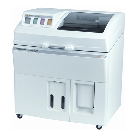
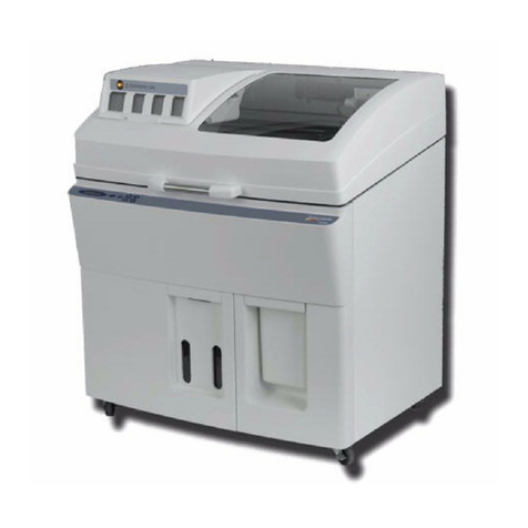
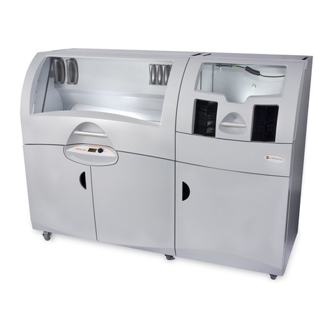
Zcorporation Z810 User manual

Z810 System User Manual
January 2004
Copyright © 2002-2004 Z Corporation Rev. F, Part Number 09505
Z®810 Color 3D Printer User Manual

Z Corporation Z810 System User Manual
www.zcorp-users.com 2
TABLE OF CONTENTS
1INTRODUCTION.......................................................................................................................7
1.1 OVERVIEW .......................................................................................................................... 7
1.2 HOW IT WORKS .................................................................................................................... 8
2SYSTEM COMPONENTS.......................................................................................................11
2.1 Z810 PRINTER COMPONENTS............................................................................................ 11
2.1.1 Z810 3D Printer........................................................................................................ 11
2.1.1.1 Z810 Carriage Assembly...................................................................................... 14
2.1.1.2 Z810 Service Station............................................................................................ 15
2.1.1.3 Z810 Rear Connector Panel ................................................................................ 16
2.1.1.4 Z810 Printer Control Panel................................................................................... 17
2.1.2 ZF8 Powder Feeder................................................................................................. 18
2.1.2.1 ZF8 Rear Connector Panel .................................................................................. 19
2.2 ZD8 DEPOWDERING UNIT.................................................................................................. 20
2.2.1 Air Curtain................................................................................................................ 22
2.2.2 ZD8 Control Panel ................................................................................................... 23
2.2.3 Powder Collection Drawer ....................................................................................... 24
2.2.4 ZD8 Cart .................................................................................................................. 24
2.3 DESPATCH LBB FORCED CONVECTION OVEN (OPTION)...................................................... 25
3QUICK START GUIDE ...........................................................................................................26
3.1 PRINTER PREPARATION ..................................................................................................... 26
3.2 SETTING UP THE BUILD ...................................................................................................... 28
3.3 TRANSFERRING THE PART TO THE DEPOWDERING UNIT ...................................................... 29
3.4 DEPOWDERING THE PART.................................................................................................. 30
3.5 TRANSFER TO OVEN.......................................................................................................... 31
3.6 FINISH PART ..................................................................................................................... 31
3.7 USER TIPS ........................................................................................................................ 31
3.7.1 Set-up and Post-processing .................................................................................... 31
3.7.1.1 Part Setup, Orientation, and Print Settings.......................................................... 31
3.7.1.2 Gross and Fine Depowdering .............................................................................. 32
3.7.1.3 Oven Dry the Part................................................................................................. 32
3.7.2 Part Infiltration.......................................................................................................... 32
3.7.2.1 When Using Z-Bond Resin................................................................................... 32
3.7.2.2 When Using a Z-Snap or Z-Max Epoxy ............................................................... 32
4PREPARING THE Z810 3D PRINTER...................................................................................33
4.1 REPLACING THE BUILD PALLET........................................................................................... 33
4.2 CLEANING THE SERVICE STATION ...................................................................................... 33
4.3 GREASING THE FAST AXIS ................................................................................................. 34
4.4 OIL SLOW AXIS ................................................................................................................. 35
4.4.1 Snowplows............................................................................................................... 35
4.4.2 Slow Axis Path......................................................................................................... 35
4.5 FILL BED........................................................................................................................... 36
4.6 REMOVE POWDER FROM OVERFLOW CHUTE ...................................................................... 36
4.7 CHECKING POWDER LEVELS.............................................................................................. 37
4.8 CHECK FLUID LEVELS........................................................................................................ 38
4.8.1 Binder Containers.................................................................................................... 38
4.8.2 Check Waste Container........................................................................................... 39
4.8.3 zc3 Wash Fluid Container........................................................................................ 40
5USING ZPRINT SOFTWARE .................................................................................................41
5.1 OPEN OR IMPORT THE FILE................................................................................................ 41
5.2 ORIENTING THE PART ........................................................................................................ 41

Z810 System User Manual Z Corporation
Z Corporation Service (781) 852-5050 / (887) 88-ZCORP 3
5.2.1 Part Containing an Opening or Hollow Area............................................................ 41
5.2.2 Part Containing Overhangs ..................................................................................... 42
5.3 CHECKING BUILD SETTINGS............................................................................................... 42
5.3.1 Powder Settings....................................................................................................... 43
5.3.1.1 Anisotropic Scaling Values................................................................................... 43
5.3.1.2 Saturation Values................................................................................................. 44
5.4 PRINTING THE BUILD.......................................................................................................... 45
6REMOVING THE PART..........................................................................................................46
6.1 SET TIMES ........................................................................................................................ 46
6.2 GROSS DEPOWDERING...................................................................................................... 47
6.3 TRANSFERING THE PARTS TO THE DEPOWDERING STATION................................................. 49
6.4 POST PROCESSING TOOLS ................................................................................................ 53
7DEPOWDERING THE PART..................................................................................................55
7.1 CHANGING AIR NOZZLES ................................................................................................... 55
8INFILTRANTS.........................................................................................................................58
8.1 USING Z-MAXEPOXY......................................................................................................... 58
8.2 USING Z-BOND CYANOACRYLATE....................................................................................... 60
8.2.1 Safety Precautions................................................................................................... 60
8.2.2 General Application Notes....................................................................................... 60
8.2.3 Spraying Instructions ............................................................................................... 60
8.2.4 Curing Information ................................................................................................... 60
8.3 USING Z-SNAP EPOXY....................................................................................................... 61
8.3.1 General Application Notes....................................................................................... 61
8.3.2 Mixing Instructions................................................................................................... 61
8.3.3 Curing Information ................................................................................................... 61
8.3.4 Clean Up.................................................................................................................. 61
8.4 USING PARAPLAST X-TRA WAX......................................................................................... 62
8.4.1 Safety Precautions................................................................................................... 62
8.4.2 General Application Notes....................................................................................... 62
8.4.3 Curing Information ................................................................................................... 62
9APPLICATIONS......................................................................................................................63
9.1 GLUING MULTI-PIECED PARTS............................................................................................. 64
9.2 PAINTING PARTS ............................................................................................................... 65
9.3 POLYESTER RESIN ............................................................................................................ 66
9.4 ELECTROPLATING.............................................................................................................. 67
9.5 WATER TRANSFER PRINTING ............................................................................................. 68
9.6 INVESTMENT CASTING ....................................................................................................... 71
9.7 FLEXIBLE PARTS ............................................................................................................... 73
9.8 THERMOFORMING.............................................................................................................. 74
9.9 RTV MOLDING .................................................................................................................. 76
10 CHANGING AND ALIGNING THE PRINT HEADS............................................................82
10.1 CHANGING THE PRINT HEADS ............................................................................................ 82
10.2 ALIGNING THE PRINT HEADS .............................................................................................. 85
11 CHANGING MATERIAL SYSTEMS...................................................................................92
11.1 USING ZCAST 500 POWDER........................................................................................... 95
11.1.1 GENERAL INFORMATION ..................................................................................... 95
11.1.2 USING ZCAST ON YOUR Z810 3D PRINTER....................................................... 95
11.1.3 LOADING ZCAST INTO THE Z810 3D PRINTER.................................................. 96
11.1.4 SETTING UP ZCAST BUILDS ................................................................................ 96
11.1.5 POST PROCESSING ZCAST PARTS.................................................................... 96

Z Corporation Z810 System User Manual
www.zcorp-users.com 4
11.1.6 MATERIAL ORDERING........................................................................................... 97
11.1.7 RECYCLING............................................................................................................ 97
11.1.8 STORAGE ............................................................................................................... 97
11.1.9 DISPOSAL............................................................................................................... 97
11.1.10 QUESTIONS AND SUPPORT............................................................................. 97
11.2 USING ZP250 POWDER .................................................................................................. 98
11.2.1 Machine Setup......................................................................................................... 98
11.2.2 Software Setup ........................................................................................................ 98
11.2.3 Part Removal and Post Processing....................................................................... 100
11.2.4 Infiltration Addendum............................................................................................. 102
12 MAINTENANCE............................................................................................................... 103
12.1 CHANGE ZC3WASH FLUID............................................................................................... 103
12.2 FLUSH SYSTEM WITH DISTILLED WATER ........................................................................... 105
12.3 CLEAN UNDER GANTRY ................................................................................................... 108
12.4 OIL SLOW AXIS RAIL........................................................................................................ 109
12.5 CLEAN FAN FILTER.......................................................................................................... 109
12.6 CLEAN SPREADER ROLLER.............................................................................................. 110
12.7 CLEANING THE SQUEEGEE SQUIRTERS............................................................................. 111
12.8 BLEEDING AIR FROM THE FLUID SYSTEM.......................................................................... 112
12.9 CLEAN POWDER SCREEN ON THE ZF8 POWDER FEEDER .................................................. 113
12.10 EMPTY POWDER DRAWER ON THE ZD8 DEPOWDERING UNIT......................................... 113
13 Z810 SYSTEM DETAILS ................................................................................................. 115
13.1 SYMBOLS USED ........................................................................................................... 115
13.2 SYSTEM SPECIFICATIONS............................................................................................. 115
13.3 MATERIAL STORAGE PRECAUTIONS.............................................................................. 116
13.4 ERROR CODES................................................................................................................ 116
14 INDEX............................................................................................................................... 122
APPENDIX I – ZCAST DESIGN GUIDE……………………………………………………………...125

Z810 System User Manual Z Corporation
Z Corporation Service (781) 852-5050 / (887) 88-ZCORP 5
TABLE OF FIGURES
FIGURE 1: THE PRINTING PROCESS.................................................................................................... 8
FIGURE 2: THE SHELLING AND INFRASTRUCTURE FEATURES................................................................ 9
FIGURE 3: ILLUSTRATION OF ZCORP.SYSTEM PRINT ORIENTATIONS................................................. 10
FIGURE 4: Z810 3D PRINTER (FRONT VIEW)..................................................................................... 12
FIGURE 5: Z810 3D PRINTER (TOP VIEW)......................................................................................... 13
FIGURE 6: Z810 3D PRINTER CARRIAGE ASSEMBLY.......................................................................... 14
FIGURE 7: Z810 3D PRINTER SERVICE STATION ............................................................................... 15
FIGURE 8: Z810 3D PRINTER CONNECTOR PANEL ............................................................................ 16
FIGURE 9: Z810 3D PRINTER CONTROL PANEL................................................................................. 17
FIGURE 10: ZF8 POWDER FEEDER (FRONT VIEW)............................................................................. 18
FIGURE 11: ZF8 POWDER FEEDER REAR CONNECTOR PANEL........................................................... 19
FIGURE 12: ZD8 DEPOWDERING UNIT .............................................................................................. 21
FIGURE 13: ZD8 AIR CURTAIN SELECTOR LEVER.............................................................................. 22
FIGURE 14: ZD8 CONTROL PANEL.................................................................................................... 23
FIGURE 15: ZD8 POWDER COLLECTION DRAWER.............................................................................. 24
FIGURE 16: ZD8 CART..................................................................................................................... 24
FIGURE 17: PRINTING STATUS DIALOGUE BOX .................................................................................. 45

Z Corporation Z810 System User Manual
www.zcorp-users.com 6
Use of Equipment
The Equipment was manufactured under patents licensed to Z Corp. to be used for the
fabrication of appearance models and prototypes. Other uses may be restricted; contact Z
Corporation for further information.
The Equipment is designed to be used by design engineers and other professionals in the
production of early-stage 3D appearance models and prototypes. The Equipment is not to be
used to produce, either directly or indirectly, medical or other products that may require precise
dimensions or tolerances to ensure the safe and effective operation of such products. You agree
to indemnify, defend and hold Z Corporation and its officers, directors and employees harmless
from and against any and all claims, losses, damages, costs and expenses resulting from any
use of the Equipment other than for the production of early-stage appearance models and
prototypes.
If you have purchased all relevant casting-specific products as recommended by Z Corp.
(casting-specific service contract, hardware, software, and consumables), as well as a casting
license, then you are authorized to utilize the Equipment to fabricate molds for casting.

Z810 System User Manual Z Corporation
Z Corporation Service (781) 852-5050 / (887) 88-ZCORP 7
1 INTRODUCTION
1.1 OVERVIEW
This Z810 Color 3D Printer Manual will speed you along the path towards quickly and
inexpensively building parts. The manual contains the following sections:
1. Introduction. This section will give you an overview of the principles behind the Z Corporation
(“Z Corp.”) 3D Printer.
2. The System Components. This section will provide a guide for the Z810 System components
and features detailed diagrams. It will describe the Z810 3D Printer (“Printer”), ZF8 Powder
Feeder (“Feeder”), the ZD8 Depowdering Unit (“Depowderer”), and the optional oven.
3. Quick Start Guide. This section will give you a quick breakdown of steps needed to print your
part.
4. Preparing the Z810 3D Printer. This section will guide you through the steps for preparing the
Z810 3D Printer. It includes checking the powder, and fluid levels as well as maintenance
procedures such as lubricating the axes and cleaning the service station.
5. Using ZPrint Software. This section takes you through a few basics of how to set up your
build in ZPrint Software (also referred to as software). For more details on the features
available in the Software, please refer to the ZPrint Software User Manual.
6. Removing the Part. This section will guide you through removing your part from the Printer
and transferring it to the ZD8 Depowdering Unit.
7. Depowdering the Part. This section will guide you through using the ZD8 Depowdering Unit.
8. Infiltrants. This section offers some recommendations on which infiltrants to use and how to
apply them to your part.
9. Applications. This section will teach you various ways to maximize the versatility of your
printer through the implementation of advanced part processing techniques.
10. Changing and Aligning Print Heads.This section contains detailed instructions on how to
change and align the HP Print Heads in the Z810 3D Printer.
11. Changing Material Systems. This section contains detailed instructions on how to use
specific powder sytems.
12. Maintenance. This section contains recommended periodic maintenance procedures.
13. Z810 System Details. This section contains system specifications about the Z810 3D Printer.

Z Corporation Z810 System User Manual
www.zcorp-users.com 8
1.2 HOW IT WORKS
The Z Corp. Printer Systems are based on the Massachusetts Institute of Technology’s patented
3DP™(3D Printing) technology.
The ZPrint Software first converts three-dimensional data from CAD, or other sources into cross-
sections or slices that can be between 0.0035” – 0.009” thick. The Z810 3D Printer then prints
these cross-sections one after another from the bottom of the part to the top.
Inside the Z810 3D Printer there is a build piston, where the part is built (see Figure 1). Also
represented in the diagrams are the roller, print heads, build area, and cleaning area. The roller
moves horizontally across the build area.
When beginning the 3D printing process, the printer first spreads a layer of powder in the same
thickness as the cross section to be printed. The print heads then apply a binder solution to the
powder causing the powder particles to bind to one another and to the printed cross-section one
level below. The build piston descends one layer thickness. The roller then spreads a new layer
of powder and repeats the process, until the entire part is printed.
Figure 1: The Printing Process

Z810 System User Manual Z Corporation
Z Corporation Service (781) 852-5050 / (887) 88-ZCORP 9
The Z Corp. Printer System employ several techniques to quickly build parts. First, binder
solution is applied in a higher concentration around the edges of the part, creating a strong “shell”
around the exterior of the part. Within parts, the Z Corp. 3D Printer builds an infrastructure by
printing strong scaffolding within part walls with a higher concentration of binder solution. The
remaining interior areas are printed with a lower saturation, which gives them stability, but
prevents over-saturation, which can lead to distortion of the part.
Figure 2: The Shelling and Infrastructure Features
After printing, the part is removed from the powder bed, dried, and depowdered. The part can
then be infiltrated with wax, epoxy, or other materials to increase strength and durability. More
information on different infiltrants can be found in Section 8, Infiltrants.
There are several important issues to consider when preparing a build that will help you print the
best parts for your intended purpose.
Part Placement. The ZPrint Software will place the parts within the build box to maximize build
speed, the most important criteria for the majority of our users. The ZPrint Software positions the
parts with the smallest dimension in the z (vertical) axis. For more information, refer to the ZPrint
Software User Manual.
Strength. The ultimate strength of the part will be somewhat affected by its orientation within the
print box. The part will be strongest along the x-axis and the y-axis and less strong along the z-
axis. This is because the cross sections are printed in continuous strips along the y or the “fast”
axis (the print heads direction of travel), bands across the x or the “slow” axis (the gantry direction
of travel) and laminated layers along the z-axis.
Exterior walls
printed at higher
saturation.
Interior infrastructure
printed at a higher
saturation
Other interior areas
printed at lower
saturation

Z Corporation Z810 System User Manual
www.zcorp-users.com 10
Figure 3: Illustration of Z Corp. System Print Orientations
Accuracy. The accuracy of the printer depends on the materials you choose and the offset and
scaling factors used. You can employ the anisotropic scaling feature in the software to adjust for
expected shrinkage and bring your parts into true scale. More information on anisotropic scaling
factors can be found in Section 5.3.1.1, Anisotropic Scaling Values.
z-axis
x-axis
y-axis
Strongest
Less Strong
Stron
g

Z810 System User Manual Z Corporation
Z Corporation Service (781) 852-5050 / (887) 88-ZCORP 11
2 SYSTEM COMPONENTS
2.1 Z810 PRINTER COMPONENTS
The Z810 System consists of the following hardware components:
2.1.1 Z810 3D PRINTER
Site Requirements:
Power: 100-240 VAC, 50-60 Hz
Compressed Air: Clean, dry air (dew point 40oF/4oC or below)
Air Fitting: ¼ “Industrial” quick disconnect or other quick disconnect with ¼ inch NPTM pipe thread
Dimensions: 46.5 inches (1.18 meters) deep x 64.5 inches (1.64 meters) wide x 54.5 inches (1.38 meters) tall
(with top cover closed); 111 inches (2.82 meters) tall with top cover open.
PLEASE NOTE: Left to right (width) dimensions are not additive for the System because
the printer and powder feeder overlap by several inches when the feeder is docked.

Z Corporation Z810 System User Manual
www.zcorp-users.com 12
Top Cover
zc3 Wash Fluid
Container
Overflow Vacuum
Receptacle
Overflow Chute
Electronics
Enclosure
Pump
Enclosure
Waste ContainerClear Binder Container
Color Binder
Container (Cyan,
Magenta, Yellow)
Control Panel
Top Cover
Handle
ZF8 Powder
Feeder
Power Switch
Figure 4: Z810 3D Printer (Front View)

Z810 System User Manual Z Corporation
Z Corporation Service (781) 852-5050 / (887) 88-ZCORP 13
Carriage
Print Heads
Removable
Build Pallet
Spread Roller
Overflow Chute
Service Station
Print
Head Spit
Area
Top Deck
Gantry -
Moves along
the slow axis
Printer Assembly -
Rests on the Gantry
Figure 5: Z810 3D Printer (Top View)

Z Corporation Z810 System User Manual
www.zcorp-users.com 14
2.1.1.1 Z810 Carriage Assembly
Carriage Cover
Carriage Cover Latch
Note: One is located
in the back of the
carriage (not shown)
Print Heads
(Numbered
from 0-5 from
front to back)
0
1
2
3
4
5
Figure 6: Z810 3D Printer Carriage Assembly

Z810 System User Manual Z Corporation
Z Corporation Service (781) 852-5050 / (887) 88-ZCORP 15
2.1.1.2 Z810 Service Station
Print Head Spit Area
Wash Fluid
Spray Nozzle
Squeegees
Print Head
Parking Cap
Figure 7: Z810 3D Printer Service Station

Z Corporation Z810 System User Manual
www.zcorp-users.com 16
2.1.1.3 Z810 Rear Connector Panel
Power Input
- Connector
provided
Powder Feeder Serial
Cable - Connector
provided
Diagnostic Video
Connector - No
connector provided
Serial Input
Connection -
Connector provided
Network
Connection -
Connector
provided
Diagnostic Keyboard
Connector - No
connector provided
Circuit Breaker
Power Entry
Module
Air Connector
- Connecting
hose provided
Detailed Diagram
Figure 8: Z810 3D Printer Connector Panel

Z810 System User Manual Z Corporation
Z Corporation Service (781) 852-5050 / (887) 88-ZCORP 17
2.1.1.4 Z810 Printer Control Panel
LCD Panel.
Displays the
current status
of the Z810
3D Printer.
Online Button.
Enables and disables
printer communication.
Spread Button. This button moves the
gantry from left to right allowing the user
to spread powder over the build piston.
Fill Bed.
Prepares build
area for
printing by
spreading
powder over
the build area.
Load/Unload.
Lifts build piston
to allow for pallet
placement and
removal.
Build Up/Down Buttons.
Allows the user to raise or
lower the build piston.
Briefly pressing this button
raises or lowers one layer
thickness; holding down
causes continuous motion.
Figure 9: Z810 3D Printer Control Panel

Z Corporation Z810 System User Manual
www.zcorp-users.com 18
2.1.2 ZF8 POWDER FEEDER
Site Requirements:
Power: Voltage : 100VAC, 50/60Hz, 20A
115VAC, 50/60Hz, 17A
230VAC, 50/60Hz, 10A
Compressed Air: Clean, dry air (dew point 40oF/4oC or below)
Air Fitting: ¼ “Industrial” quick disconnect or other quick disconnect with ¼ inch NPTM pipe thread
Dimensions: 31 inches (0.79 meters) deep x 32 inches (0.81 meters) wide x 78 inches (1.98 meters)
tall.
Vacuum Hose Receptacles. The
vacuum hose connects to these
receptacles to allow for loading
powder from container, vacuuming
up powder from the build area,
emptying the overflow chute, and
emptying the ZD8 Powder Drawer.
Access Panel. Allows
access to the ZF8
Screen which screens
out powder chunks
from being deposited
into the powder.
Vacuum Hose and
Attachment Storage.
Holds vacuum hose and
all attachments for easy
access and storage.
Handle. Allows
user to remove
Powder Feeder
when changing
material systems.
Vacuum Switch. Turns
vacuum on and off.
Figure 10: ZF8 Powder Feeder (Front View)

Z810 System User Manual Z Corporation
Z Corporation Service (781) 852-5050 / (887) 88-ZCORP 19
2.1.2.1 ZF8 Rear Connector Panel
Air Connector -
Connecting Hose
provided
Power Input -
Connector
provided
Power Switch
Powder Feeder
Serial Cable -
Connector provided
Figure 11: ZF8 Powder Feeder Rear Connector Panel

Z Corporation Z810 System User Manual
www.zcorp-users.com 20
2.2 ZD8 DEPOWDERING UNIT
Site Requirements:
Power: Voltage: Receptacle For Plug Type :
190-200 VAC, 50Hz, 10.5A IEC 60309-2: RED-6h-32A-3p+N+E
208-230 VAC, 60Hz, 15A IEC NEMA L15-30 Plug
380-400 VAC, 50Hz, 5.3A IEC 60309-2 Plug, Red-6h-16A-3p+N+E Plug
Compressed Air: Clean, dry air (dew point 40oF/4oC or below)
Air Fitting: ¼ “Industrial” quick disconnect or other quick disconnect with ¼ inch NPTM pipe thread.
Requires a ¼ NPTM mate.
Dimensions:
46 inches (1.17 meters) deep x 40 inches (1.02 meters) wide x 105 inches (2.67 meters) tall.
Ceiling clearance of 120 inches (3 meters) is needed to upright the Depowdering Unit from
shipping orientation.
Table of contents
Other Zcorporation 3D Printer manuals

Zcorporation
Zcorporation Z402C User manual

Zcorporation
Zcorporation Spectrum Z 510 User manual

Zcorporation
Zcorporation ZPrinter 450 User manual

Zcorporation
Zcorporation SPECTRUM Z M510 User manual

Zcorporation
Zcorporation ZPrinter 310 User manual

Zcorporation
Zcorporation ZPrinter 650 User manual

Zcorporation
Zcorporation Z 406 User manual

Zcorporation
Zcorporation ZPRINTER 310 PLUS User manual

Zcorporation
Zcorporation Spectrum Z 510 User manual

Zcorporation
Zcorporation D4 User manual