Zummo Z40 Owner's manual

011307-05 1
Technical Instructions
Z
40
INDEX:
1.- Error list.
2.- Disassemble machine.
3.- Dismantling of motor and gear box in Z40.
4.- Assembly of gear box in Z40
5.- Adjustment of pushing plate.
6.- Replacement of cup shaft fixing ring.
7.- Replacement of cup shaft.
8.- Replacement of ball bearing.
9.- Machine setup levels.
10.- Circuit diagram in Z40
11.- Feeder synchronization checking.
12.- Machine closing.
1.- ERROR LIST
1.1 Front cover not fitted correctly.
The display will show the following image:
The front cover has a magnet attached on the top. Once fitted in its position, the sensor placed
inside the hopper track base closes the safety circuit. The error message will then disappear,
allowing you to operate the machine.
1.1.1 Check that the magnet is on the front cover. If not there, replace the front cover.
1.1.2 If the magnet is on the front cover, disassemble the hopper track lid following the instructions
to open the machine from step #2. Once open, check there is electric continuity between

011307-05 2
Technical Instructions
Z
40
both connector terminals, with the help of a multimeter. If there is no continuity, you must
change the magnet sensor.
2
2.1.1 If the magnet is on the front cover and there is continuity between the sensor terminals with
the front cover in place, you must change the circuit board.
1.2 Side covers not fitted correctly.
The display will show the following image:
The side covers trigger two micro-switches that, once pushed, close the safety circuit and make the
error message on the display disappear. These micro-switches are normally used with the contact
configuration in open position.
1.2.1 Check that, when pushed with your fingers, you can hear the “click” of the micro-switch
opening and closing. If not the case, disassemble the front, following the instructions from step #2
and check they are not broken. If any is broken, proceed to replace it.

011307-05 3
Technical Instructions
Z
40
1.2.2 If you can hear the “click” but they do not close the safety circuit, disassemble the hopper
track lid (follow instructions in step #2 to open the machine) and check if there is conductivity
between pins 4 and 10 with the side covers correctly placed.
If there is no conductivity, check which of the micro-switches is causing the failure.
If there is conductivity, the failure is being caused by the circuit board and you must replace it.
1.3 Filter tray/self-service filter/tank not fitted correctly.
The display will show the following image:
Underneath the squeezer tray, on the right side, there is a safety switch. If it is not triggered, the
machine will be temporarily out of order, showing the above error message. This switch triggers a
micro-switch like the one used on the side covers.

011307-05 4
Technical Instructions
Z
40
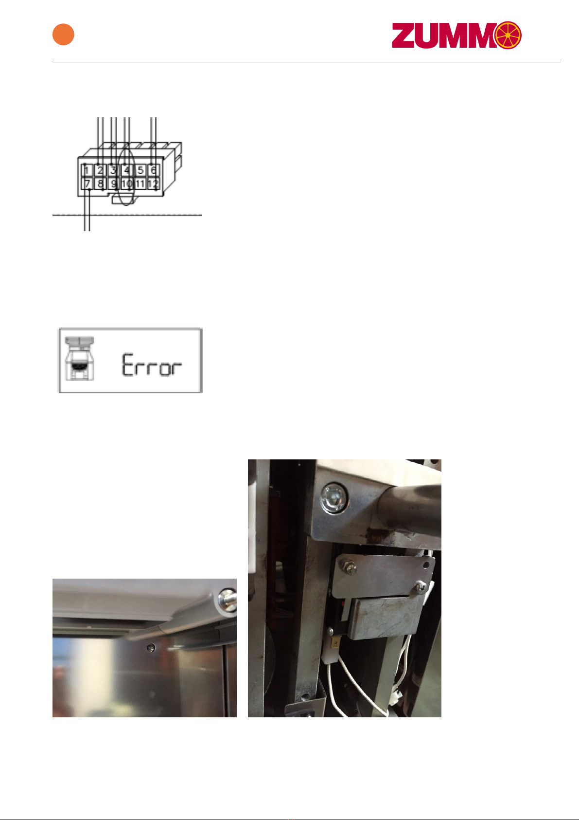
In the same way as before, pushing the switch with your fingers, you should be able to hear the
opening and closing “click”.
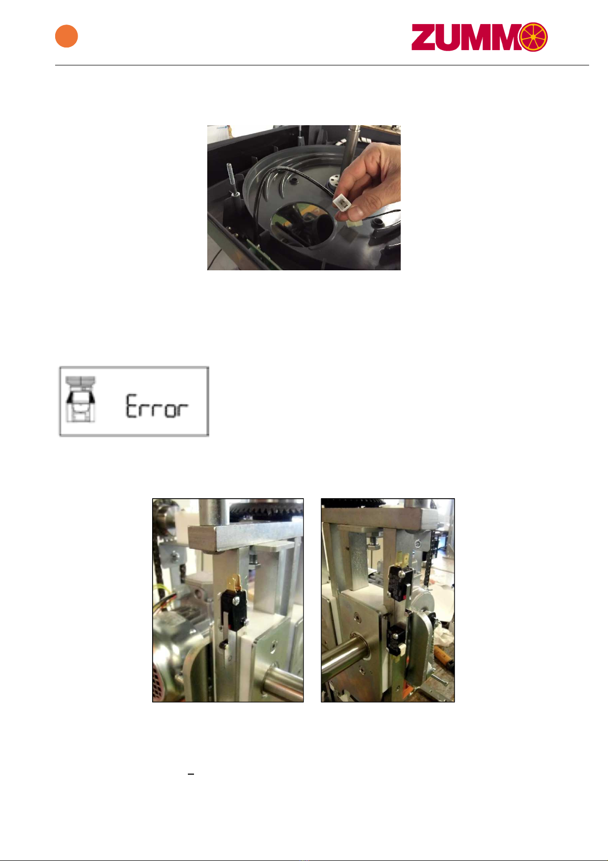
If this error is shown while working, check that filter tray, self-service tray and tank are all correctly
placed as they could have moved from its original position. In this case, check the condition of the
pieces. They must not be deformed.
If this error is shown when the machine is stopped, check the following:
1.3.1 Check you can hear the opening and closing “click” of the micro-switch when pushed using
your fingers. If not the case, disassemble the front, following the instructions from step #2 and check
they are not broken. If any is broken, replace it. Check connections.
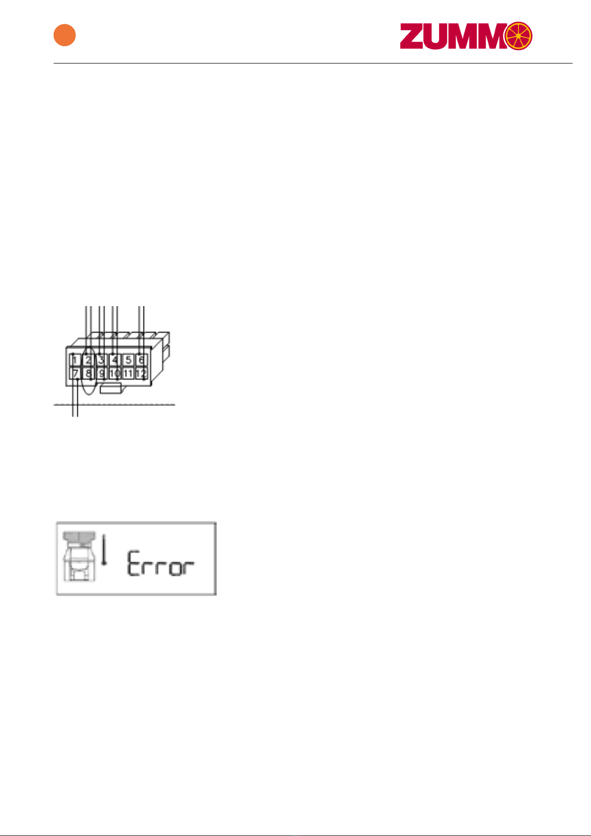
1.3.2 If you can hear the “click” but they do not close the safety circuit, disassemble the hopper
track lid (follow instructions in step #2 to open the machine) and check if there is conductivity
between pins 2 and 8 with the filter tray properly fitted.
If there is no conductivity, change the micro-switches.
If there is conductivity, the failure is being caused by the circuit board and you must replace it.
1.4 Motor thermal sensor.
The display will show the following image:
The motor contains, in the stator coil winding, a thermal sensor that opens at 105ºC (221º F). When
the motor temperature reaches that value, the sensor opens the safety circuit; the display will then
show an error and leaves the machine temporarily out of order. After a few minutes, once the motor
temperature has dropped down to an acceptable value, the error message will disappear and the
machine will become operative again, without having to unplug it from the main power.
The reason can be:
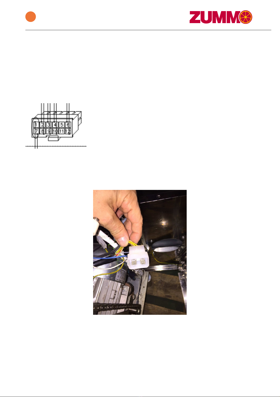
- The fan placed in the main body does not work; hence it does not cool down the motor.
Check fan connections. If properly plugged in, check the tension arriving to connectors
(between 110-240 volts AC depending on versions). If tension arriving and fan still not
working, change the fan.

011307-05 5
Technical Instructions
Z
40
- The squeezer tray balls are not fully screwed and the motor is then subject to a bigger effort.
Check by sight and manually.
- The squeezer tray balls do not match the cup size.
- The cooling grill is being partially or completely blocked by any object.
If the motor temperature seems not to be the reason of this error message when the machine is
cold or the error message does not disappear once the machine has cooled down, check the
following points:
1.4.1 Disassemble the hopper track lid following the instructions from step #2 and check there is
continuity between pins 1 and 7 of main connector.
If there is continuity and the motor is cooled down, you should change the circuit board.
If there is no continuity on this connector, we will proceed to check continuity between yellow cables
of the motor connector.
- If there is no continuity with the motor cooled down, you should change the motor.
- If there is continuity, the issue must be located within the main wiring, and you should change it.

011307-05 6
Technical Instructions
Z
40
1.5 Cycle failure
The display will show the following image:
The machine completes a cycle (a piece of fruit) every 1.5 seconds. Within this period of time, a
signal is sent to the circuit board via a micro-switch that is triggered (opening and closing) by the
right cup slide. If, for any reason, the circuit board does not receive any signal from this micro-switch
within 4 seconds, the circuit board will cut off the signal arriving to the motor due to safety reasons,
and an error message will be then shown on the display.
The reasons this error is shown may be:
1.5.1 Micro-switch failure.
When the slide is on upper position (left picture) the micro-switch is triggered (contacts closed).
When the slide goes down (right picture) the micro-switch is released (contacts open). The opening
of the micro-switch must happen 2-3 mm before the wheel of the lever reaches the upper plane of
the slide. If this was not the case, bend the lever to the right so that the micro-switch gets released
earlier.

011307-05 7
Technical Instructions
Z
40
1.5.2 Machine blocked:
1.5.2.1 The cup hits the front or the side of the squeezer tray. In case the cup nuts are not
correctly tightened, they may loosen up, releasing the cups. When the cup is not fixed, it can get
loose and hit the squeezer tray. This may result in the machine getting blocked due to the inability to
finish all the squeezing movement, hence an error message will be shown on the display after 4
seconds.
This may cause internal malfunctions in the machine, break of the cup shaft thread or break of the
safety ring that fixes it to the slide (I-471-E28). In order to check that the ring has not been
damaged, simply make sure the axis cannot move towards the inside of the machine. If this
movement was possible, change the ring as shown in step #6 of this manual.
Internal malfunctions may result in the machine getting blocked permanently (cup against tray with
the nut properly screwed). To solve this, refer to step #5 on this manual.
In the event of the nut getting damaged and being unable to screw the nut, you must replace the
axis as indicated in step #7.
1.5.2.2 The juicer gets blocked when squeezing, with the cups placed vertically in the lower
position.
This can be due to:
- The balls of the squeezer tray are not completely screwed and the cups do not reach the end
of the movement, preventing the switch from getting released. Check the balls position by
sight and manually.
- The squeezer tray balls do not match the cup size. Replace it with the correct ones.
-
The belt between the motor and the gear box is damaged and it slides once an effort is
applied. You can normally hear the noise caused by the belt teeth getting released over the
motor pulley. Replace it by opening the juicer as shown in section 3.6.
In the same way as shown in the 2 first possibilities in section 1.5.2.1, this may cause internal
malfunctions to the machine.

011307-05 8
Technical Instructions
Z
40
2.- DISASSEMBLE MACHINE
(12 min).
1. Unplug the machine from the main power supply.
2. Remove the external basket by turning it slightly.
3. Unscrew the nut which is on top of the fruit classifier and take it out by pulling out.
4. Remove the hopper basket along with the hopper sector by pulling out until it gets completely
released from its axis.
5. Unscrew the 4 hopper nuts and its joints; remove the 4 top blanking plugs as well as the 4
screws.

011307-05 9
Technical Instructions
Z
40
6. Remove the hopper track lid and unplug the cables from CPU board.
7. Remove the 2 top blanking plugs, unscrew the 4 screws to be able to remove the hopper track
base and take the roof top closing off as well as the joint placed on the basket shaft.
8. Remove the hopper track base and unplug the cables from the main switch, earth and fan.

011307-05 10
Technical Instructions
Z
40
9. Loosen the supports 2-3 mm, unscrew the 2 screws that fix the body to the chassis and remove
the body.
9. Loosen the front supports by 2-3mm, unscrew the 4 screws that affix the front to the chassis (two
on the top and two more on the bottom) and remove the front by pulling out.

011307-05 11
Technical Instructions
Z
40
3.- DISMANTLING OF MOTOR AND GEAR BOX OF Z40
1. Disassemble the group that triggers the feeder by loosening the screws or nuts pointed out in
pictures below.
2.
Unplug the cables from the capacitor
3. Remove the “M8x20” screw and the washers that fasten the connecting rod.

011307-05 12
Technical Instructions
Z
40
4. Incline the machine over the flat bar axis and remove the “M8x70” Allen screws placed on the
bottom of the chassis that fasten the gear box to it.
5. Carefully remove the motor-gear box group.
6. Remove the belt.

011307-05 13
Technical Instructions
Z
40
7. Remove the “M6x16” hexagon head screw along with the two “T-9021 M6” washers and extract
the lower pinion in order to be able to remove the copier group.
8. Remove the “T-933-M6x25 mm” hexagon head screws that fasten the motor support to the gear
box.
9. Disassemble the entry gear box 30L pulley, by taking first the “M6x16” Allen screw off, that
fastens the unblocking screw. Then remove the unblocking screw.

011307-05 14
Technical Instructions
Z
40
4.- ASSEMBLY OF GEAR BOX OF Z40
ASSEMBLY OF GEAR BOX SUBSET AND MOTOR WITH COPIER AND CONNECTING
ROD
1. Grease the gear box shaft (210405), ratio 15:1.
2. Put the pulley 30L in (210408)
3. Place the screw along with the welded washer (210428).
4. Put in the “T-912-M6x16mm” screw to block the unblocking screw.
5. Turn the gear box and check that both, screw and washer are balanced.

011307-05 15
Technical Instructions
Z
40
6. Put in the motor base plate (210410), as shown in picture, leaving 2mm to the right edge of
the gear box and as much as possible behind.
Fasten the board to the gear box using 4 “T-933-M6x25mm” screws, 4 “T-9021 M6” washers
and 4 “T-934 M6” nuts.
7. Place the 8x7x63 split pin in the gear box shaft.
8. Put the axis into the gear box in position and place it into the gear box.
9. Put the 5x5x18 split pin in the gear box shaft.
10. Put in the 12 teeth pinion chain. If it measures 25mm long you must put the ø14 x ø28 x 8
separator in. if it measures 33mm long, then put the pinion straight away.
11. Fasten with 1 “T-933-M6x16mm” screw and 2 “T-9021-M6” washers.
12. Put the motor pulley in (210407) for 50Hz or (210406) for 60Hz and fasten it using 1 “I-933-
M5x12mm” screw and 1 “I-9021-M6” washer.

011307-05 16
Technical Instructions
Z
40
13. Assemble the motor over the silent-blocks with 4 “T-934-M6” nuts and 4 “T-9021-M6”
washers.
14. Put the “187L 050” belt. Straighten and stretch.
ASSEMBLY OF GEAR BOX SUBSET AND MOTOR IN CHASSIS
15. Grease the surface of the connecting rod making contact with the pushing plate, place the
whole motor group along with the gear box, put the connecting rod in vertical position and put
it into the bolt. Close it using a ø 40 x ø 8 x 5 washer, trying to affix it as parallel as possible to
the pushing plate. Then screw it using 1 “T-933-M8x20 mm” screw along with 1 grower “T
127-M8” washer.
16. Centre the copier using a divider and pull the gear box back as much as you can.
17. Insert the 4 “T-912-M8x70” screws that fasten the gear box to the chassis.
ASSEMBLY OF THE SUBSET TRIGGERING THE FEEDER

011307-05 17
Technical Instructions
Z
40
18. Place the pinion backing (210301) with 1 “T-933-M6x16 mm” screw and 1 “T-934-M6” nut,
fastening to the motor base.
19. Assemble pinion-feeder subset.
20. Affix the plate to the chassis using 2 “T-933-M6x16 mm” screws and 2 “T-9021-M6” washers.
21. Put 2 T-9021-M6 washers in and 2 T-934-M6 nuts to affix the pinion support to the pinion
backing. Insert the screws to screw them once the chain is placed.
22. Place the washer in the closing chassis axis. Introduce the cone-shape crown group and
fasten using a safety ring.
¡¡IMPORTANT!!
23. To be able to adjust the mechanism, you must proceed as follows:
- Turn the pulley (Ref. 210408) until the connecting rod (Ref. 210411) (Part C) and the lower
pinion keyway (Ref. 210305) (Part D) are completely vertical.

011307-05 18
Technical Instructions
Z
40
- Place the upper pinion (Ref. 210307) (Part E) with the keyway completely vertical.
- Assemble the crown (Ref. 210309) (Part A) with the tooth matching the ø 5mm hole into the
cone-shape pinion gap (Ref. 210308) (Part B). Check that keyways of parts D and E are
completely vertical. Place the E-471-E-20 ring on the hopper shaft to avoid the crown
moving vertically.
Important. The 3 marks line up every 7 cycles.
- Assemble and stretch the chain.

011307-05 19
Technical Instructions
Z
40
5.- ADJUSTMENT OF PUSHING PLATE
(10 min)
With the machine open, take the stainless steel slide cover off by removing the 6 screws that
fasten it as shown in left picture. In machines with serial number 2143638 or higher, make sure the
pushing plate is in horizontal position and check the screws shown in right picture. In case they
were loose, put the fixing stud in and tighten the screws.
In machines with serial number prior to 2143638 you must disassemble the gear box
following steps 3.1, 3.2, 3.3, 3.4 and 3.5 to get access to the 2 Allen screws that fasten the pushing
plate to the slide. In the same way as before, if the screws were loose, apply some kind of sticker to
the thread to affix the screw.
6.- REPLACEMENT OF CUP SHAFT FIXING RING
(5 min)
To be able to access the I-471-E28 ring you must disassemble the front of the machine
following the instructions in step #2. Once the front has been removed you will be able to access the
cup shaft to put the ring with the help of some pliers as shown in the picture. The ring must fit
properly into the axis slot. Check it is correctly fastened by trying to move the cup shaft towards the
inside of the machine.

011307-05 20
Technical Instructions
Z
40
7.- REPLACEMENT OF CUP SHAFT
(10 min)
To remove a cup shaft, you must remove the stainless steel plate covering the slides as
previously explained.
Release the wedge spring and disengage wedges.
With the connecting rod in vertical position, release the screw that fastens the axis to the
ratchet.
Put in the new axis having greased previously the surface inside the slide. Put the keyway
between the axis and the ratchet and affix them using the screw and washer previously removed.
Make sure the screw is properly tightened.
Assemble the spring between the wedges.
Other manuals for Z40
9
Table of contents
Other Zummo Juicer manuals

Zummo
Zummo Z14 Nature User manual

Zummo
Zummo Z10 User manual

Zummo
Zummo ZV25 User manual

Zummo
Zummo Z06-N User manual

Zummo
Zummo Z1 Nature User manual

Zummo
Zummo NATURE ONE Z40 User manual

Zummo
Zummo Z40 User manual

Zummo
Zummo Z1 Nature User manual

Zummo
Zummo Z06 Nature User manual

Zummo
Zummo Z10 User manual