ACME Thunderstruck LP-2304 User manual

LP-2304

1B
Menu
1. Safety Instructions............................................................................................................................2
2. Technical Specifications....................................................................................................................3
3. Installation and Connection .............................................................................................................4
4. How to set the unit...........................................................................................................................5
4.1 Rear Panel.......................................................................................................................................5
4.2 Main Function.................................................................................................................................6
5. How to control the unit ..................................................................................................................12
6. DMX512 configuration ...................................................................................................................13
7. DMX512 Connection.......................................................................................................................15
8.Troubleshooting...............................................................................................................................16
9. Fixture Cleaning..............................................................................................................................17

2B
1. Safety Instructions
WARNING
Please keep this User Manual for future consultation. If you sell the fixture to another user, be sure
that they also receive this instruction booklet.
Please unpack and check carefully there is no transportation damage before using the fixture.
Please disconnect main power before servicing and maintenance.
The unit must be installed in a location with adequate ventilation, at least 50cm from adjacent
surfaces. Be sure that no ventilation slots are blocked.
The ambient temperature is Ta: 0℃-40℃. DO NOT operate it where above or below the range of
temperature.
DO NOT connect the device to any dimmer pack.
The housing must be replaced if they are visibly damaged.
Unit surface temperature may reach up to 85℃. Don’t touch the housing bare-hand during its
operation. Turn off the power and allow about 15 minutes for the unit to cool down before replacing
or serving.
There are no user serviceable parts inside the fixture. Do not open the housing or attempt any
repairs by yourself. In the unlikely event your fixture may require service, please contact your nearest
dealer.
In the event of serious operating problem, stop using the fixture immediately. Never try to repair the
fixture by yourself. Repairs carried out by unskilled people can lead to damage or malfunction. Please
contact the nearest authorized technical assistance center. Always use the same type spare parts.
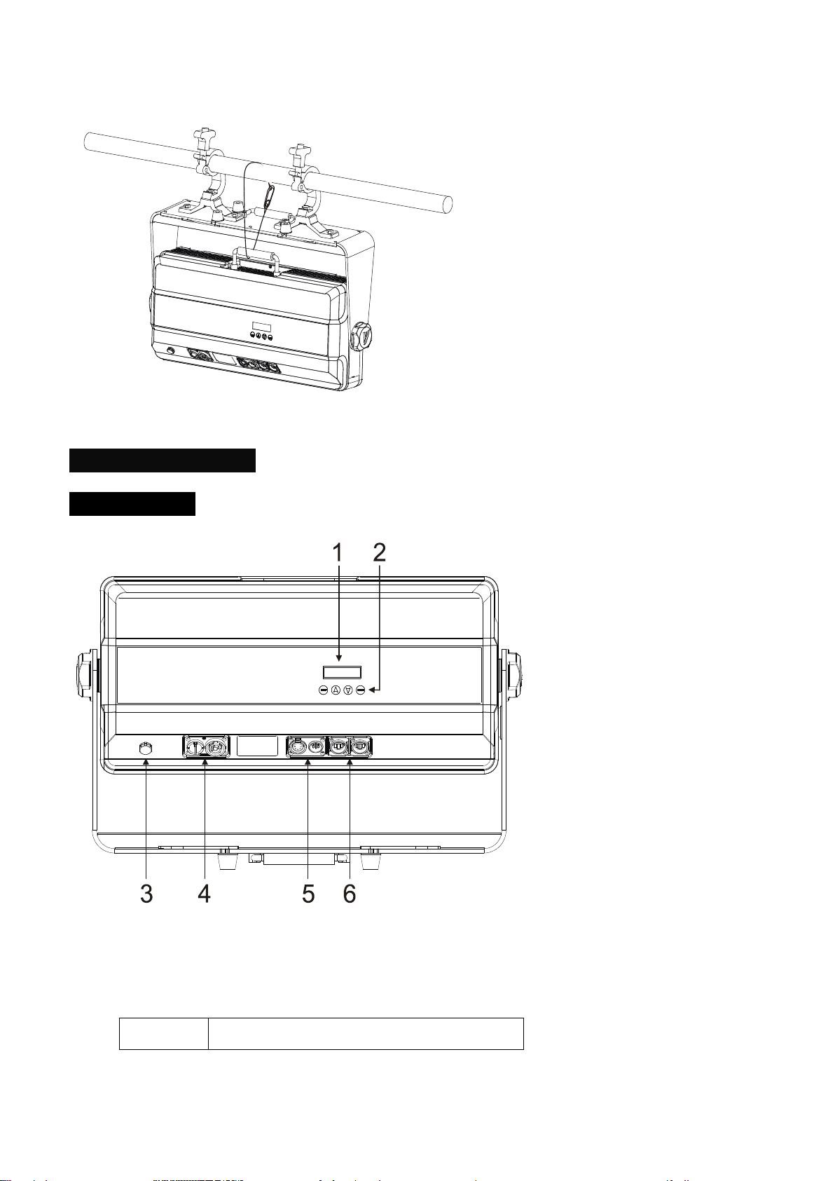
Installation:
The unit is fully operational in three different mounting positions, hanging upside-down from a
ceiling or set on a flat level surface. To avoid internal damage to the unit, never mount the unit on its
side as illustrated above. Be sure this fixture is kept at least 0.5m away from any flammable materials
(decoration etc.). Always use and install the supplied safety cable as a safety measure to prevent
accidental damage and/or injury in the event the clamp fails.
Please read the instruction carefully which includes important
information about the installation, usage and maintenance.

3B
1. Bolt each clamp to the Omega holder with screw and lock nut through the hole in the holder.
2. Faster the omega holders on the bottom of the base by inserting quick-lock fasteners into the
holes of the base and tighten fully clockwise.
3. Hang the fixture to the support through clamp and faster the screws, Faster the safety cable
through the bottom of the base and over the support.
2. Technical Specifications
13 channel Modes;
Ideal for discotheques, clubs, bars, parties, Mobile DJs, etc.
Input Voltage: AC100V~240V,50/60Hz
Total Power consumption:1500W
Power Cord Daisy Chain: 1Fixtuer(120V); 2 Fixtuer(220V);
Beam Angle:110°
IP Grade: IP 65
LED Sources: 0.4W RGBW x 2304
Dimension: 623x123x387mm
Weight: 16 Kgs

4B
3. Installation and Connection
The unit should be mounted via its screw holes on the bracket. Always ensure that the unit is firmly fixed
to avoid vibration and slipping while operating. Always ensure that the structure to which you are
attaching the unit is secure and is able to support a weight of 10 times of the unit’s weight. Also always
use a safety cable that can hold 12 times of the weight of the unit when installing the fixture.
The equipment must be fixed by professionals. And it must be fixed at a place where is out of the touch
of people and has no one pass by or under it. The unit should be mounted in the height of 0 to 30m.
Method for using lamp hook and safety rope

5B
4. How to set the unit
4.1 Rear Panel
○
1Display: Show the various menus and the selected functions;
○
2Button:
MENU
To select the programming functions

6B
DOWN
To go forward in the selected functions
UP
To go backward in the selected functions
ENTER
To confirm the selected functions
○
3Breathable punishment
○
4Power input/output
For DMX512 link, use 3/5-pin XLR plug cable to input DMX signal, and to link the next unit.
○
5DMX input/output:
For DMX512 link, use 3/5-pin XLR plug cable to input DMX signal, and to link the next unit.
○
6Ethernet in/ Ethernet Thru:For ArtNet link
4.2 Main Function
To select any functions, press MENU button until the required one is shown on the display. Select the
function by ENTER button. Use DOWN and UP button to change the mode. Once the required mode has
been selected, press ENTER button to setup or it will return to the main functions without any change
after idling 8 seconds automatically. Back to the functions without any change press MENU button. The
main functions are shown below:

7B

8B
DMX Setting
Select the DMX Setting, press the ENTER button and the display will blink. Use the DOWN and UP
button to change the DMX 512 address(001-512)or Elthernet Setup,In Elthernet Setup menu,fixture
Elthernet parameter ,IP Address/Subnet Mask/Net(0-127)/Subnet(0-15)/Universe(0-15) ,Must be
consistent with the value of the controller,Fixture receives the corresponding ArtNet signal control.
Once the address has been selected, press the ENTER button to setup or exit menu mode without any
change after 8 seconds automatically. Back to the previous functions without any change press the
MENU button.
Channel Mode
Select the Channel Mode, press the ENTER button. Use the DOWN and UP button to select the Channel,
there are 13 channel Modes. Once selected, press the ENTER button to store. Press the MENU button
back to the last menu without any change or idling 1 minute to exit menu mode.
DMX Last State
Select the DMX Last State, press the ENTER button. Use the DOWN and UP button to select Blackout or
Hold . Once selected, press the ENTER button to store. Press the MENU button back to the last menu
without any change or idling 8 seconds to exit menu mode.
Dimmer curve
Select the Dimmer curve, press the ENTER button. Use the DOWN and UP button to select the curve you
need. Once selected, press the ENTER button to setup or exit menu mode without any change after 8
seconds. Back to the functions without any change press the MENU button again.
Dimmer mode 1 Dimmer mode 2 Dimmer mode 3 Dimmer mode 4

9B
Optically Linear Square Law Inverse-Square Law S-Curve
Mode 1(Optically Linear): The increase in light intensity appears to be linear as DMX value is increased.
Mode 2(Square Law): Light intensity control is finer at low levels and coarser at high levels.
Mode 3(Inverse Square Law): Light intensity control is coarser at low levels and finger at high levels.
Mode 4(S-cure): Light intensity control is finger at low levels and high levels and coarser at medium
levels.
Dimmer Speed
Select the Dimmer Speed, press the ENTER button. Use the DOWN and UP button to select Fast or
Smooth. Once selected, press the ENTER button to setup or exit menu mode without any change after 8
seconds. Back to the functions without any change press the MENU button again.
White Balance
Select the White Balance, press the ENTER button to confirm. It can be adjusted with the whole fixture,
or it can be adjusted independently for each block.Use the UP and DOWN button to select
Red/Green/Blu/White,press the ENTER button to store, then use the UP and DOWN button to adjust
the value from (125~255), press the ENTER button to confirm. (DMX signal will be the first priority under
Manual Mode.) Once selected, press the ENTER button to store. Press the MENU button back to the last
menu without any change or idling 8 seconds to exit menu mode.
Language
Select the Language, press the ENTER button to confirm. Use the UP and DOWN button to adjust
English or Chinese .Once selected, press the ENTER button to store. Press the MENU button back to the
last menu without any change or idling 8 seconds to exit menu mode.

10B
Manual Test
Select the Manual Mode, press the ENTER button to confirm. Use the UP and DOWN button to adjust
the value for Red,Green,Blue,White, Intensity, Durate or Rate from 0~255, press the ENTER button to
confirm. (DMX signal will be the first priority under Manual Mode.) Once selected, press the ENTER
button to store. Press the MENU button back to the last menu without any change or idling 8 seconds to
exit menu mode.
Auto Test
Select Auto Test, press the ENTER button to confirm. The unit will test by itself automatic. Press the
MENU button back to the last menu or idling 8 seconds to exit menu mode.
Temperature
Select Temp., press the ENTER button to confirm. Display will show the temperature of the fixture. Press
the MENU button back to the last menu or idling 8 seconds to exit menu mode.
Fixture Hours
Select Fixture Hours, press the ENTER button to confirm. Display will show the number of working
hours of the unit. Press the MENU button back to the last menu or idling 8 seconds to exit menu mode.
Software Version
Select Software Version , press the ENTER button to confirm. The display will show the version of
software of the unit. Press the MENU button back to the last menu or idling 8 seconds to exit menu mode.
Factory Reset
Select Factory Reset, press the ENTER button to confirm. Use the UP and DOWN button to adjust the
NO/Yes.Select Yes, fixture will resume factory settings. Press the MENU button back to the last menu or
idling 8 seconds to exit menu mode.

11B
Fault report : 1、Fan.Error 2、Temp.Errot
RDM function table
DMX START
0-512
MANUFAC TURER
ACME
DEVICE MODEL DESCRIPTION
THUNDERSTRUCK
DMX PERSONALITY DMX 4/4Channel( 8 bit)
DMX 8/8Channel (16 bit)
DMX 8/8 Channel
DMX 52/52 Channel
DMX12/1 Piexl
DMX16/2V Piexl
DMX16/2H Piexl
DMX20/3 Piexl
DMX24/4 Piexl
DMX32/6V Piexl
DMX32/6H Piexl
DMX56/12 Piexl
DEVICE LABEL
THUNDERSTRUCK
IDENTIFY DEVICE
Off/On
DEVICE HOURS
SOFTWARE
RESET DEVICE
Warm/Cold

12B
5. How to control the unit
1. By DMX controller;
No need to turn the unit off when you change the DMX address, as new DMX address setting will be
affected at once. Turn on the unit, under the DMX signal , the LED will display the saved channel address
(001-512).

13B
6. DMX512 configuration
Channel Mode:

14B

15B

16B
7. DMX512 Connection
Mode connection:
1. Connect the fixture together in a “daisy chain” by XLR plug cable from the output of the fixture to
the input of the next fixture. The cable cannot be branched or split to a “Y” cable. Inadequate or
damaged cables, soldered joints or corroded connectors can easily distort the signal and shut down
the system
2. The DMX output and input connectors are pass-through to maintain the DMX circuit when one of
the units’ power is disconnected.
3. At last fixture, the DMX cable has to be terminated with a terminator to reduce signal errors. Solder
a 120-ohm 1/4W resistor between pin 2(DMX-) and pin 3(DMX+) into a 3-pin XLR-plug and plug it in
the DMX-output of the last fixture.
4. Each lighting fixture needs to have an address set to receive the data sent by the controller. The
address number is between 0-511 (usually 0 & 1 are equal to 1).
5. 3/5 pin XLR connectors:.
3 pin XLR: Pin 1: GND, Pin 2: Negative signal (-), Pin 3: Positive signal (+)
8.Troubleshooting
Following are a few common problems that may occur during operation. Here are some suggestions for
easy troubleshooting:
A. The fixture does not work, no light
1. Check the connection of power and main fuse.
2. Measure the mains voltage on the main connector.

17B
B. Not responding to DMX controller
1. DMX LED should be on. If not, check DMX connectors, cables to see if link properly.
2. If the DMX LED is on and no response to the channel, check the address settings and DMX polarity.
3. If you have intermittent DMX signal problems, check the pins on connectors or on PCB of the fixture
or the previous one.
4. Try to use another DMX controller.
5. Check if the DMX cables run near or run alongside to high voltage cables that may cause damage or
interference to DMX interface circuit.
9. Fixture Cleaning
The cleaning of internal must be carried out periodically to optimize light output. Cleaning frequency
depends on the environment in which the fixture operates: damp, smoky or particularly dirty
surrounding can cause greater accumulation of dirt on the fixture’s optics.
Clean with soft cloth using normal glass cleaning fluid.
Always dry the parts carefully.
Clean the external optics at least every 20 days. Clean the internal optics at least every 30/60 days.

18B

Innovation, Quality, Performance
Table of contents
Other ACME Lighting Equipment manuals

ACME
ACME BRIGHT User manual

ACME
ACME LED-WAV-10W User manual

ACME
ACME SABER Mini User manual

ACME
ACME VENOM LED-460 User manual

ACME
ACME LED-245/2 User manual

ACME
ACME TV LIGHT PANEL 2000 User manual

ACME
ACME ColorTec 250 LED-CC60 User manual

ACME
ACME Dynamic 25 Roller LED-SC25B User manual

ACME
ACME Dotline180 User manual

ACME
ACME DMX512 Dynamic Scan User manual

ACME
ACME V Inground VI-10QW User manual

ACME
ACME CRUX User manual

ACME
ACME LED-PS10 User manual

ACME
ACME Gemini User manual

ACME
ACME LED-SC25 User manual

ACME
ACME DIABOLO 500 User manual

ACME
ACME LED-PS10 User manual

ACME
ACME MP-12FC User manual

ACME
ACME BOOTES User manual

ACME
ACME GLORV FRAMING XP-5000SZF User manual