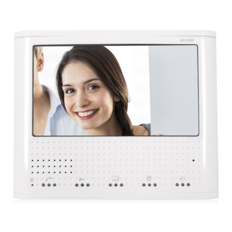
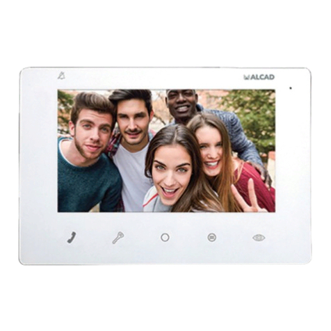
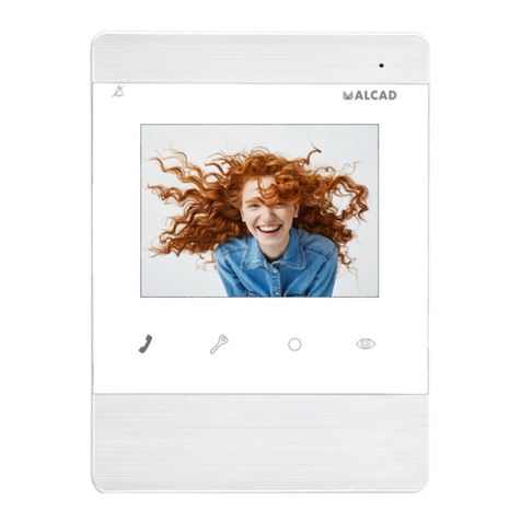
Alcad MVC-140 User manual

MONITEUR POUR VIDÉOPORTIER
MONITOR DE VIDEOPORTERO
VIDEODOOR ENTRY SYSTEM MONITOR
VIDEOPORTERO 2 HILOS
VIDÉOPORTIER 2 FILS
2-WIRE VIDEODOOR ENTRY SYSTEMS

ESP - 2 MONITOR DE VIDEOPORTERO
MONTEJE MECÁNICO
Recomendaciones
A la hora de elegir el lugar para colocar el soporte, busque una zona de la pared
plana, uniforme y dura. Tenga en cuenta las dimensiones del monitor y asegúrese de
dejar espacio suciente a la derecha del soporte (>70 mm) para poder acceder a los
controles del monitor.
Colóquelo alejado de fuentes de luz directa, evitando así efectos no deseados en
visualización de la imagen (reejos, …). Evite también fuentes intensas de calor,
humedad, vapor, que podrían limitar la vida útil del equipo.
Dimensiones del monitor y del soporte
35 mm
118 mm
21
mm
76 mm
60mm
95 mm
114 mm
169 mm

ESP - 3MONITOR DE VIDEOPORTERO
Instrucciones de instalación
x4
ON
PROG.
OFF
Ver “INSTRUCCIONES DE
CONEXIÓN”
Ver “INSTRUCCIONES DE
PROGRAMACIÓN”
Ver “INSTRUCCIONES DE
PROGRAMACIÓN”
Ver “INSTRUCCIONES DE
PROGRAMACIÓN”
1
3
2
4
x4
ON
PROG.
OFF
Ver “INSTRUCCIONES DE
CONEXIÓN”
Ver “INSTRUCCIONES DE
PROGRAMACIÓN”

ESP - 4 MONITOR DE VIDEOPORTERO
INSTRUCCIONES DE CONEXIÓN
Conexión BUS mediante derivadores
B1 B2 B2 B1
ON
MVC‐140
OFF ON
DIV‐064
B1 B2 B2 B1
ON
MVC‐140
OFF ON
TRONCAL
TRONCAL
Derivadorinterno
desactivadoentodos
losmonitores.
Cargadesactivadaen
todoslosmonitores.
OFF ON
ON
VIVIENDA1 VIVIENDA2
B1 B2 B2 B1
ON
MVC-140
OFF ON
B1 B2 B2 B1
ON
MVC-140
OFF ON
CASCADE:
Ac�va o desac�va derivador
interno
PROG:
Interruptor de programación
Ac�va o desac�va la
carga final de línea
ON
1

ESP - 5MONITOR DE VIDEOPORTERO
Recepción de llamada rellano en el monitor
Habilitar la función apertura de puerta automática al recibir llamada
B1 B2 B2 B1
ON
MVC-14 0
OFF ON
B1 B2 B2 B1
ON
MVC-14 0
OFF ON
TRONCAL
B1 B2 B2 B1
ON
MVC-14 0
OFF ON
B1 B2 B2 B1
ON
MVC-14 0
OFF ON
B1 B2 B2 B1
ON
MVC-14 0
OFF ON
B1 B2 B2 B1
ON
MVC-14 0
OFF ON Derivador interno
activado en todos los
monitores.
Carga activada sólo en
el último monitor.
Derivador interno
activado en todos los
monitores.
Carga activada sólo en
el último monitor.
OFF ON
ONON
Derivador interno
activado en todos los
monitores.
Carga activada sólo en
el último monitor.
OFF ON
ON
VI V IE N DA 1
VI V IE N DA 2
VI V IE N DA 3
MVC-14 0
B1 B2
+
S2
–
S5
–+
B2 B1
BUS
Una vez habilitada, es posible
activar y desactivar esta función
mediante una pulsación
prolongada del botón de
autoencendido. Consulte el
manual de usuario.
Una vez habilitada, es posible
activar y desactivar esta función
mediante una pulsación
prolongada del botón de
autoencendido. Consulte el
manual de usuario.
MVC-14 0
B1 B2
+
S2
–
S5
–+
B2 B1
MVC-14 0
B1 B2
+
S2
–
S5
–+
B2 B1
BUS
Pulsador de la
puerta del rellano
Pulsador de la
puerta del rellano
Al pulsar el pulsador de la
puerta del rellano el
monitor emitirá un tono
de llamada, pero no
mostrará imagen.
Al pulsar el pulsador de la
puerta del rellano el
monitor emitirá un tono
de llamada, pero no
mostrará imagen.
Conexión BUS viviendas en cascada

ESP - 6 MONITOR DE VIDEOPORTERO
VARIOS MONITORES EN LA MISMA VIVIENDA
1. Conecte todos los monitores de la vivienda.
2. Programe los monitores uno por uno y con el mismo pulsador/código,
ver “Instrucciones de programación” Página 7.
3. El monitor programado en primer lugar será el monitor principal.
Funcionamiento
Recibida la llamada en la vivienda, ésta suena en todos los monitores. La imagen del
visitante se muestra automáticamente en el primer monitor que haya programado
en dicha vivienda. Posibilidad de visualizar la imagen en el resto de monitores
sin necesidad de descolgar, presionando el botón de autoencendido . Puede
responder la llamada desde cualquiera de los monitores pulsando el botón de
comunicación. Una vez establecida la comunicación desde uno de los monitores no
será posible descolgar desde ningún otro, manteniendo en todo momento el secreto
de la comunicación.
B1 B2 B2 B1
ON
MVC‐140
OFF ON
DIV‐064
B1 B2 B2 B1
ON
MVC‐140
OFF ON
TRONCAL
TRONCAL
Derivadorinterno
desactivadoentodos
losmonitores.
Cargadesactivadaen
todoslosmonitores.
OFF ON
ON
2MONITORESENLAMISMAVIVIENDA
ASC‐050
Ctrl1
Ctrl2
S2
2
S5
5
AAL‐200
MVC‐140
B1 B2
+
S2
–
S5
–+
B2 B1
BUS
REPETIDORDELLAMADA
MVC‐140
B1 B2
+
S2
–
S5
–+
B2 B1
BUS
ACCESORIOSELECTOR
CONMUTADOR
Contactoslibres
depotencial
Repetidor de llamada o accesorio selector-conmutador (Relé) activado
al recibir llamada

ESP - 7MONITOR DE VIDEOPORTERO
INSTRUCCIONES DE PROGRAMACIÓN
La programación del monitor debe realizarse desde la placa de calle principal del
sistema (Consulte el manual de instalación correspondiente).
El pulsador/código de programación queda memorizado en el monitor. Si se sustituye
el monitor no olvide programarlo.
Para instalaciones con varios dispositivos (teléfonos o monitores) en la misma
vivienda, programe todos los dispositivos uno a uno y con el mismo pulsador/código.
Pasos de programación
1. Desplace el interruptor PROG a la posición OFF; Vuelva a poner el
interruptor en la posición ON.
2. Pulse el botón de apertura de puerta . Se activará el audio entre el
monitor y la placa principal.
3. Situado en la placa de calle principal, realice la llamada a la vivienda
donde está situado el monitor a programar. La placa emitirá un sonido
de conrmación, el monitor ha sido programado.
Nota: Una vez programado el monitor, asegúrese de que el interruptor PROG queda
en posición ON.
Nota: Tiempo máximo de 1 minuto entre los pasos 1,2 y 3. Pasado el tiempo máximo
deberá iniciar la programación desde el paso 1.
PROG.
OFF
1
PROG.
ON
2
1 2 3

ESP - 8 MONITOR DE VIDEOPORTERO
CARACTERÍSTICAS TÉCNICAS
MONITOR ENARA
REFERENCIA 9630075 MVC-140
Sistema 2 Hilos
Pantalla TFT Color 4”
Menú en pantalla Si
Comunicación Manos libres
Regulación del volumen de
llamada “No molestar”; “Bajo”; “Alto”
Pulsadores 4 pulsadores táctiles
Pulsadores para funciones
auxiliares 1
Captura de imágenes No
Bucle magnético No
Alimentación A través del BUS 2 hilos (12 … 18Vdc)
Consumo (mA) 25 mA (en reposo); 360 mA (en activo)
Temperatura de trabajo +5… +55 ºC
Conexiones Bornas enchufables
Derivador y carga integrados Si, congurable mediante micro-inte-
rruptores
Montaje De supercie
Dimensiones 120mm X 168mm X 22mm

ALCAD Electronics, S.L. FRANCE - Hendaye
Tel. 943 63 96 60 Tel. 00 34 - 943 63 96 60
Fax 943 63 92 66 CZECH REPUBLIC - Ostrovačice
Int. Tel. +34 - 943 63 96 60 Tel. +420 546 427 059
Apdo. 455 - Pol. Ind. Arreche-Ugalde, 1Tel. +90 212 295 97 00
20305 IRUN - Spain UNITED ARAB EMIRATES - Dubai
www.alcad.net Tel. +971 4 214 61 40
Las imágenes de éste documento son puramente referenciales y pueden no coincidir con el producto.
The illustrations in this document are for reference only and may not correspond to the product in every detail.
Les images dans ce document sont pour référence uniquement et peuvent ne pas correspondre au produit.
Cod. 9630075B - Rev. 01

ENG - 10 VIDEODOOR ENTRY SYSTEM MONITOR
MECHANICAL ASSEMBLY
Recommendations
When deciding where to position the connection support, choose an area of Wall
which is smooth, even and hard. Bear in mind the dimensions of the monitor, ensuring
that you leave space enough on the right-hand side of the bracket (>70mm) to be
able to Access the controls on the monitor.
Avoid places where there are sources of direct light, thereby preventing undesired
reections on the screen of the monitor. Similarly, avoid sources of strong heat, damp
or steam, which could reduce the operational life of the equipment.
Monitor and bracket size
35 mm
118 mm
21
mm
76 mm
60mm
95 mm
114 mm
169 mm

ENG - 11VIDEODOOR ENTRY SYSTEM MONITOR
Installing instructions
x4
ON
PROG.
OFF
Ver “INSTRUCCIONES DE
CONEXIÓN”
Ver “INSTRUCCIONES DE
PROGRAMACIÓN”
See: “PROGRAMMING
INTRUCTIONS”
See: “CONNECTING
INSTRUCTIONS”
1
3
2
4
x4
ON
PROG.
OFF
Ver “INSTRUCCIONES DE
CONEXIÓN”
Ver “INSTRUCCIONES DE
PROGRAMACIÓN”

ENG - 12 VIDEODOOR ENTRY SYSTEM MONITOR
CONNECTING INSTRUCTIONS
BUS connection via tap-offs
B1 B2 B2 B1
ON
MVC-140
OFF ON
DIV-064
B1 B2 B2 B1
ON
MVC-140
OFF ON
RISER
RISER
Internal tap-off
disabled on
all monitors
Load disabled
on all monitors
OFF ON
ON
APARTMENT 1APARTMENT 2
B1 B2 B2 B1
ON
MVC-140
OFF ON
B1 B2 B2 B1
ON
MVC-140
OFF ON
CASCADE:
It enables or disables the internal
tap-off
PROG:
Programming switch
It enables or disables the
line termina�on load
ON
1

ENG - 13VIDEODOOR ENTRY SYSTEM MONITOR
Reception of call landing on the monitor
Enable automatic door opening function when receiving call
B1 B2 B2 B1
ON
MVC-140
OFF ON
B1 B2 B2 B1
ON
MVC-140
OFF ON
RISER
B1 B2 B2 B1
ON
MVC-140
OFF ON
B1 B2 B2 B1
ON
MVC-140
OFF ON
B1 B2 B2 B1
ON
MVC-140
OFF ON
B1 B2 B2 B1
ON
MVC-140
OFF ON Derivador interno
ac�vado en todos los
monitores.
Carga ac�vada sólo en
el úl�mo monitor.
Derivador interno
ac�vado en todos los
monitores.
Carga ac�vada sólo en
el úl�mo monitor.
OFF ON
ONON
Internal tap-off
enabled on all
monitors
Load enabled only
on the last monitor
OFF ON
ON
APARTMENT
1
APARTMENT
2
APARTMENT
3
MVC-140
B1 B2
+
S2
–
S5
–+
B2 B1
BUS
Una vez habilitada, es posible
acvar y desacvar esta función
mediante una pulsación
prolongada del botón de
autoencendido. Consulte el
manual de usuario.
Once enabled, it is possible to
Consult the user manual.
MVC-140
B1 B2
+
S2
–
S5
–+
B2 B1
MVC-140
B1 B2
+
S2
–
S5
–+
B2 B1
BUS
Landing call
push-button
Al pulsar el pulsador de la
puerta del rellano el
monitor emirá un tono
de llamada, pero no
mostrará imagen.
When pressing the
door the monitor will
emit a ring tone but will
not show any image.
BUS connection cascading apartments

ENG - 14 VIDEODOOR ENTRY SYSTEM MONITOR
SEVERAL MONITORS IN THE SAME APARTMENT
1. Connect all monitors in the house.
2. Program the monitors one by one and with the same button / code,
see “Programming instructions” Page 15
3. The monitor programmed in the rst place will be the main monitor.
Functioning
Received the call in the apartment, it sounds on all monitors. The visitor’s image
is automatically displayed on the rst monitor that you have programmed in that
apartment. Possibility of displaying the image on the other monitors without having
to pick up the receiver, by pressing the auto-switch on button . You can answer
the call from any of the monitors by pressing the communication button. Once the
communication is established from one of the monitors, it will not be possible to pick
up from any other, keeping the secret of the communication at all times.
B1 B2 B2 B1
ON
MVC-140
OFF ON
DIV-064
B1 B2 B2 B1
ON
MVC-140
OFF ON
RISER
RISER
Internal tap-off
disabled on
all monitors
Load disabled
on all monitors
OFF ON
ON
2 MONITORS IN THE SAME APARTMENT
ASC-050
Ctrl1
Ctrl2
S2
2
S5
5
AAL-200
MVC-140
B1 B2
+
S2
–
S5
–+
B2 B1
BUS
CALL EXTENSION
MVC-140
B1 B2
+
S2
–
S5
–+
B2 B1
BUS
SWITCH SELECTOR
ACCESSORY
Poten�al free
contacts
Call repeater or selector-switch accessory (Relay) activated when
receiving call

ENG - 15VIDEODOOR ENTRY SYSTEM MONITOR
PROGRAMMING INSTRUCTIONS
The programming of the monitor must be done from the main entrance panel of the
system (See the corresponding installation manual).
The button / programming code is stored in the monitor. If the monitor is replaced, do
not forget to program it.
For installations with several devices (telephones or monitors) in the same home,
program all the devices one by one and with the same button / code.
Programming steps
1. Move the PROG switch to the OFF position; Return the switch to the
ON position.
2. Press the door open button . The audio will be activated between
the monitor and the main entrance panel.
3. Located on the main street panel, make the call to the apartment
where the monitor to be programmed is located. The entrance panel
will emit a conrmation beep, the monitor has been programmed.
Note: Once the monitor is programmed, make sure that the PROG switch is in the
ON position.
Note: Maximum time of 1 minute between steps 1,2 and 3. After the maximum time
you must start programming from step 1.
PROG.
OFF
1
PROG.
ON
2
1 2 3

ENG - 16 VIDEODOOR ENTRY SYSTEM MONITOR
TECHNICAL CHARACTERISTICS
MONITOR ENARA
REFERENCE 9630075 MVC-140
System 2 wires
screen TFT Colour 4”
On-screen menu Yes
Communication Free hands
call volume regulation “Do not disturb”; “Medium”; “High”
Buttons 4 touch buttons
Buttons for auxiliary functions 1
Capture images No
Magnetic loop No
Imput Voltage Through the 2-wires BUS (12 … 18Vdc)
Consumption (mA) 25 mA (rest); 360 mA (active)
Work temperature +5… +55 ºC
Connetions Pluggable terminals
Integrated load and bypass Yes, congurable by micro-switches
Installation Surface mount
Proportions 120mm X 168mm X 22mm

ALCAD Electronics, S.L. FRANCE - Hendaye
Tel. 943 63 96 60 Tel. 00 34 - 943 63 96 60
Fax 943 63 92 66 CZECH REPUBLIC - Ostrovačice
Int. Tel. +34 - 943 63 96 60 Tel. +420 546 427 059
Apdo. 455 - Pol. Ind. Arreche-Ugalde, 1Tel. +90 212 295 97 00
20305 IRUN - Spain UNITED ARAB EMIRATES - Dubai
www.alcad.net Tel. +971 4 214 61 40
Las imágenes de éste documento son puramente referenciales y pueden no coincidir con el producto.
The illustrations in this document are for reference only and may not correspond to the product in every detail.
Les images dans ce document sont pour référence uniquement et peuvent ne pas correspondre au produit.
Cod. 9630075B - Rev. 01

FRA - 18 MONITEUR POUR VIDEOPORTIER
ASSEMBLAGE MECANIQUE
Recommendations
Pour positionner le support de connexions, choisissez une surface de mur plane,
uniforme et dure. Tenez compte des dimensions du moniteur qui sera ensuite
connecté au support de connexions et assurez-vous que vous laissez sufsamment
de place du côté droit du support (> 70 mm) pour pouvoir accéder au contrôle du
volume d’appel du moniteur.
Choisissez un endroit éloigné des sources de lumière directe, évitant ainsi des
problèmes de réexion sur l’ecran. De même, évitez les sources intensives de chaleur,
d’humidité et de vapeur, qui sont susceptibles de réduire la vie du matériel.
Dimensions du moniteur et du support
35 mm
118 mm
21
mm
76 mm
60mm
95 mm
114 mm
169 mm

FRA - 19MONITEUR POUR VIDEOPORTIER
Consignes d’installation
x4
ON
PROG.
OFF
Ver “INSTRUCCIONES DE
CONEXIÓN”
Ver “INSTRUCCIONES DE
PROGRAMACIÓN”
Voir instructions de
programmation
Voir instructions de
connection
1
3
2
4
x4
ON
PROG.
OFF
Ver “INSTRUCCIONES DE
CONEXIÓN”
Ver “INSTRUCCIONES DE
PROGRAMACIÓN”

FRA - 20 MONITEUR POUR VIDEOPORTIER
CONSIGNE DE BRANCHEMENT
Connexion de bus par des déviateurs
B1 B2 B2 B1
ON
MVC-140
OFF ON
DIV-064
B1 B2 B2 B1
ON
MVC-140
OFF ON
TRONC
TRONC
Dérivateur interne
désac�vé sur tout
les moniteurs
Charge désac�vée sur
tout les moniteurs
OFF ON
ON
LOGEMENT
1
LOGEMENT
2
B1 B2 B2 B1
ON
MVC-140
OFF ON
B1 B2 B2 B1
ON
MVC-140
OFF ON
CASCADE:
Ac�ve ou désac�ve le dérivateur
interne
PROG:
Intérrupteur de programma�on
Ac�ve ou désac�ve
la charge de fin de ligne
ON
1
Other manuals for MVC-140
1
This manual suits for next models
1
Table of contents
Languages:
Other Alcad Intercom System manuals

Alcad
Alcad RPS-011 User manual

Alcad
Alcad 201 Series User manual

Alcad
Alcad MVC-151 User manual

Alcad
Alcad 972 Series User manual

Alcad
Alcad GRF-200 User manual

Alcad
Alcad 963 Series User manual

Alcad
Alcad 967 Series User manual

Alcad
Alcad 967 Series User manual

Alcad
Alcad 980 Series User manual

Alcad
Alcad TCB-010 User manual

Alcad
Alcad AAL-200 User manual

Alcad
Alcad GRF-201 User manual
Alcad
Alcad TED-001 User manual

Alcad
Alcad MVB-003 User manual

Alcad
Alcad GRF-302 User manual

Alcad
Alcad 980 Series User manual

Alcad
Alcad GRF-200 User manual

Alcad
Alcad TCB-010 User manual
Alcad
Alcad MVC-141 User manual

Alcad
Alcad GRF-400 User manual