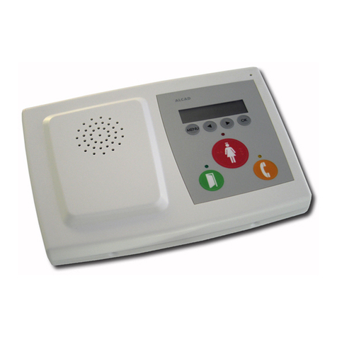
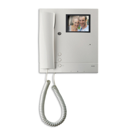
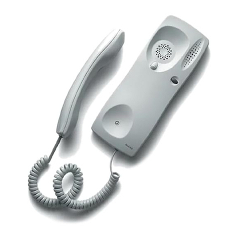
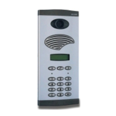
Alcad GRF-304 User manual

GRF-304 RVE-014
ÍNDICE
PLACAS DE CALLD: MÓDULO SUPERIOR CON GRUPO FÓNICO
ELEMENTOS Y DIMENSIONES ....................................................................................................................................2
SISTEMA 2 HILOS CON PULSADORES
DESCRIPCIÓN ............................................................................................................................................................3
FUNCIONAMIENTO ...................................................................................................................................................3
GENERALIDADES DE INSTALACIÓN: CABLEADO ........................................................................................................6
URBANI ACIÓN, 3 EDIFICIOS DE 8 VIVIENDAS. 1 ACCESO EXTERIOR (CANCELA)......................................................9
CONEXIÓN DEL GRUPO FÓNICO CON LA PLACA CON PULSADORES .....................................................................13
AMPLIACIÓN DE INSTALACIONES............................................................................................................................14
INSTRUCCIONES DE INSTALACIÓN Y AJUSTE...........................................................................................................15
INSTRUCCIONES DE CONFIGURACIÓN DE PLACA DE CALLE....................................................................................18
PLACA DE CALLE EXTERIOR: ASIGNACIÓN DE PULSADORES A CADA EDIFICIO ........................................................19
CARACTERÍSTICAS TÉCNICAS...................................................................................................................................23
VERIFICACIÓN DE LA INSTALACIÓN.........................................................................................................................24
INDEX
ENTRANCE PANELS: UPPER MODULE WITH AUDIO UNIT
ELEMENTS AND DIMENSIONS....................................................................................................................................2
2-WIRE SYSTEM WITH PUSHBUTTONS
DESCRIPTION.............................................................................................................................................................3
OPERATION ...............................................................................................................................................................4
OVERVIEW OF THE INSTALLATION: WIRING...............................................................................................................6
COMPOUND, 3 BUILDINGS OF 8 DWELLINGS EACH. 1 EXTERNAL POINT OF ENTRY (GATEHOUSE)............................9
HOW TO CONNECT THE AUDIO UNIT TO THE PUSHBUTTON PANEL ........................................................................13
EXTENDING INSTALLATIONS ....................................................................................................................................14
INSTALLING AND ADJUSTMENT INSTRUCTIONS .......................................................................................................1
ENTRANCE PANEL CONFIGURATION INSTRUCTIONS...............................................................................................18
OUTER ENTRANCE PANEL: ASSIGNING PUSHBUTTONS TO EACH BUILDING.............................................................19
TECHNICAL CHARACTERISTICS.................................................................................................................................23
TROUBLE SHOOTING ...............................................................................................................................................2
SOMMAIRE
PLAQUES DE RUD: MODULES SUPÉRIEURS
ELEMENTS ET MESURES..............................................................................................................................................2
SYSTÈME À 2 FILS AVEC BOUTONS POUSSOIRS
DESCRIPTION.............................................................................................................................................................3
FONCTIONNEMENT...................................................................................................................................................4
GÉNÉRALITÉS DE L'INSTALLATION: CÂBLAGE..............................................................................................................6
ÎLOT, 3 BÂTIMENTS DE 8 LOGEMENTS CHACUN. 1 ACCÈS EXTÉRIEUR........................................................................9
BRANCHEMENT DU GROUPE PHONIQUE A LA PLAQUE AVEC BOUTONS POUSSOIRS..............................................13
EXTENSION DES INSTALLATIONS..............................................................................................................................14
INSTRUCTIONS D'INSTALLATION ET DE RÉGLAGE.....................................................................................................15
INSTRUCTIONS DE CONFIGURATION DE LA PLAQUE DE RUE ...................................................................................18
PLAQUE DENTRÉE EXTERND: ATTRIBUTION DES BOUTONS-POUSSOIRS À CHAQUE BÂTIMENT................................19
CARACTÉRISTIQUES TECHNIQUES............................................................................................................................23
PROBLÉMES DE FONCTIONNEMENT ........................................................................................................................26
VIDEOPORTERO 2 HILOS
2-WIRE VIDEODOOR ENTRY SYSTEM
VIDÉOPORTIER 2 FILS
PORTERO 2 HILOS
2-WIRE DOOR ENTRY SYSTEM
PORTIER 2 FILS
SISTEMA DE PORTERO-VIDEOPORTERO CON PULSADORES
DOOR-VIDEODOOR ENTRY SYSTEMS WITH PUSH-BUTTONS
SISTÈMES DE PORTIER-VIDÉOPORTIER AVEC BOUTONS POUSOIRS
VIDEOPORTERO 2 HILOS - 2-WIRE VIDEODOOR ENTRY SYSTEMS - VIDÉOPORTIER 2 FILS

ELEMENTOS Y DIMENSIONES - ELEMENTS AND DIMENSIONS - ELEMENTS ET MESURES
B
128 mm
MAN-501
M dulos interiores
Inside mod les
Modules interieurs
B: Consulte hoja de normas de la placa con pulsadores
B: See the datasheet of the pushbutton entrance panel.
B: Voir la fiche technique de la plaque de rue aux boutons poussoirs.
PLACAS DE CALLD: MÓDULO SUPERIOR CON GRUPO FÓNICO
ENTRANCE PANELS: UPPER MODULE WITH AUDIO UNIT
PLAQUES DE RUD: MODULES SUPÉRIEURS
9770035
RVE-014
MÓDULO
MODULE
MODULE
RVE-014
GRF-304
9610048
GRF-304
9670168 MAN-501
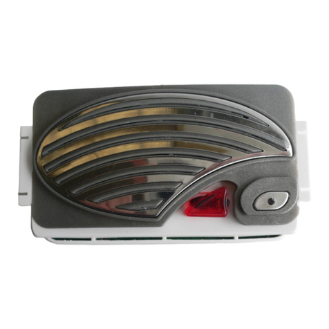
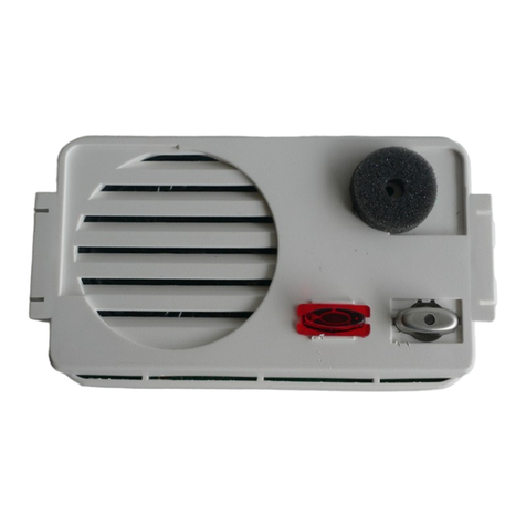
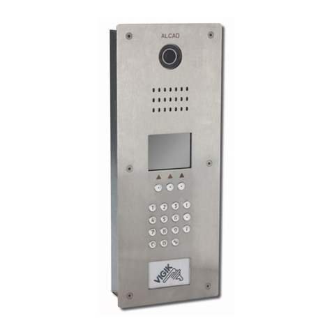
Módulo con grupo fónico para cancela, sistema 2 hilos. Incluye grupo fónico modelo GRF-304, módulo frontal de placa de calle y
módulo altavoz y micrófono, modelo RVE-014.
Audio unit module for external entrance, 2-wire system. Includes a GRF-304 audio unit, a front module of entrance panel and a RVE-
014 speaker and microphone module.
Module de groupe phonique pour plaque extérieure, système à 2 fils. Inclut groupe phonique GRF-304, module frontal de la plaque
de rue et module haut-parleur et micro RVE-014.
9770035 RVE-014
Módulo altavoz y micrófono.
Speaker and microphone module.
Module haut-parleur et micro.
9610048 GRF-304
Grupo fónico para cancela, sistema 2 hilos (no incluye módulo altavoz y micrófono).
Groupe phonique pour plaque extérieure, système à 2 fils (n´inclut pas le module haut-parleur et micro).
Audio unit for external entrance, 2-wire system (does not include speaker and microphone module).
RVM-015
9770036
RVM-015
VIDEOPORTERO 2 HILOS - 2-WIRE VIDEODOOR ENTRY SYSTEMS - VIDÉOPORTIER 2 FILS
14 mm
2

FUNCIONAMIENTO
Sistema que permite realizar instalaciones en edificios de uno o varios accesos y urbanizaciones con varios edificios interiores.
Tamaño pequeño-medio.
El sistema permite gestionar instalaciones en:
- Edificios de hasta 96 viviendas (monitores/teléfonos). Hasta 6 puntos de entrada o accesos.
- Urbanizaciones de hasta 31 edificios con placa de calle con pulsadores. Hasta 6 puntos de entrada o accesos exteriores
(cancelas) a la urbanización.
- Número máximo de viviendas totales de la urbanización, 96.
- Hasta 6 puntos de entrada o accesos por edificio.
Hasta 6 dispositivos (monitores/teléfonos) por vivienda
Conexión 2 hilos, sin polaridad de conexión, tanto entre placas como hacia los dispositivos (monitores/teléfonos) de las viviendas.
La programación de cada soporte de conexiones/teléfono de cada edificio se realiza desde la placa principal de dicho edificio.
Secreto de comunicación
Función de autoencendido con placa principal (desde teléfono) o en anillo (desde monitor).
Llamada electrónica. Tono de llamada en vivienda diferente en función de procedencia de la llamada (placa de edificio: principal,
secundaria; placa de acceso exterior a la urbanización).
DESCRIPCIÓN - DESCRIPTION - DESCRIPTION
System which makes it possible to perform installations in buildings with one or several points of entry and in compounds containing
several inner buildings. small-medium size.
The system can manage installations in:
- Buildings of up to 96 dwellings (monitors/telephones). up to 6 access or entry points.
- Compounds of up to 32 buildings with entrance panel with pushbuttons. up to 6 entry points or external access points
(gatehouses) to the compound
- Maximum number of houses in the compound: 96.
- Up to 6 access or entry points per building.
Up to 6 devices (monitors/telephones) per dwelling
2-wire connection, without connection polarity, both between panels and to the devices (monitors/telephones) in the dwellings.
All the telephones/connection brackets of each building are programmed from the main entrance panel of the building.
Confidentiality feature
Automatic switch-on feature with main panel (from telephone) or looped (from monitor).
Electronic call. call tone in dwelling varies depending on where the call is coming from (entrance panel of the building: main panel,
secondary; external entry point to the compound).
système qui permet de réaliser des installations dans les bâtiments avec un ou plusieurs points daccès et dans les îlots de maisons
qui contiennent plusieurs bâtiments de petite à moyenne taille.
le système permet de gérer des installations dans:
- Des bâtiments contenant jusquà 96 logements (moniteurs/téléphones). jusquà 6 points dentrée ou daccès.
- Îlots de maisons contenant jusquà 32 bâtiments avec plaque dentrée avec boutons-poussoirs. jusquà 6 points dentrée ou
daccès externes à lîlot.
- Nombre maximum de logements dans lîlot : 96.
-Jusquà 6 points dentrée ou daccès par bâtiment.
Jusquà 6 appareils (moniteurs/téléphones) par logement
Connexion à 2 fils, sans polarité de connexion, aussi bien entre les plaques quaux appareils (moniteurs/téléphones) qui sont dans
les logements.
Tous les téléphones/supports de connexion de chaque bâtiment sont programmés depuis la plaque dentrée principale du bâtiment.
Secret de conversation
Fonction dauto-allumage avec la plaque principale (depuis le téléphone) ou en boucle (depuis le moniteur).
appel électronique. la tonalité dappel dans le logement varie selon la provenance de lappel (plaque dentrée du bâtiment : plaque
principale, plaque secondaire; point daccès externe à lîlot).
SISTEMA 2 HILOS CON PULSADORES
2-WIRE SYSTEM WITH PUSHBUTTONS
SYSTÈME À 2 FILS AVEC BOUTONS POUSSOIRS
VIDEOPORTERO 2 HILOS - 2-WIRE VIDEODOOR ENTRY SYSTEMS - VIDÉOPORTIER 2 FILS
Dos estados de funcionamiento: sistema en reposo y sistema activo.
SISTEMA EN REPOSO
Los teléfonos/monitores se encuentran por defecto inactivos, de manera que las funciones de comunicación con la placa de calle y
apertura de puerta están inhabilitadas. Las placas de calle se encuentran en reposo, con el sistema de audio deshabilitado y a la
espera de que se realice alguna llamada o de que algún teléfono active el sistema de autoencendido.
SISTEMA ACTIVO
El sistema pasa de estado de reposo a activo cuando el teléfono/monitor de una vivienda recibe llamada desde una placa de calle o
cuando se activa la función de autoencendido desde uno de los teléfonos/monitores.
Funci n de autoencendido
Descolgando el auricular y pulsando el botón de autoencendido del teléfono/monitor, podrá establecer comunicación con la placa
de calle principal del edificio, permitiéndole asimismo la apertura de la puerta. Tiempo de autoencendido: 60 segundos, hasta colgar
el auricular o se realice una llamada desde placa de calle.
En caso de monitor, visualizará asimismo la imagen captada por la telecámara. La pulsación repetida del botón de autoencendido
activará dicha función en cada una de las placas de calle de la instalación. Consulte Función de autoencendido en anillo.
3
OPERATION
FONCTIONNEMENT
VIDEOPORTERO 2 HILOS - 2-WIRE VIDEODOOR ENTRY SYSTEMS - VIDÉOPORTIER 2 FILS
There are two operating states: system on standby and system active.
SYSTEM ON STANDBY
By default the telephones/monitors are inactive, so that the functions of communicating with the entrance panel and opening the door
are disabled. The entrance panels are on standby, with the audio system disabled while waiting for a call to be made or for a telephone
to activate the automatic switch-on system.
SYSTEM ACTIVE
The system changes from being on standby to being in the active state when the telephone/monitor in a dwelling receives a call from
an entrance panel or when the automatic switch-on feature is activated from one of the telephones/monitors.
A tomatic switch-on feat re
By picking up the receiver and pressing the automatic switch-on button of the telephone/monitor, you will be able to establish
communication with the main entrance panel of the building as well as to open the street door. Duration of automatic switch-on: 60
seconds, or until the receiver is put down or a call is made from the entrance panel.
If you have a monitor, you will also be able to see the image captured by the camera. Repeatedly pressing the automatic switch-on
button will activate this feature in each of the entrance panels of the installation. See The Looped automatic switch-on function.
Receiving a call
Only telephones/monitors associated to the pushbutton will receive the call. The call is confirmed at the entrance panel. If the receiver
of another telephone/monitor is picked up, beeping tones will be heard. If the receiver of the telephone/monitor is off the hook or if
no telephone/monitor is associated to that pushbutton, the panel will emit beeping tones. Time allowed to answer: 30 seconds. Maximum
conversation time: 60 seconds. Prolongation of conversation time: +60 seconds.
The panels of the other blocks will remain on standby until a call has been made. If the call is made from the external point of entry,
the entrance panel of the building where the telephone/monitor is located will be deactivated (blocked). The red light on this entrance
panel will blink during the answering and conversation periods, thereby informing any visitor that another panel is active.
4
Il y a deux états de fonctionnement : système en veille et système actif.
SYSTÈME EN VEILLE
Par défaut, les téléphones/moniteurs sont inactifs, de sorte que les fonctions de communication avec la plaque dentrée et douverture
de porte soient inhibées. Les plaques dentrée sont en veille, avec le système audio inhibé en attendant que quelquun fasse un appel
ou quun téléphone active le système dautoallumage.
SYSTÈME ACTIF
Le système passe de létat de veille à létat actif lorsque le téléphone/moniteur dun logement reçoit un appel depuis une plaque dentrée
ou lorsque la fonction dautoallumage est activée depuis un des téléphones/moniteurs.
Fonction dautoallumage
En décrochant le combiné et en appuyant sur le bouton dauto-allumage du téléphone/du moniteur, vous pourrez établir la communication
avec la plaque dentrée principale de limmeuble ; de même vous pourrez ouvrir la porte de la rue. Durée dauto-allumage: 60 secondes,
ou jusquà ce quon raccroche le combiné ou quon passe un appel depuis la plaque dentrée.
Si vous avez un moniteur, vous pourrez également voir limage captée par la caméra. Appuyer à plusieurs reprises sur le bouton
dauto-allumage activera cette fonction dans chacune des plaques dentrée de linstallation. Voir "fonction dauto-allumage en boucle".
Réception dun appel
Seuls les téléphones/moniteurs associés à un bouton-poussoir recevront lappel. Confirmation de lappel sur la plaque dentrée. Si le
combiné dun autre téléphone/moniteur est décroché, on entendra des tonalités intermittentes. Si le combiné du téléphone/moniteur
est déjà décroché, ou si aucun téléphone/moniteur nest associé à ce bouton-poussoir, la plaque émettra des tonalités intermittentes.
Temps pour répondre : 30 secondes. Temps de conversation maximum : 60 secondes. Prolongation du temps de conversation: + 60
secondes.
Les plaques des autres blocs seront au repos, dans lattente dun nouvel appel. Si lappel est réalisé de laccès extérieur, la plaque de
rue où se trouve le téléphone/moniteur est inhibée. La lumière rouge de cette plaque clignotera pendant les temps de réponse et de
conversation, signalant ainsi au visiteur quune autre plaque est activée.
Recepci n de la llamada
Sólo los teléfonos/monitores asociados al pulsador recibirán la llamada. Confirmación de llamada en placa. Si se levanta el auricular
de otro teléfono/monitor del mismo edificio, oirá tonos intermitentes. Si el auricular del teléfono/monitor está descolgado o no hay
teléfono/monitor asociado a ese pulsador, la placa emitirá tonos intermitentes. Tiempo para contestar: 30 segundos. Tiempo de
conversación máximo: 60 segundos. Prolongación tiempo de conversación: +60 segundos.
Las placas del resto de edificios permanecen en reposo, a la espera de que se realice una llamada. Si la llamada se realiza desde el
acceso exterior, la placa de calle del edificio donde esté el teléfono/monitor queda inhabilitada (bloqueada). La luz roja de dicha
placa parpadeará durante los tiempos de contestación y conversación, permitiendo avisar al visitante de que otra placa está activada.

FUNCIÓN DE AUTOENCENDIDO EN ANILLO. VIDEO PORTERO 2 HILOS
THE LOOPED AUTO-SWITCH-ON FUNCTION. 2-WIRE VIDEO DOOR ENTRY SYSTEM
FONCTION DAUTOALLUMAGE EN BOUCLE. VIDÉO PORTIER 2 FILS
The auto-switch-on function makes it possible to see the image on the monitor, communicate with the entrance panel and open the
door without having received a call.
In installations with several points of entry this function can be activated sequentially in the different entrance panels of the installation
(looped auto-switch-on), by repeatedly pressing the auto-switch-on button. Thus (See picture below), when the auto-switch-on button
is first pressed, the main entrance panel will be activated (P); then, as the button is pressed again and again, each of the secondary
entrance panels of the building will be activated in turn (S1,S2,S3,S4,S ), until eventually the loop is completed and the main entrance
panel is activated once again. In compounds, and before returning to the main panel, the external panel defined as the main panel
(EP) will be activated, followed by each of the external panels defined as secondary (ES1, ES2, ES3, ES4, ES ).
Le système dautoallumage permet dactiver sur lécran les fonctions de visualisation de limage, de communication avec la plaque
de rue et douverture de gâche, sans avoir reçu dappel.
Dans des installations avec plusieurs accès cette fonction peut être activée de manière séquentielle dans les différentes plaques de
rue de linstallation (autoallumage en boucle), en appuyant de manière séquentielle sur le bouton dautoallumage.
Dans ce cas, (Voir l'image ci-dessous) en appuyant sur le bouton dautoallumage la plaque de rue principale (P) sactivera en premier
et si le bouton reste appuyé, chacune des plaques de rue secondaire du bâtiment ensuite (S1,S2,S3,S4,S5), à la fin la plaque principale
sactivera de nouveau. Dans les îlots de maisons, et avant de retourner à la plaque principale, la plaque externe définie comme plaque
principale (EP) sera activée, et ensuite chacune des plaques externes sera définie comme secondaire (ES1, ES2, ES3, ES4, ES5).
El sistema de autoencendido permite activar en el monitor las funciones de visualización de imagen, comunicación con la placa de
calle y apertura de puerta, sin haber recibido llamada.
En instalaciones con varios accesos puede activar dicha función de manera secuencial en las diferentes placas de calle de la instalación
(autoencendido en anillo), pulsando de manera secuencial el botón de autoencendido.
En este caso (Vea dibujo inferior), al pulsar el botón de autoencendido primero se activará la placa principal (P) y posteriormente, y
a medida que vaya pulsando dicho botón, cada una de las placas de calle secundarias del edificio (S1,S2,S3,S4,S5); volviendo
finalmente a activar la placa principal. En urbanizaciones, y antes de volver a la placa principal, se activará la placa exterior definida
como principal (EP) y posteriormente, cada una de las placas exteriores definidas como secundarias (ES1, ES2, ES3, ES4, ES5).
VIDEOPORTERO 2 HILOS - 2-WIRE VIDEODOOR ENTRY SYSTEMS - VIDÉOPORTIER 2 FILS
5
P
S1
S2
S3
S4
S5
EP
ES1
ES2
ES4
ES5
ES3

230 V B1 B2 B2 B3
DIV-054
cod.9730070
B1B2 B1B2 B1B2 B1B2 B1 B2 B1B2
DIV-054
cod.9730070
B1B2 B1B2 B1B2 B1B2 B1 B2 B1B2
230 V B1 B2 B2 B3
B2 B1
END
PORTERO. URBANIZACION DE 1 A 4 EDIFICIOS - DOOR ENTRY SYSTEM. COMPOUND OF 1 TO 4 BUILDINGS
PORTIER. ÎLOT DE 1 À 4 BÂTIMENTS
GENERALIDADES DE INSTALACIÓN: CABLEADO - OVERVIEW OF THE INSTALLATION: WIRING
GÉNÉRALITÉS DE LINSTALLATION : CÂBLAGE
EDIFICIO
BUILDING
BÂTIMENT
ACCESO EXTERIOR
EXTERNAL POINT OF ENTRY
ACCÉS EXTÉRIEUR
VIDEOPORTERO 2 HILOS - 2-WIRE VIDEODOOR ENTRY SYSTEMS - VIDÉOPORTIER 2 FILS
6
Para distancias, número de edificios, equipos o tipos de cables diferentes a los indicados en las tablas pueden ser necesarios elementos
adicionales (regeneradores de tensión de BUS, amplificadores de señal,). Consulte al fabricante.
For distances, number of buildings, devices, or types of cable different from those shown in the tables, additional elements may be
necessary (e.g. BUS voltage regenerators, signal amplifiers, etc.). Consult the manufacturer.
En ce qui concerne les distances, le nombre de bâtiments, dappareils, ou les types de câble différents de ceux indiqués dans les
tableaux, des éléments complémentaires peuvent être nécessaires (régénérateurs de tension de BUS, amplificateurs du signal, etc.).
Veuillez consulter le fabricant.
ADistancia entre placa y teléfono más alejado
Distance between panel and telephone farthest away
Distance entre la plaque et le téléphone le plus éloigné
B
C
Distancia entre placa e interface alimentador
Distance between panel and power supply interface
Distance entre la plaque et linterface dalimentation
D
Distancia entre interface alimentador y teléfono más alejado
Distance between power supply interface
and telephone farthest away
Distance entre linterface dalimentation
et le téléphone le plus éloigné
LEYENDA - KEY - LEGENDE
Distancia entre placa y abrepuertas
Distance between panel and electric lock
Distance entre plaque dentrée et gâche
Tipo de cable, número de teléfonos en edificio y distancias máximas
Type of cable, total of telephones in the b ilding and maxim m distances
Type de câble, nombre de téléphones dans le bâtiment et distances maximales
TIPO DE CABLE - CABLE TYPE - TYPE DE CABLE
8
16
24
32
40
48
TELÉFONOS
TELEPHONES
TÉLÉPHONES
CAB-032
0.25mm2
AWG: 22
CAB-004
0.5mm2
AWG: 20
CAT-001
UTP
CAT 5E
CAB-007
1 mm2
AWG: 17
A: 120m
B: 30m
C: 120m
A: 110m
B: 30m
C: 110m
A: 100m
B: 30m
C: 100m
A: 85m
B: 30m
C: 70m
A: 75m
B: 30m
C: 50m
A: 65m
B: 30m
C: 50m
A: 120m
B: 65m
C: 120m
A: 110m
B: 65m
C: 110m
A: 100m
B: 65m
C: 100m
A: 85m
B: 65m
C: 85m
A: 75m
B: 65m
C: 75m
A: 65m
B: 65m
C: 65m
A: 120m
B: 100m
C: 120m
A: 110m
B: 100m
C: 110m
A: 100m
B: 100m
C: 100m
A: 85m
B: 85m
C: 85m
A: 75m
B: 75m
C: 75m
A: 65m
B: 65m
C: 65m
A: 220m
B: 20m
C: 220m
A: 200m
B: 20m
C: 130m
A: 180m
B: 20m
C: 85m
A: 160m
B: 20m
C: 60m
A: 140m
B: 20m
C: 50m
A: 120m
B: 20m
C: 40m
CAB-207
1 mm2
AWG: 17
A: 275m
B: 130m
C: 275m
A: 250m
B: 130m
C: 250m
A: 225m
B: 130m
C: 225m
A: 200m
B: 130m
C: 200m
A: 175m
B: 130m
C: 175m
A: 150m
B: 130m
C: 150m
TIPO DE CABLE - CABLE TYPE - TYPE DE CABLE
ABREPUERTAS
ELECTRIC LOCK
GÂCHE D: 20mD: 25mD: 25m
CAB-032
0.25mm2
AWG: 22
CAB-004
0.5mm2
AWG: 20
CAB-007
1 mm2
AWG: 17
D: 25m
CAB-207
1 mm2
AWG: 17
A
DIV-154
cod. 9730071
B1B2B1 B2 B1B2 B1 B2 B1B2
D
B
C
D
B

230 V B1 B2 B2 B3
DIV-054
cod.9730070
B1B2 B1B2 B1B2 B1B2 B1 B2 B1B2
DIV-054
cod.9730070
B1B2 B1B2 B1B2 B1B2 B1 B2 B1B2
230 V B1 B2 B2 B3
B2 B1
END
VIDEOPORTERO. URBANIZACIÓN DE 1 A 4 EDIFICIOS - VIDEODOOR ENTRY SYSTEM. COMPOUND OF 1 TO 4 BUILDINGS
VIDÉOPORTIER. ÎLOT DE 1 À 4 BÂTIMENTS
ACCESO EXTERIOR
EXTERNAL POINT OF ENTRY
ACCÉS EXTÉRIEUR
EDIFICIO
BUILDING
BÂTIMENT
VIDEOPORTERO 2 HILOS - 2-WIRE VIDEODOOR ENTRY SYSTEMS - VIDÉOPORTIER 2 FILS
Para distancias, número de edificios, equipos o tipos de cables diferentes a los indicados en las tablas pueden ser necesarios elementos
adicionales (regeneradores de tensión de BUS, amplificadores de señal,). Consulte al fabricante.
For distances, number of buildings, devices, or types of cable different from those shown in the tables, additional elements may be
necessary (e.g. BUS voltage regenerators, signal amplifiers, etc.). Consult the manufacturer.
En ce qui concerne les distances, le nombre de bâtiments, dappareils, ou les types de câble différents de ceux indiqués dans les
tableaux, des éléments complémentaires peuvent être nécessaires (régénérateurs de tension de BUS, amplificateurs du signal, etc.).
Veuillez consulter le fabricant.
ADistancia entre placa y monitor más alejado
Distance between panel and monitor farthest away
Distance entre la plaque et le moniteur le plus éloigné
B
C
Distancia entre placa e interface alimentador
Distance between panel and power supply interface
Distance entre la plaque et linterface dalimentation
D
Distancia entre interface alimentador y monitor más alejado
Distance between power supply interface
and monitor farthest away
Distance entre linterface dalimentation
et le moniteur le plus éloigné
LEYENDA - KEY - LEGENDE
Distancia entre placa y abrepuertas
Distance between panel and electric lock
Distance entre plaque dentrée et gâche 7
Tipo de cable, número de monitores en edificio y distancias máximas
Type of cable, n mber of monitors in the b ilding and maxim m distances
Type de câble, nombre de moniteurs
dans le bâtiment
et distances maximales
TIPO DE CABLE - CABLE TYPE - TYPE DE CABLE
ABREPUERTAS
ELECTRIC LOCK
GÂCHE D: 20mD: 25mD: 25m
CAB-032
0.25mm2
AWG: 22
CAB-004
0.5mm2
AWG: 20
CAB-007
1 mm2
AWG: 17
D: 25m
CAB-207
1 mm2
AWG: 17
TIPO DE CABLE - CABLE TYPE - TYPE DE CABLE
8
16
24
32
40
48
MONITORES
MONITORS
MONITEURS
CAB-032
0.25mm2
AWG: 22
CAB-004
0.5mm2
AWG: 20
CAT-001
UTP
CAT 5E
CAB-007
1 mm2
AWG: 17
A: 50m
B: 20m
C: 40m
A: 40m
B: 20m
C: 40m
A: 40m
B: 20m
C: 40m
A: 85m
B: 20m
C: 85m
A: 65m
B: 20m
C: 65m
A: 60m
B: 20m
C: 45m
A: 40m
B: 40m
C: 40m
A: 30m
B: 30m
C: 30m
A: 30m
B: 30m
C: 30m
A: 60m
B: 60m
C: 60m
A: 50m
B: 50m
C: 50m
A: 45m
B: 45m
C: 45m
A: 40m
B: 40m
C: 40m
A: 30m
B: 30m
C: 30m
A: 30m
B: 30m
C: 30m
A: 60m
B: 60m
C: 60m
A: 50m
B: 50m
C: 50m
A: 45m
B: 45m
C: 45m
A: 40m
B: 30m
C: 40m
A: 30m
B: 30m
C: 30m
A: 30m
B: 30m
C: 30m
A: 60m
B: 30m
C: 60m
A: 50m
B: 30m
C: 50m
A: 45m
B: 30m
C: 45m
CAB-207
1 mm2
AWG: 17
A: 125m
B: 125m
C: 125m
A: 110m
B: 110m
C: 110m
A: 100m
B: 100m
C: 100m
A: 160m
B: 130m
C: 160m
A: 150m
B: 130m
C: 150m
A: 125m
B: 125m
C: 125m
A
DIV-154
cod. 9730071
B1B2B1 B2 B1B2 B1 B2 B1B2
D
B
C
D
B

8
VIDEOPORTERO 2 HILOS - 2-WIRE VIDEODOOR ENTRY SYSTEMS - VIDÉOPORTIER 2 FILS
A EQUIPOS COLOR O B/N CON SEÑAL DE VIDEO ANALÓGICA
COLOUR OR B/W DEVICES WITH ANALOGUE VIDEO SIGNAL
ÉQUIPEMENTS COULEUR OU N/B AVEC SIGNAL DE VIDEO ANALOGUE
B EQUIPOS COLOR CON SEÑAL DE VIDEO DIGITAL
COLOUR DEVICES WITH DIGITAL VIDEO SIGNAL
ÉQUIPEMENTS COULEUR AVEC SIGNAL DE VIDEO NUMERIQUE
COMPATIBILIDAD ENTRE EQUIPOS
DEVICES COMPATIBLE WITH EACH OTHER
COMPATIBILITE ENTRE EQUIPEMENTS
MVB-003
MVB-004
MVC-007
MVC-008
SCM-051 TET-002
TET-004
COLOR
COLOUR
COULEUR
B/N
B/W
N/B
A
MVB-003MVC-007
SCM-051
TET-002
COLOR
COLOUR
COULEUR
B
MVC-003
SCM-050
TET-002
MVN-507
MVN-508
MVN-507MVN-508
MVN-506
MVC-004
MVC-014
MVN-907
MVN-908
MVN-907MVN-908
MVC-003
MVC-004
MVC-014
SCM-050 TET-002
TET-004
MVN-506
MVN-906
MVB-004
TET-004
TET-004
MVC-008
Algunos equipos del sistema 2 Hilos no son compatibles entre si. No mezcle equipos del grupo A con equipos del grupo B en la misma
instalación.
Some devices with 2-wire system are incompatible with others. Do not mix devices from group A with devices from group B in the same
installation.
Certains équipements du système à 2 fils ne sont pas compatibles entre eux. Ne mélangez pas des équipements du groupe A et des
équipements du groupe B dans la même installation.

DIV-054
cod.9730070
B1B2 B1B2 B1B2 B1B2 B1 B2 B1B2
DIV-054
cod.9730070
B1B2 B1B2 B1B2 B1B2 B1 B2 B1B2
DIV-054
cod.9730070
B1B2 B1B2 B1B2 B1B2 B1 B2 B1B2
DIV-054
cod.9730070
B1B2 B1B2 B1B2 B1B2 B1 B2 B1B2
DIV-054
cod.9730070
B1B2 B1B2 B1B2 B1B2 B1 B2 B1B2
DIV-054
cod.9730070
B1B2 B1B2 B1B2 B1B2 B1 B2 B1B2
ABR-011
(1)
ABR-011
(1) ABR-011
(1)
ESQUEMA UNIFILAR - SINGLE-WIRED DIAGRAM - SCHÉMA À UN FIL
URBANIZACIÓN 3 EDIFICIOS DE 8 VIVIENDAS. 1 ACCESO EXTERIOR (CANCELA)
COMPOUND, 3 BUILDINGS OF 8 DWELLINGS EACH. 1 EXTERNAL POINT OF ENTRY (GATEHOUSE)
ÎLOT, 3 BÂTIMENTS DE 8 LOGEMENTS CHACUN. 1 ACCÈS EXTÉRIEUR
ABR-011
(1)
MVN-506 (B)
MVN-507 (A)
MVN-508 (A)
+
MAN-500
+
PPD-52204
MVN-506 (B)
MVN-507 (A)
MVN-508 (A)
+
PPD-52104
MAN-501
+
PPD-52104
MLN-500
MTN-500
+
PPD-52104
MVN-506 (B)
MVN-507 (A)
MVN-508 (A)
+
MAN-500
+
PPD-52204
MVN-506 (B)
MVN-507 (A)
MVN-508 (A)
+
MAN-500
+
PPD-52204
MVC-007 (A)
MVC-008 (A)
MVB-003 (A)
MVB-004 (A)
MVC-003 (B)
+
SCM-051 (A)
SCM-050 (B)
TET-002
TET-004
(A), (B) Vea "Compatibilidad entre equipos" en página 8
See "Devices compatible with each other" page 8
Voir "Compatibilite entre equipements" page 8
(1) Máx. 15 Vdc, 0.5 A
VIDEOPORTERO 2 HILOS - 2-WIRE VIDEODOOR ENTRY SYSTEMS - VIDÉOPORTIER 2 FILS
2
2
2
2
DIV-054
RVE-017
B2 B1
END
DIV-051
2
DIV-154
DIV-154
cod. 9730071
B1B2B1 B2 B1B2 B1 B2 B1B2
2
2
2
2
2
DIV-054
2
2
2
2
2
ALS-020
(230
V )
230 V B1 B2 B2 B3
2
2
DIV-054
RVE-017
B2 B1
END
DIV-051
2
2
2
2
2
2
DIV-054
2
2
2
2
2
2
ALS-020
(230
V )
230 V B1 B2 B2 B3
2
2
DIV-054
RVE-017
B2 B1
END
DIV-051
2
2
2
2
2
2
DIV-054
2
2
2
2
2
ALS-020
(230
V )
230 V B1 B2 B2 B3
2
2 2
ACCESO EXTERIOR
EXTERNAL POINT OF ENTRY
ACCÉS EXTÉRIEUR
EDIFICIO 1
BUILDING 1
BÂTIMENT 1
EDIFICIO 2
BUILDING 2
BÂTIMENT 2
9
2
2
EDIFICIO 3
BUILDING 3
BÂTIMENT 3
ALS-020
(230
V )
230 V B1 B2 B2 B3
2

CONSIDERACIONES - REMARKS - OBSERVATIONS
VIDEOPORTERO 2 HILOS - 2-WIRE VIDEODOOR ENTRY SYSTEMS - VIDÉOPORTIER 2 FILS
Identificaci n de las placas de calle de los edificios
Asigne a cada edificio un número de identificación. Consulte "Instrucciones de configuración de placa de calle", página 18.
Configuraci n de las placas de calle
Configure la placa de calle del acceso exterior como placa exterior. Consulte "Instrucciones de configuración de placa de calle", página
18.
Identifique los pulsadores de la placa exterior con los edificios interiores. Consulte "Placa de calle exterior: asignación de pulsadores
a cada edificio", página 19
Programaci n de los teléfonos/soportes de conexiones de cada vivienda
El teléfono/soporte de conexiones de cada vivienda se programará desde la placa de calle principal del edificio en el que se encuentre
dicha vivienda. Consulte la hoja de normas del teléfono/soporte de conexiones.
Identifying the entrance panels of the b ildings
Assign an identification number to each building, see "Entrance panel configuration instructions", page 18.
Config ring the entrance panels
Configure the entrance panel of the external access point as an external panel, see "Entrance panel configuration instructions", page
18.
Identify the pushbuttons of the external panel with the buildings inside, see "Outer entrance panel: assigning pushbuttons to each
building" page 19.
Programming the telephones/connection brackets of each dwelling
The telephone/connections bracket of each dwelling is programmed from the main entrance panel of the building in which the dwelling
is located. See the technical datasheet of the telephone/connections bracket.
Identification des plaques dentrée des bâtiments
Assignez un numéro didentification à chaque bâtiment, voir "Instructions de configuration de la plaque de rue", page 18.
Configuration des plaques dentrée
Configurer la plaque dentrée du point daccès externe comme plaque externe, voir "Instructions de configuration de la plaque de rue",
page 18.
Identifier les boutons-poussoirs de la plaque externe avec les bâtiments intérieurs - voir "Plaque dentrée externe: attribution des boutons-
poussoirs à chaque bâtiment", page 19.
Programmation des téléphones/supports de connexion de chaque logement
Le téléphone/support de connexion de chaque logement est programmé depuis la plaque dentrée principale du bâtiment dans lequel
le logement se trouve. Voir la fiche technique du téléphone/support de connexion.
10

GRF-304
cod. 9610048
Made in Spain
GRF-304
SW1
CC1 30
39
B1 B2 B2 B3
230V~
B1B2 B2 B3
230V~
230 V
ALS-020
Placa de calle acceso exterior
External entrance panel
Plaque de rue accès extérieur
ESQUEMA DE CABLEADO DEL ACCESO EXTERIOR - WIRING DIAGRAM OF THE EXTERNAL POINT OF ENTRY - DIAGRAMME DE
CÂBLAGE DE LACCÈS EXTÉRIEUR
DIV-154
(1)
URBANIZACIÓN 3 EDIFICIOS DE 8 VIVIENDAS. 1 ACCESO EXTERIOR (CANCELA)
COMPOUND, 3 BUILDINGS OF 8 DWELLINGS EACH. 1 EXTERNAL POINT OF ENTRY (GATEHOUSE)
ÎLOT, 3 BÂTIMENTS DE 8 LOGEMENTS CHACUN. 1 ACCÈS EXTÉRIEUR
VIDEOPORTERO 2 HILOS - 2-WIRE VIDEODOOR ENTRY SYSTEMS - VIDÉOPORTIER 2 FILS
11
ABR-011
1 2 3 4 5 6 7 8
SW1
11 1812 22
B4B5
SC1SC0
12c
V
DIV-154
cod. 9730071
B1B2 B1B2 B1 B2 B1B2 B1B2
EDIFICIO 1
BUILDING 1
BÂTIMENT 1
EDIFICIO 2
BUILDING 1
BÂTIMENT 2
EDIFICIO 3
BUILDING 3
BÂTIMENT 3
Elemento de protección
Protective element
Élément de protection
(1)

GRF-302
cod. 9610044
Made in Spain
GRF-302
SW1
CC1 30
39
DIV-054
cod.9730070
B1B2 B1B2 B1 B2 B1B2 B1B2 B1 B2
DIV-054
cod.9730070
B1B2 B1B2 B1 B2 B1B2 B1B2 B1 B2
B1 B2
B1 B2
B1 B2
B1 B2
B1 B2
B1 B2 B2 B3
230V~
B1B2 B2 B3
230V~
230 V
ALS-020
DIV-054
DIV-054
RVE-017
DIV-051
ESQUEMA DE CABLEADO DE EDIFICIOS - WIRING DIAGRAM OF BUILDINGS - DIAGRAMME DE CÂBLAGE DES BÂTIMENTS
ABR-011
(1)
230 V 230 V
ABR-011
(1)
URBANIZACIÓN 3 EDIFICIOS DE 8 VIVIENDAS. 1 ACCESO EXTERIOR (CANCELA)
COMPOUND, 3 BUILDINGS OF 8 DWELLINGS EACH. 1 EXTERNAL POINT OF ENTRY (GATEHOUSE)
ÎLOT, 3 BÂTIMENTS DE 8 LOGEMENTS CHACUN. 1 ACCÈS EXTÉRIEUR
VIDEOPORTERO 2 HILOS - 2-WIRE VIDEODOOR ENTRY SYSTEMS - VIDÉOPORTIER 2 FILS
12 ABR-011
1 2 3 4 5 6 7 8
SW1
B2 B1
END
11 1812 22 B3
B2 B4 B5
SC1SC0
12c
V
2
ALS-020
230 V B1 B2 B2 B3
EDIFICIO 2
BUILDING 2
BATIMENT 2
2
EDIFICIO 3
BUILDING 3
BATIMENT 3
1 2 3 4 5 6 7 8
SW1
1 2 3 4 5 6 7 8
SW1
Número 2
Number 2
Numéro 2
Número 3
Number 3
Numéro 3
ALS-020
230 V B1 B2 B2 B3
EDIFICIO 1
BUILDING 1
BÂTIMENT 1
EDIFICIO 2
BUILDING 1
BÂTIMENT 2
EDIFICIO 3
BUILDING 3
BÂTIMENT 3
Número 1
Number 1
Numéro 1
Placa principal
Main entrance
Plaque principale
Placa principal
Main entrance
Plaque principale
Placa principal
Main entrance
Plaque principale
Edificio 2. Viviendas
Building 2. Flats
Bâtiment 2. Logements
Edificio 3. Viviendas
Building 3. Flats
Bâtiment 3. Logements
(1)
Elemento de protección
Protective element
Élément de protection
(1)

Made in Spain
30
RVE-014
cod. 9770035
Made in Spain
SW1
GRF-304
cod. 9610048
30
Made in Spain
39
12 12c
11 18 SC1 22SC0
BUS
B4 B5
V
CC1
IN
Made in Spain
IN
OU
SW1
GRF-304
cod. 9610048
30
Made in Spain
39
12 12c
11 18 SC1 22SC0
BUS
B4 B5
V
CC1
IN
CONEXIÓN DEL GRUPO FÓNICO CON LA PLACA DE PULSADORES
HOW TO CONNECT THE AUDIO UNIT TO THE PUSHBUTTON PANEL
BRANCHEMENT DU GROUPE PHONIQUE A LA PLAQUE AVEC BOUTONS POUSSOIRS
CONEXIÓN RVE-014 - HOW TO CONNECT RVE-014 - BRANCHEMENT RVE-014
CONEXIÓN RPD-011, RPS-011, RPD-012, RPS-012 - HOW TO CONNECT RPD-011, RPS-011, RPD-012, RPS-012
BRANCHEMENT RPD-011, RPS-011, RPD-012, RPS-012
Placa de calle
Entrance panel
Plaque de rue
Grupo fónico
Audio unit
Groupe phonique
Placa de calle
Entrance panel
Plaque de rue
Grupo fónico
Audio unit
Groupe phonique
CONEXIÓN DE OTROS MÓDULOS DE PLACA DE CALLE
HOW TO CONNECT OTHER ENTRANCE PANEL MODULES
BRANCHEMENT DAUTRES MODULES DE PLAQUE DE RUE
Para conectar otros módulos de placa de calle (Telecámara, tarjetero... ) consulte la hoja de normas correspondiente a dichos módulos.
To connect other entrance panel modules (video unit, card-holder, etc.), see the datasheet of the modules concerned.
Pour connecter dautres modules de plaque dentrée (caméra, porte-cartes, etc.), veuillez consulter la notice des modules concernés.
VIDEOPORTERO 2 HILOS - 2-WIRE VIDEODOOR ENTRY SYSTEMS - VIDÉOPORTIER 2 FILS
13
Iluminación continua
Permanent lighting
Éclairage en continu
Iluminación mediante el pulsador de iluminación de la placa de calle
Lighting using the light button on the entrance panel
Éclairage ponctuel en appuyant sur le bouton de lumière de la plaque de rue
Iluminación de los tarjeteros
Lighting of the cardholders
Éclairage des panneaux détiquettes
IN
SC0 22
Made in Spain
IN
OU

SW1
GRF-304
cod. 9610048
30
Made in Spain
39
12 12c
11 18 SC1 22SC0
V
CC1
IN
12 12c
11 18 SC1 22SC0
B
B3
B
V
22
0
12c 18 SC1
2
SC0
W
1
CC1
12 12c
11 18 SC1SC
12 12c
11 18 SC1S
C
BUS
B4 B5
AMPLIACIÓN DE INSTALACIONES - EXTENDING INSTALLATIONS - EXTENSION DES INSTALLATIONS
Con comunicación con la placa de calle - With communication with the entrance panel -
Avec communication avec la plaque dentrée
A
Consulte configuración del soporte conexiones del monitor.
See configuration of the connection bracket of the monitor.
Voir configuration du support de connexions du moniteur.
B
En teléfonos con pulsador auxiliar 2 - On telephones with auxiliary pushbutton 2 - Pour les téléphones avec bouton-poussoir 2
C
Abrepuertas - Electric lock - Gâche
Activaci n - Activation - Activation
Conexi n - Connection - Connexion
Abrepuertas estandar
Standard electric lock
Gâche standard
Desde la vivienda
From the dwelling
Depuis l'appartement
Pulsadores externos
External p shb ttons
Poussoirs externes
A
A
Abrepuertas inverso
Inverse electric lock
Gâche inverse
Alimentador para abrepuertas AC
Power s pply for AC electric lock
Alimentation pour la gâche CA
Alimentador
Power supply
Alimentation
12 Vac
Activaci n accesorios (modelos ASC-001, ASC-051....) mediante los pulsadores auxiliares de teléfono/monitor
Activation of accessories (models ASC-001, ASC-051, etc.) sing a xiliary p shb ttons of the telephone/monitor
Activation des accessoires (modèles ASC-001, ASC-051...) par boutons-poussoirs auxiliaires du téléphone/moniteur
Conexi n - Connection - Connexion
Accesorio
Accessory
Accessoire
Pulsador aux. 1 - A x. p shb ttons 1 - Bouton-poussoir aux. 1
Activaci n - Activation - Activation
Accesorio
Accessory
Accessoire
A
A
B
AA
C
Conexi n - Connection - Connexion Activaci n - Activation - Activation
Pulsador aux. 2 - A x. p shb ttons 2 - Bouton-poussoir aux. 2
(1) (1)
VIDEOPORTERO 2 HILOS - 2-WIRE VIDEODOOR ENTRY SYSTEMS - VIDÉOPORTIER 2 FILS
14
Abrepuertas:
Electric lock: A max.
Gâche
Elemento de protecci n: Colóquelo en las
bornas del grupo fónico donde vaya a
conectar el abrepuertas.
Protective element: Place it on the terminals
of the audio unit where you intend to connect
the electric lock.
Élément de protection: Placez-le sur les bornes
du groupe phonique à lendroit où vous
comptez connecter la gâche.
(1)

15
Retirar en el momento de
instalar la placa de calle
Remove when installing the
entrance panel
Retirer lors de l'installation
de la plaque de rue
Algunos modelos de cajas de empotrar llevan
uno o varios refuerzos para su colocación. Si es
su caso, retire dichas piezas.
Some models of flush-mounted boxes have one
or more reinforcements for fitting it to the wall. In
such cases, remove these parts.
Certains modèles de boîtiers encastrables, sont
pourvus dun ou plusieurs renforts pour être
positionnés. Dans certains cas, enlever ces pièces.
1Fije el grupo fónico a la caja de empotrar con los
tornillos suministrados.
2
Fix the audio unit to the flush-mounted box using
the screws provided.
Attachez le group phonique au boîtier encastrable
avec les vis fournies.
Realice las conexiones eléctricas. Consulte los
esquemas de cableado (Páginas 9 a 12).
3
Make the electrical connections. See the wiring
diagrams (pages 9 to 12).
Réalisez les connexions électriques. Voir les
schémas de câblage (pages 9 à 12).
Una vez realizadas las conexiones, configure la
placa de calle. Consulte "Instrucciones de
configuración de placa de calle", página 18.
4
When the connections have been made, configure
the entrance panel. See "Entrance panel
configuration instructions", page 18.
Une fois les branchements terminés, Configurez
la plaque dentrée. Voir "Instructions de
configuration de la plaque de rue", page 18.
INSTRUCCIONES DE INSTALACIÓN Y AJUSTE
INSTALLING AND ADJUSTMENT INSTRUCTIONS
INSTRUCTIONS D'INSTALLATION ET DE RÉGLAGE
VIDEOPORTERO 2 HILOS - 2-WIRE VIDEODOOR ENTRY SYSTEMS - VIDÉOPORTIER 2 FILS
Antes de sujetar las placas de calle en las bisagras de la caja de empotrar, coloque y realice las conexiones del grupo fónico. De
esta manera, realizará las conexiones con una mayor comodidad.
RECOMENDACIONES - RECOMMENDATIONS - RECOMMENDATIONS
Before fixing the entrance panel to the pins of the flush-mounted box, put the audio unit in position and make the connections. It is
much easier to make the connections in this way.
Avant de fixer la plaque dentrée aux charnières du boîtier encastrable, mettez le groupe phonique en place et faites les raccordements.
Il est beaucoup plus facile deffectuer les connexions de cette manière.

16
VIDEOPORTERO 2 HILOS - 2-WIRE VIDEODOOR ENTRY SYSTEMS - VIDÉOPORTIER 2 FILS
Sujete la placa en las bisagras de la caja de
empotrar. Consulte hoja de normas de la placa
con pulsadores.
Fix the panel onto the hinges of the flush-mounted
box. See the datasheet of the pushbutton entrance
panel.
7
Fixez la plaque sur les charnières du boîtier
encastrable. Veuillez consulter la fiche technique
de la plaque dentrée aux boutons poussoirs.
Realice las conexiones entre el grupo fónico y los
diferentes elementos de la placa (pulsadores,
módulo altavoz-micrófono, módulo telecámara,
). Consulte Conexión del grupo fónico con la
placa con pulsadores, página 13.
Make the connections between the audio unit and
the different elements of the panel (pushbuttons,
speaker-microphone module, camera module,
etc.). See How to connect the audio unit to the
pushbutton panel, page 13.
Faites les connexions entre le groupe phonique
et les différents éléments de la plaque (boutons
poussoirs, module de haut-parleur/microphone,
module de caméra, etc.). Voir "Branchement du
groupe phonique a la plaque avec boutons
poussoirs", page 13.
8
Posicione el módulo frontal en la ventana de la
placa de pulsadores, de manera que las pestañas
de dicho módulo (1) queden encajadas en las
guías laterales de la ventana (2). Presione para
fijar el módulo frontal a la placa (3).
5
Place the front module in the window of the
pushbutton panel in such a way that the tabs of
this module (1) clip into the guides on the sides
of the window (2). Press firmly to fix the front
module to the panel (3).
Positionnez le module frontal dans la fenêtre de
la plaque de boutons-poussoirs de telle manière
que les languettes du module (1) semboîtent dans
les guides latéraux de la fenêtre (2). Appuyez
pour fixer le module frontal à la plaque (3).
Posicione el módulo altavoz-micrófono y presione
para fijarlo a la placa de pulsadores.
6
Put the speaker-microphone module in position
and press firmly to fix it to the pushbutton panel.
Positionnez le module haut-parleur et micro et
appuyez pour le fixer à la plaque de boutons-
poussoirs.

17
Coloque la tapa de protección del grupo fónico.11
Place the protective cover of the audio unit in
position.
Mettez le couvercle de protection du groupe
phonique en place.
12 Fije la placa a la caja de empotrar. Consulte hoja
de normas de la placa con pulsadores.
Fix the panel to the flush-mounted box. See the
datasheet of the pushbutton entrance panel.
Fixez la plaque au boîtier encastrable. Consultez
la fiche technique de la plaque dentrée aux
boutons poussoirs.
Programe cada soporte de conexiones/teléfono
desde la placa de calle principal del edificio
(consulte la hoja de normas del soporte de
conexiones/teléfono).
El código asignado al soporte de
conexiones/teléfono dependerá del pulsador que
se asigne, correspondiendo el codigo '1' al
pulsador mas alejado respecto del grupo fónico
(pulsador derecho de la fila inferior).
9
Programme each telephone/connections bracket
from the main entrance panel of the building. (see
the technical datasheet that comes with the
connections bracket/telephone).
The code assigned to the telephone/connections
bracket will depend on the pushbutton that is
assigned; code 1 corresponds to the pushbutton
which is furthest away from the audio unit (i.e.
the right pushbutton on the bottom row).
Programmer chaque téléphone/support de
connexion de la plaque dentrée principale du
bâtiment (voir le notice qui accompagne le support
de connexion/téléphone).
Le code assigné au téléphone/support de
connexion dépendra du bouton-poussoir qui est
assigné ; le code 1 correspond au bouton-poussoir
le plus éloigné du groupe phonique (c-à-d. le
bouton-poussoir droit sur la rangée inférieure).
C digo en funci n del pulsador
Code depending on the p shb tton
Code en fonction du bouton-poussoir
Ajuste el volumen de audio en la placa de calle
(1) y en los monitores/teléfonos (2).
10
Adjust the volume level on the entrance panel (1)
and on the monitors/telephones (2).
Régler le volume du son dans la plaque de rue
(1) et dans les moniteurs/téléphones (2).
13 Asigne los pulsadores de la placa exterior a cada
uno de los edificios interiores. Consulte
"Placa de calle exterior. Asignación de pulsadores
a cada edificio", página 19
Assign the pushbuttons of the external panel to
each of the inner buildings. See "Outer entrance
panel: assigning pushbuttons to each building",
page 19
Assignez les boutons-poussoirs de la plaque
externe à chacun des bâtiments intérieurs. Voir
"Plaque dentrée externe: attribution des boutons-
poussoirs à chaque bâtiment", page 19
Acceso exterior
External point of entry
Accés extérieur
VIDEOPORTERO 2 HILOS - 2-WIRE VIDEODOOR ENTRY SYSTEMS - VIDÉOPORTIER 2 FILS
1
2
3
4
1
3
5
2
4
6
Simples
Simples
Simples
Dobles
Doubles
Doubles
Placas en paralelo
Panels in parallel
Plaques en parallèle
1
3
5
7
2
4
6
8
13
15
17
19
14
16
18
20
9
10
21
23
22
24 11
12

18
Asigne a cada edificio un número de identificación diferente, comenzando por el 1. Ejemplo: para 3 edificios, asigne los números
1, 2 y 3; para 4 edificios, 1, 2, 3 y 4 y así sucesivamente.
Assign a different identification number to each building, beginning with number 1. For example: for 3 buildings, assign the numbers
1, 2 and 3; for 4 buildings, assign the numbers 1, 2, 3 and 4; and so on.
Assignez un numéro didentification différent à chaque bâtiment, en commençant par le numéro 1. Par exemple : pour 3 bâtiments,
assignez les numéros 1, 2 et 3 ; pour 4 bâtiments, assigner les numéros 1, 2, 3 et 4 ; et ainsi de suite.
Configure la placa de calle del acceso exterior como placa exterior principal. En caso de varios accesos exteriores, asigne un número
diferente a cada una de las placas de calle exteriores del resto de accesos (placas exteriores secundarias), comenzando por el 1.
Configure the entrance panel of the external point of entry as the main external panel. Where there are several external points of entry,
assign a different number to each of the external entrance panels of the other points of entry (secondary external panels), beginning
with the number 1.
Configurez la plaque dentrée du point daccès externe comme plaque externe principale. Dans le cas de plusieurs points daccès
externes, assigner un différent numéro à chacune des plaques dentrée externes des autres points daccès (plaques externes secondaires),
en commençant par le numéro 1.
VIDEOPORTERO 2 HILOS - 2-WIRE VIDEODOOR ENTRY SYSTEMS - VIDÉOPORTIER 2 FILS
INSTRUCCIONES DE CONFIGURACIÓN DE PLACA DE CALLE
ENTRANCE PANEL CONFIGURATION INSTRUCTIONS
INSTRUCTIONS DE CONFIGURATION DE LA PLAQUE DE RUE
Número
N mber
Numéro
1
2
3
4
5
6
7
8
9
10
Número
N mber
Numéro
21
22
23
24
25
ON
12345678
ON
12345678
ACCESO EXTERIOR
EXTERIOR ENTRANCE
ACCÈS EXTÉRIEUR
11
12
13
14
15
16
EDIFICIO 1
BUILDING 1
BÂTIMENT 1
EDIFICIO 2
BUILDING 2
BÂTIMENT 2
EDIFICIO 31
BUILDING 31
BÂTIMENT 31
E S 1
E S 2
E S 3
E S 4
E S 5
PRINCIPAL
MAIN
PRINCIPALE
SECUNDARIAS
SECONDARY
SECONDARIES
E P
ON
12 345678
ON
12345678
ON
12345678
3121
17
18
19
20
26
27
28
29
30
31

PLACA DE CALLE EXTERIOR: ASIGNACIÓN DE PULSADORES A CADA EDIFICIO
OUTER ENTRANCE PANEL: ASSIGNING PUSHBUTTONS TO EACH BUILDING
PLAQUE DENTRÉE EXTERND: ATTRIBUTION DES BOUTONS-POUSSOIRS À CHAQUE BÂTIMENT
En urbanizaciones con varios edificios interiores, para poder realizar desde el acceso exterior una llamada a las diferentes viviendas,
es necesario indicarle previamente al sistema los pulsadores que corresponden a cada uno de los edificios interiores.
La asignación de pulsadores - edificio debe realizarse desde la propia placa de calle del acceso exterior.
Dicha correspondencia queda almacenada en la memoria no volátil del grupo fónico de la placa exterior. Si se sustituye el grupo
fónico de la placa exterior no olvide realizar de nuevo la asignación de pulsadores - edificio.
Para urbanizaciones con varios accesos exteriores, realice la asignación de pulsadores-edificio en cada uno de los accesos.
DESCRIPCIÓN - DESCRIPTION - DESCRIPTION
In compounds with several inner buildings, before being able to make a call from the external point of entry to the different dwellings,
it is necessary to tell the system which pushbuttons correspond to each of the inner buildings. Pushbuttons must be assigned to the
different buildings from the entrance panel of the external point of entry.
This information is stored in the non-flash memory of the audio unit of the external panel. If the audio unit of the external panel is
subsequently replaced, do not forget to re-assign pushbuttons to buildings.
For compounds with several external points of entry, pushbuttons must be assigned to buildings at each of the points of entry.
Dans les îlots de maisons avec plusieurs bâtiments intérieurs, et avant de pouvoir faire un appel à partir du point daccès externe aux
différents logements, il est nécessaire dindiquer au système les boutons-poussoirs qui correspondent à chacun des bâtiments intérieurs.
Des boutons-poussoirs doivent être assignés aux bâtiments depuis la plaque dentrée du point daccès externe.
Cette correspondance est sauvegardée dans la mémoire (non volatile) du groupe phonique de la plaque externe. Si plus tard le groupe
phonique de la plaque externe est remplacé, noubliez pas dattribuer à nouveau des boutons-poussoirs aux bâtiments.
Pour des îlots de maisons avec plusieurs points daccès externes, des boutons-poussoirs doivent être assignés aux bâtiments à chacun
des points daccès.
PASO PREVIO: ORDEN DE ASIGNACIÓN
PREVIOUS STEP: ORDER OF ASSIGNING
ÉTAPE PRÉLIMINAIRE : ORDRE DE LATTRIBUTION
Las placas de pulsadores están formadas por cajetines de una o dos filas de pulsadores. Cada cajetín está unido al siguiente por
conectores; excepto el último cajetín que se une al grupo fónico.
A la hora de ir asignando pulsadores a los diferentes edificios, deberá comenzar en la fila inferior del primer cajetín de la placa,
para finalizar en la fila superior del cajetín que se encuentra conectado al grupo fónico.
De esta manera, el pulsador derecho del primer cajetín se asignará a la primera vivienda del edificio número 1, mientras que el
pulsador izquierdo del último cajetín, se asignará a la última vivienda del último edificio de la urbanización (edificio con número más
elevado).
Vea el ejemplo siguiente.
The pushbutton panels are formed of compartments of one or two rows of pushbuttons. Each compartment is joined to the next by
connectors, except for the last compartment which is joined to the audio unit.
When assigning pushbuttons to the different buildings, it is necessary to begin with the bottom row of the first compartment of the panel
and to finish with the top row of the compartment which is connected to the audio unit.
By doing this, the right pushbutton of the first compartment will be assigned to the first dwelling of building number 1, while the left
pushbutton of the last compartment will be assigned to the last dwelling of the last building of the compound (i.e. the building with
the highest number).
An example is shown below.
SW1
GRF-302
cod. 9610044
30
Made in Spain
39
1212c
11 18 SC1 22SC0
BUS
B3
B2B 4 B5
V
CC1
IN
Acceso exterior
External point of entry
Accès extérieur
Grupo fónico
Audio unit
Groupe phonique
GRF-304
VIDEOPORTERO 2 HILOS - 2-WIRE VIDEODOOR ENTRY SYSTEMS - VIDÉOPORTIER 2 FILS
19

Les plaques de boutons-poussoirs sont formées par des compartiments dune ou deux rangées de boutons-poussoirs. Chaque compartiment
est raccordé au prochain par des connecteurs, avec lexception du dernier compartiment qui est raccordé au groupe phonique.
En assignant les boutons-poussoirs aux différents bâtiments, il est nécessaire de commencer par la rangée inférieure du premier
compartiment de la plaque et de finir avec la rangée supérieure du compartiment qui est relié au groupe phonique.
Ainsi, le bouton-poussoir droit du premier compartiment sera assigné au premier logement du bâtiment numéro 1, alors que le bouton-
poussoir gauche du dernier compartiment sera assigné au dernier logement du dernier bâtiment de lîlot (c-à-d au bâtiment avec le
numéro le plus élevé).
Regardez lexemple suivant.
EJEMPLO DE ASIGNACION: Urbanizaci n de 24 viviendas, distribuidas en 3 edificios de 8 viviendas
EXAMPLE OF ASSIGNING PUSHBUTTONS TO BUILDINGS: Compo nd of 24 dwellings, distrib ted in 3 b ildings of 8 dwellings each
EXEMPLE DATTRIBUTION: Îlot de 24 logements, distribués dans 3 bâtiments de 8 logements chacun
Asignacion pulsadores
Assigning P shb ttons
Attribution des
boutons-poussoirs
Edificio 1
Buiding 1
Bâtiment 1
Edificio 3
Buiding 3
Bâtiment 3
Viviendas
Flats
Logements
Edificio 2
Buiding 2
Bâtiment 2
Edificio 3
Buiding 3
Bâtiment 3
Viviendas
Flats
Logements
Viviendas
Flats
Logements
Viviendas
Flats
Logements
Edificio 2
Buiding 2
Bâtiment 2
Viviendas
Flats
Logements
Detalle unión cajetines pulsadores
Detail: joining of pushbutton compartments
Détail: raccordement des compartiments de bouton-poussoir
Edificio 2
Buiding 2
Bâtiment 2
Edificio 1
Buiding 1
Bâtiment 1
Asignacion pulsadores
Assigning P shb ttons
Attribution des
boutons-poussoirs
A
SW1
GRF-302
cod. 9610044
30
Made in Spain
39
1212c
11 18 SC1 22SC0
BUS
B3
B2B 4 B5
V
CC1
IN
B
SW1
GRF-302
cod. 9610044
30
Made in Spain
39
1212c11 18 SC1 22SC0
BUS
B3
B2B 4 B5
V
CC1
IN
VIDEOPORTERO 2 HILOS - 2-WIRE VIDEODOOR ENTRY SYSTEMS - VIDÉOPORTIER 2 FILS
20
PLACA CALLE EXTERIOR FORMADA POR 1 PLACA DE 24 PULSADORES
EXTERNAL ENTRANCE PANEL CONSISTING OF 1 PANEL OF 24 PUSHBUTTONS
PLAQUE DENTRÉE EXTERNE FORMÉE PAR 1 PLAQUE DE 24 BOUTONS-POUSSOIRS
PLACA CALLE EXTERIOR FORMADA POR 2 PLACAS EN PARALELO DE 12 VIVIENDAS CADA UNA
EXTERNAL ENTRANCE PANEL CONSISITING OF 2 PANELS IN PARALLEL, EACH OF THEM FOR 12 DWELLINGS
PLAQUE DENTRÉE EXTERNE FORMÉE PAR 2 PLAQUES EN PARALLÈLE DE 12 LOGEMENTS CHACUNE
1
3
5
7
2
4
6
8
1
3
5
7
2
4
6
8
1
3
5
7
2
4
6
8
1
3
2
4
1
3
5
7
2
4
6
8
5
7
6
8
1
3
5
7
2
4
6
8
Detalle unión cajetines pulsadores
Detail: joining of pushbutton compartments
Détail: raccordement des compartiments de bouton-poussoir
This manual suits for next models
1
Table of contents
Other Alcad Intercom System manuals

Alcad
Alcad GRF-204 User manual

Alcad
Alcad 4+N User manual

Alcad
Alcad 4 Plus N User manual

Alcad
Alcad ALS-020 User manual

Alcad
Alcad KVS-31121 User manual

Alcad
Alcad 980 Series User manual

Alcad
Alcad 9650006 KPD-002 User manual

Alcad
Alcad MAN-470 User manual

Alcad
Alcad 960 Series User manual

Alcad
Alcad CIC-231 User manual

Alcad
Alcad 980 Series User manual

Alcad
Alcad 201 Series User manual

Alcad
Alcad MVC-141 User manual

Alcad
Alcad TIN-022 User manual

Alcad
Alcad 980 Series User manual

Alcad
Alcad GRF-302 User manual

Alcad
Alcad GRF-200 User manual

Alcad
Alcad GRF-400 User manual

Alcad
Alcad UN-001 User manual

Alcad
Alcad CHC-041 User manual