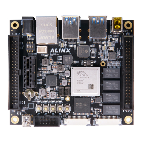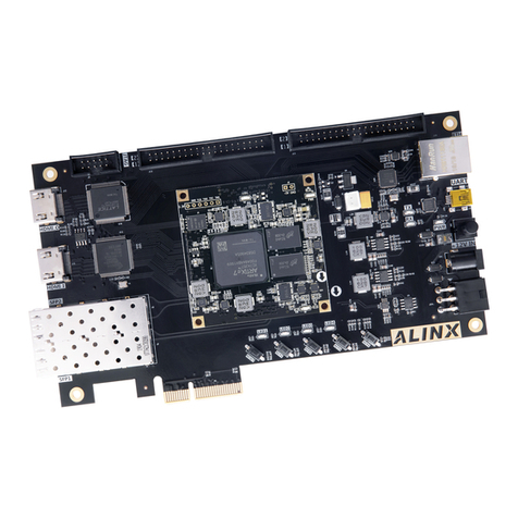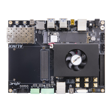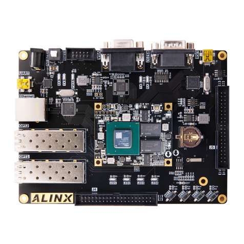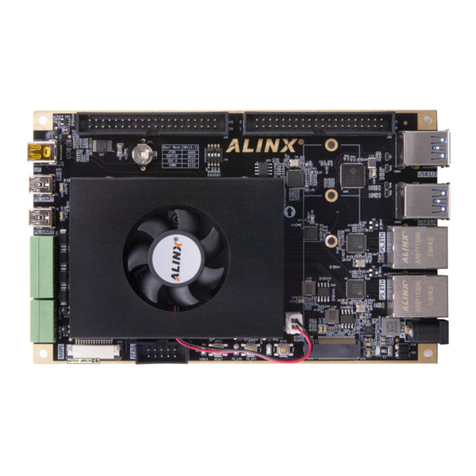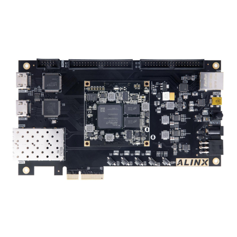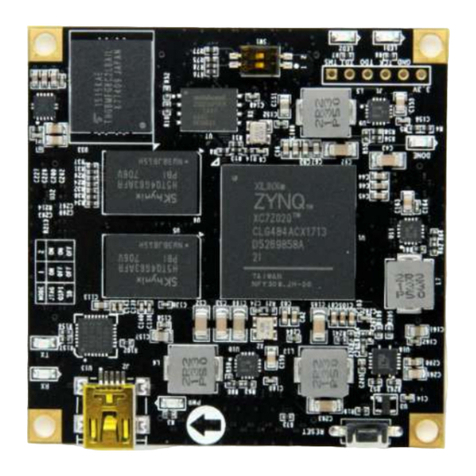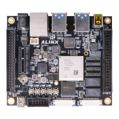
KINTEX-7 FPGA Development Board AV7K325 User Manual
Amazon Store: https://www.amazon.com/alinx
Table of Contents
Version Record.......................................................................................................2
Part 1: FPGA Development Board Introduction............................................... 6
Part 2: AC7K325 Core Board.............................................................................. 9
Part 2.1: AC7K325 Core Board Introduction............................................ 9
Part 2.2: FPGA Chip................................................................................... 10
Part 2.3:DDR3 DRAM.................................................................................11
Part 2.4: QSPI Flash...................................................................................15
Part 2.5: Clock configuration..................................................................... 17
Part 2.5.1: 200Mhz system clock source........................................17
Part 2.5.2: GTX Reference Clock.....................................................18
Part 2.6: LED Light......................................................................................19
Part 2.7: Power Supply...............................................................................20
Part 2.8: Size Dimension........................................................................... 23
Part 2.9: Board-to-Board Pin Definition...................................................23
Part 3: Carrier Board...........................................................................................32
Part 3.1: Carrier Board Introduction.........................................................32
Part 3.2: SFP Interface...............................................................................32
Part 3.3.: PCIe Card Slot........................................................................... 34
Part 3.4: HDMI Video Output Interface....................................................36
Part 3.5: HDMI Input Interface.................................................................. 41
Part 3.6: SATA Interface.............................................................................46
Part 3.7: USB to Serial Port.......................................................................47
Part 3.8: SD Card Slot................................................................................48
Part 3.9: 40-Pin Expansion Port............................................................... 49
Part 3.10: Keys and LEDs......................................................................... 50
Part 3.11: JTAG debug port.......................................................................52
Part 3.12: Power Supply............................................................................ 52

