manuals.online logo
Brands
  1. Home
  2. •
  3. Brands
  4. •
  5. Allsteel
  6. •
  7. Indoor Furnishing
  8. •
  9. Allsteel MERGE Service manual

Allsteel MERGE Service manual

Allsteel Inc.
Muscatine, Iowa 52761-0071
www.allsteeloffice.com
MERGEINST
343-1830C
(10/11)
MERGE Installation Packet
Index
Base Positions Standard Leg ...............................Page 1 thru 4
Power Caddy and Wire Manager ...........................Page 5
Lift and Release Post Leg Table.............................Page 6
Adaptive Table ..........................................Page 7 and 8
Height Adjustable X-base Tables ............................Page 9
Power Bay Table.........................................Page 10 thru 13
Power Wedge and Wire Manager............................Page 14
343-1830C
PAGE 1 OF 14 (10/11)
MERGE ACCESSORIESMERGE STANDARD LEG ASSEMBLY
Illustration 1. Base Positions
343-1830C
PAGE 2 OF 14 (10/11)
MERGE ACCESSORIESMERGE STANDARD LEG ASSEMBLY
1. Align holes in top plate
with bosses in extrusion.
2. Using #3 Phillips driver,
insert (4) 1/4 - 20 flathead
screws through top plate
into bosses in extrusion.
1. Align holes in top plate
with bosses in extrusion.
2. Using #3 Phillips driver,
insert (2) 1/4 - 20 flathead
screws through top plate
into bosses in extrusion.
Illustration 2. Large T-bases
1. Align holes in top plate
with bosses in extrusion.
2. Using #3 Phillips driver,
insert (2) 1/4 - 20 flathead
screws through top plate
into bosses in extrusion.
Illustration 4. For outboard mounting of Small and
Medium T-bases
Illustration 3. Small and Medium T-bases
1. Align holes in base with
bosses in extrusion.
2. Using a 7/16” hex driver,
insert (4) hex head
screws through base into
bosses in extrusion.
3. Align holes in top plate
with bosses in extrusion.
4. Using #3 Phillips driver,
insert (4) 1/4 - 20 flathead
screws through top plate
into bosses in extrusion.
Illustration 5a. X bases and Disc base (seated and
standing height)
IMPORTANT: Do not use impact
gun for installation of screws into
extrusion. Torque not to exceed
65 - 70 in-lbs.
IMPORTANT: Do not use impact
gun for installation of screws into
extrusion. Torque not to exceed
65 - 70 in-lbs.
IMPORTANT: Do
not use impact gun
for installation of
screws into extrusion.
Torque not to exceed
65 - 70 in-lbs.
IMPORTANT: Do not use impact
gun for installation of screws into
extrusion. Torque not to exceed
65 - 70 in-lbs.
343-1830C
PAGE 3 OF 14 (10/11)
MERGE ACCESSORIESMERGE STANDARD LEG ASSEMBLY
1. Align holes in top plate
with bosses in extrusion.
2. Using #3 Phillips driver,
insert (4) 1/4 - 20
flathead screws through
top plate into bosses in
extrusion.
Illustration 5b. Powered X bases and Disc base
(seated and standing height)
1. Align holes in base with bosses
in extrusion.
2. Using a 7/16” hex driver, insert
(4) hex head screws through
base into bosses in extrusion.
3. Align holes in offset top plate
with bosses in extrusion. Be
sure slot in offset top plate is
aligned with the wire channel
in the extrusion.
4. Using #3 Phillips driver, insert
(4) 1/4 - 20 button head screws
through offset top plate into
bosses in extrusion.
5. DO NOT snap on raceway
cover at this time.
Illustration 6a. Post Leg to worksurface
1. Align holes in top plate with (2)
pilot holes in worksurface as
shown by dashed lines.
2. Using #2 Phillips driver, insert
(2) #10 x 1” flathead screws
through top plate into pilot holes
in worksurface.
3. Using #2 Phillips driver, insert
remaining 6 - #10 x 1” flathead
screws.
4. Repeat steps 1 through 3 for the
remaining legs.
Illustration 6b. X bases and Disc base to
worksurface
These hole patterns
for use with post legs
See Instructions for (6a).
Illustration 6c. Powered X base and Disc to
worksurface
1. Align holes in offset top plate with (8) pilot holes in
worksurface as shown by dashed lines.
2. Using #3 Phillips driver, insert (8) #10 x 1” panhead wood
screws into pilot holes in worksurface.
IMPORTANT: Do not
use impact gun for
installation of screws into
extrusion. Torque not to
exceed 65 - 70 in-lbs.
343-1830C
PAGE 4 OF 14 (10/11)
MERGE ACCESSORIESMERGE STANDARD LEG ASSEMBLY
Illustration 6d. Counterweight kit option for Disc
base and Powered Disc base
1. Orient base ass-
embly as shown.
2. Set (8) ballast
plates in place,
aligning central
plate holes with
drilled and tapped
holes in Disc base.
3. Using a #3 Phillips
driver, insert (8) 1/4
- 20 x 5/8” button
head screws into
drilled and tapped
holes in Disc base.
Illustration 6e. T base to worksurface
See Instructions for (6a).
NOTE: If Stretcher Bar is required,
complete instructions in
Illustration 6d prior to
attaching the leg assembly
to the worksurface.
Illustration 6f. Stretcher bar option for Large T
base
1. Connect Stretcher Bar Brackets to Legs using a 1/4” Hex
Head Driver (a driver extension will be necessary) and
Self-Drilling 1” Screws as shown.
2. Attach the Stretcher Bar to the Stretcher Bar Brackets
using a 1/4” Hex Head Driver and Self-Drilling 1” Screws.
Fasteners will be hidden in the downward facing fastener
channel.
3. Repeat for other end
6.227”
Reference
Dimension
343-1830C
PAGE 5 OF 14 (10/11)
MERGE ACCESSORIESMERGE POWER CADDY AND WIRE MANAGER ASSEMBLY
Illustration 1a. Pop-Up Power Caddy Installation
1. Orient Pop-up Power Caddy so cord points in the
direction of the slot in the Offset Top Plate.
2. Feed Pop-up Power Caddy cord through hole in
worksurface and slot in Offset Top Plate.
3. See Pop-Up Power Caddy Instructions for metal spring
spacer placement.
Illustration 1b. Pop-up Power Caddy Installation
1. Coil enough cord between Pop-up Power Caddy and
Offset Top Plate to allow Pop-up Power Caddy to function
properly (no coil will lead to nonfunctioning Power Caddy).
2. Test pop-up function of Power Caddy. If Caddy does not
completely open, adjust amount of coiled cord until pop-up
function is smooth.
Illustration 1c. Pop-up Power Caddy Installation
1. Once function of Pop-up Power Caddy has been confirmed:
Illustration 1d. Pop-up Power Caddy Installation
1. See Pop-up Power Caddy instruction for metal spring
spacer placement and plastic retainer clip installation.
2. To install Pop-Up Power Caddy:
Cord direction
Slot in Offset
Top Plate
Raceway
channel
Raceway
cover
Coiled Cord
Pop-Up Caddy
assembled in
worksurface
C
B
A
• A. Make sure cord is tucked into extrusion’s Raceway channel.
• B. Feed cord through mouse hole.
• C. Snap Raceway cover into Raceway channel. • A. Route Pop-Up Power Caddy cord, set Power
Caddy into hole in worksurface.
• B. If using a Merge Wire Manager, run cord along
underside of worksurface, then down leg (T-base shown).
• C. Hold cord against leg and snap Wire Manager onto
leg (per instructions on page 14).
A
B
C
343-1830C
PAGE 6 OF 14 (10/11)
MERGE ACCESSORIESMERGE LIFT AND RELEASE POST LEG TABLE
Illustration 1. Assembly Instructions
Safety mechanism information:
- Lift and release legs contain
an integral safety mechanism.
- This mechanism is weight
activated.
- The height adjustment
mechanism will not operate
until the levers are depressed
and the worksurface lifted to
remove the load on the height
adjustment mechanism.
- The levers must be depressed
prior to removing the load
from the mechanism.
Illustration 2. Instructions for Use and Safety Mechanism Information
To raise table:
- Squeeze levers on one end of the
table.
- Raise table to desired height.
- Release levers.
- Lower worksurface until mechanism
clicks into place.
- Repeat for other end.
To lower table:
- Squeeze levers on one end of table.
- Slightly raise table to remove load
from mechanism.
- Lower table to desired height.
- Release levers.
- Lower worksurface until mechanism
clicks into place.
- Repeat for other end.
Levers
Levers
See Illustration 6a on page 3.
343-1830C
PAGE 7 OF 14 (10/11)
MERGE ACCESSORIESMERGE ADAPTIVE TABLE
Illustration 1. Assembly Instructions 1. Ensure area is clear of any debris
that could scratch the worksurface.
2. Place the main and leaf worksurfaces
face down on a clean surface. Orient
the worksurfaces as shown to create
a 36” round or square table.
3. Make sure the worksurfaces are
pressed together to minimize the
gap. Use the pilot holes to position
the hinge mechanisms and attach
each hinge mechanism using (5)
#10 x 1” panhead wood screws as
shown.
Required tools:
#3 Phillips Driver
Illustration 2. Assembly Instructions
4. Place the base assembly on the table as shown.
See Illustration 3 on page 5 for Pull Cable Routing.
NOTE: The base assembly will have a round or
square label indicating use with a round or square
table.
5. Use the pilot holes to locate the slide angle
brackets and attach using the #10 x 1” panhead
wood screws. Five screws are used to attach each
bracket. Extend the slides to gain access to the two
front inner screw locations.
6. Use the pilot holes to locate the linkage pivot and
attach using two #10 x 1” panhead wood screws.
7. Use the pilot holes to locate the pull handle and
attach using three #10 x 1” panhead wood screws.
8. Set table upright on casters.
Main worksurface
Hinge mechanisms
Leaf
worksurface
Linkage pivot
Slide angle
brackets
Label
Pull handle
343-1830C
PAGE 8 OF 14 (10/11)
MERGE ACCESSORIESMERGE ADAPTIVE TABLE
Illustration 3. Assembly Instructions
Bottom view of assembled table.
Top view showing cable routing
9. Raise and lower the table three times to lubricate the cylinder. To raise,
activate the pull handle, the table will automatically rise. To lower, push
down in the middle of the table with the pull handle activated.
NOTE: The cylinder may be “frozen” from shipping, if the table does not rise
with pull handle activated, push down in the center of the table with the pull
handle activated.
10.Fold the leaf worksurface by squeezing the hinge mechanism handles. To
raise, rotate the leaf to the horizontal position.
NOTE: Bumpers are included for use when the adaptive table is nested
under other surfaces. Position bumpers as required to prevent scratching.
Hinge Mechanism
Handle
Pull Handle
343-1830C
PAGE 9 OF 14 (10/11)
MERGE ACCESSORIESMERGE HEIGHT ADJUSTABLE X-BASE TABLE
Top view showing cable routing
Illustration 1. Assembly Instructions
Illustration 2. Assembly Instructions
4. Use (8) pilot holes in worksurface to locate the
welded plate.
5. Attach base and Pull Cable handle using (11)
#10 x1” panhead wood screws.
6. Set table upright on casters.
7. Raise and lower the table three times to lubricate
the cylinder. To raise, activate the pull handle,
the table will automatically rise. To lower, push
down in the middle of the table with the pull
handle activated.
NOTE: The cylinder may be “frozen” from
shipping, if the table does not rise with pull
handle activated, push down in the center of the
table with the pull handle activated.
Cable arc
must lie
“within” the
worksurface’s
milled recess.
Pay extra attention to path of Pull Cable
Milled recess
Base tilted back to allow proper cable routing
Welded plate
through
holes (8)
1. Check that area is clear
of any debris that could
scratch the worksurface.
NOTE: The base assembly
will have a label displaying
a 1 or 2. The worksurface
paired with the base must
have the same label.
2. Place the base assembly
on the table as shown
below. Route Pull Cable
EXACTLY as illustrated.
NOTE: Base orientation
on 30” Conference Corner
worksurfaces is inten-
tionally rotated 45
to
improve stability.
3. Be very careful to maintain
the cable curvature shown
as base is rotated down to
rest completely on work-
surface bottom.
343-1830C
PAGE 10 OF 14 (10/11)
MERGE ACCESSORIESMERGE POWER BAY TABLE
Required Tools:
• #3 Phillips Driver
• #2 Phillips Driver
• 1/4” Hex Head Driver
• 7/16” Driver
• Clamps
Illustration 1. Power Bay Table Assembly Instructions
Illustration 2. Power Bay Table Assembly Detail A
DETAIL B
DETAIL A
Stretcher Bar
Bracket
Large T-Base
Assembly
Rail/Trough
Assembly
1. Connect Stretcher Bar Brackets to
Legs using a 1/4” Hex Head Driver (a
driver extension will be necessary)
and Self-Drilling 1” Screws as shown
in Detail A.
2. Attach the Stretcher Bar to the
Stretcher Bar Brackets using a
1/4” Hex Head Driver and Self-
Drilling 1” Screws. Fasteners
will be hidden in the downward
facing fastener channel.
3. Repeat for other end.
Hex Washer Head Self Drilling Screw
1/4” Driver
Large T-Base
Extrusion
Stretcher Bar
Bracket
Hex Washer Head Self Drilling Screw
1/4” Driver
Stretcher Bar
6.227”
Reference
Dimension
Stretcher Bar
343-1830C
PAGE 11 OF 14 (10/11)
MERGE ACCESSORIESMERGE POWER BAY TABLE
Illustration 3. Power Bay Table Assembly Detail B
Illustration 4. Power Bay Table Assembly
4. Position Leg/Stretcher Bar Assembly rightside
up. Set Rail/Trough Assembly on top of Leg/
Stretcher Bar Assembly. Connect the Leg/
Stretcher Bar Assembly to the Rail/Trough
Assembly using a 7/16” Driver and 1-1/4” Hex
Washer Head Screws (4) as shown in Detail B.
Repeat at opposite end.
Rail/Trough
Assembly
1/4 - 20 Tap Bolt
7/16” Driver
Large T-Base
Extrusion
5. Place End Worksurface on Leg/Rail/Trough
Assembly and position so that the screw
inserts in the worksurface are centered in
the holes in the Leg/Rail/Trough
Assembly Frame Plate.
6. Attach the End Worksurface loosely
to the Leg/Rail/Trough Assembly
using a #3 Phillips Driver and
1/4 - 20 x 3/4” Pan Head Machine
Screws (4).
7. Repeat for second End Worksurface.
Frame
Plate
End
Worksurface
Leg/Rail/Trough
Assembly
IMPORTANT: Do
not use impact gun
for installation of
screws into extrusion.
Torque not to exceed
65 - 70 in-lbs.
343-1830C
PAGE 12 OF 14 (10/11)
MERGE ACCESSORIESMERGE POWER BAY TABLE
Illustration 5. Power Bay Table Assembly
8. Position the Slide Assembly so the bracket with
the tab is located under the End Worksurface.
Center the holes in the bracket with the screw
inserts in the worksurface. Use a #3 Phillips
Driver and 1/4 - 20 x 3/4” Pan Head Machine
Screws (2) to tightly connect the Slide Assembly
to the End Worksurface. Repeat for remaining
three Slide Assemblies.
9. Set the Middle Worksurface into place between
the End Worksurfaces. If worksurfaces are
veneer, be sure to orient the worksurfaces so
that the sets stay matched. Center the holes
in the Slide Assemblies with the screw inserts
in the Middle Worksurface and loosely attach
using a #3 Phillips Driver and 1/4 - 20 x 3/4” Pan
Head Machine Screws (2). Repeat for second
Middle Worksurface.
Slide
Assembly
End
Worksurface
Middle
Worksurface
Leg/Rail/Trough
Assembly
Veneer Matched Sets will be marked as shown
Slide Assembly
Tab
343-1830C
PAGE 13 OF 14 (10/11)
MERGE ACCESSORIESMERGE POWER BAY TABLE
Illustration 6. Power Bay Table Assembly
Illustration 8. Power Bay Table Assembly Detail D
Illustration 7. Power Bay Table Assembly Detail C
10. Adjust the End and Middle
Worksurfaces so the outer edges
are aligned and the spacing
between the worksurfaces is even.
Make sure the Slide Assemblies are
in the fully closed position. Clamp
the End and Middle Worksurfaces to
maintain position.
11. Tighten machine screws that
were loosely connecting the
Slide Assemblies to the Middle
Worksurfaces. Also tighten the
machine screws connecting the End
Worksurfaces to the Leg/Rail/Trough
Assembly Frame Plates. Install #2 x
1” Pan Head Wood Screws using a
#3 Phillips Driver into smaller holes
in Slide Assembly Brackets and Leg/
Rail/Trough Assembly Frame Plates
for added worksurface rigidity.
Remove clamps from worksurfaces.
12. Attach the Slide Covers (4) to the Middle worksurfaces
using a #2 Phillips Driver and #8 x 1/2” Flattened Pan
Washer Head Screws (8).
13. Using a 1/4” Hex Head Driver and 1” Self-Drilling Screws
(4), connect the four Slide Assembly Tabs to the Rails.
Middle
Work Surface
End
Work Surface
Slide
Assembly
DETAIL C
Leg/Rail/Trough
Assembly
Frame
Plate
End
Worksurface
Slide
Assembly
Tab
Roller Support
Assembly
Rail
DETAIL D
Rail
Slide
Assembly Hex Washer Head
Self-Drilling Screw
Middle
Worksurface
#8 x 1/2” Flattened
Pan Washer Head Screw
Slide Cover
Middle
Worksurface
Hex Washer Head
Self-Drilling Screw
14. Connect the Roller Support Assemblies (2) to the Rails
using a 1/4” Hex Head Driver and 1” Self-Drilling Screws
(4). The Roller Support Assemblies must be oriented so
that the roller is touching the bottom of the worksurface.
343-1830C
PAGE 14 OF 14 (10/11)
MERGE ACCESSORIESMERGE POWER WEDGE AND WIRE MANAGER
Illustration 1. Power Wedge Instructions
1. Align Power Wedge with desired Power Wedge location
(two slots on Power Bay bottom, one hole in Power Bay
vertical wall).
2. Insert Power Wedge tabs into Power Bay bottom slots and
Power Wedge threaded stud through hole in Power Bay
vertical wall.
3. Screw thumb nut onto Power Wedge threaded stud to hold
Power Wedge securely in place.
Illustration 1a. Cut Away View
4. Run Power Wedge cord through open area in Power Bay
vertical end wall. A Merge Wire Manager can be used to
neatly contain the Power Wedge cord against the table’s
leg.
NOTE: Some Power Bay table components have been
removed for clarity
Illustration 1b. Power Wedge Cord
Power Wedge
threaded stud
Power Wedge
thumb nut
Power Bay
vertical wall hole Power Bay
bottom slot
Power Wedge
tab
Power Bay
vertical wall hole
Power
Wedge cord Merge Power Wedge
Merge Wire Manager
Power Bay
bottom slots
Illustration 2. Wire Manager Instructions
1. Align Wire Manager bottom with the junction between the
vertical extrusion and the leg base.
2. Be sure that Power Wedge cord is completely contained
within the Wire Manager.
Illustration 2a. Wire Manager
3. Place one edge of the Wire Manager flat against the
vertical extrusion. Press the center of the Wire Manager
until the other edge snaps into place.
Illustration 2b. Top View
Wire Manager
Wire Manager
bottom
junction
leg base
vertical extrusion
vertical extrusion
Power Wedge cord
Press here.
Wire Manager
This
side
will
snap
into
place.

Other Allsteel Indoor Furnishing manuals

Allsteel Park Series User manual

Allsteel

Allsteel Park Series User manual
Allsteel GZCKP User manual

Allsteel

Allsteel GZCKP User manual
Allsteel Further Series User manual

Allsteel

Allsteel Further Series User manual
Allsteel Access User manual

Allsteel

Allsteel Access User manual

Allsteel Park NA96RCF User manual

Allsteel

Allsteel Park NA96RCF User manual

Allsteel Laminate Casegoods User manual
Allsteel

Allsteel Laminate Casegoods User manual

Allsteel Approach User manual

Allsteel

Allsteel Approach User manual
Allsteel Further User manual

Allsteel

Allsteel Further User manual
Allsteel Park User manual

Allsteel

Allsteel Park User manual
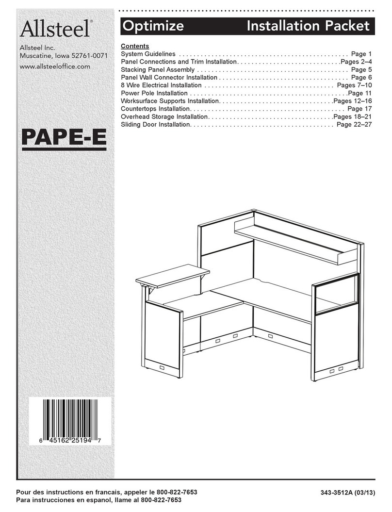
Allsteel Optimize Service manual

Allsteel

Allsteel Optimize Service manual

Allsteel Universal Screens User manual
Allsteel

Allsteel Universal Screens User manual

Allsteel All-Around Table User manual

Allsteel

Allsteel All-Around Table User manual

Allsteel Quip User manual

Allsteel

Allsteel Quip User manual

Allsteel Townhall Series User manual

Allsteel

Allsteel Townhall Series User manual
Allsteel A8 User manual

Allsteel

Allsteel A8 User manual

Allsteel Trooper User manual

Allsteel

Allsteel Trooper User manual
Allsteel Harvest Rustic Standing Height Table User manual

Allsteel

Allsteel Harvest Rustic Standing Height Table User manual

Allsteel Terrace DNA User manual

Allsteel

Allsteel Terrace DNA User manual
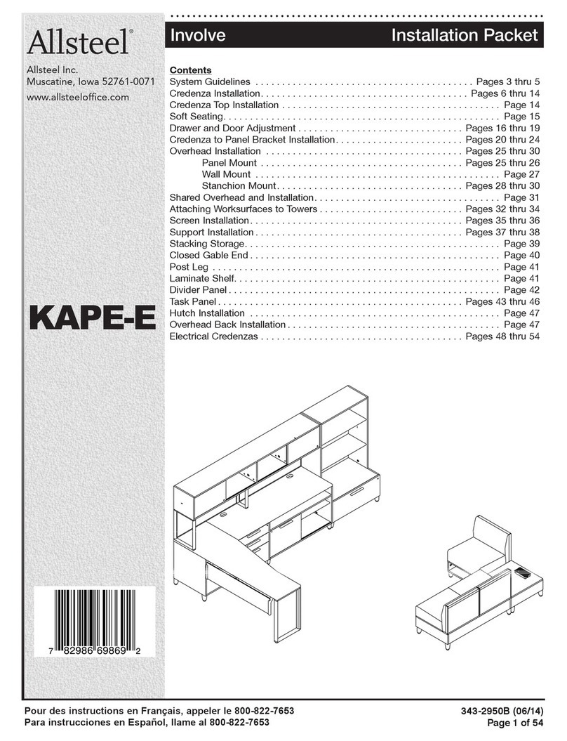
Allsteel Involve KAPE-E Service manual
Allsteel

Allsteel Involve KAPE-E Service manual

Allsteel Mind-Share Service manual

Allsteel

Allsteel Mind-Share Service manual

Allsteel Harvest User manual

Allsteel

Allsteel Harvest User manual

Allsteel CONCENSYS CAPE User manual

Allsteel

Allsteel CONCENSYS CAPE User manual

Allsteel Cadence Applica Freestanding Desk User manual

Allsteel

Allsteel Cadence Applica Freestanding Desk User manual

Allsteel Park Easel Service manual

Allsteel

Allsteel Park Easel Service manual

Popular Indoor Furnishing manuals by other brands
Kinnarps WORKS DS Assembly instructions

Kinnarps

Kinnarps WORKS DS Assembly instructions

milliard MIL-XCHR-IV manual

milliard

milliard MIL-XCHR-IV manual

Ergonomic Seating Solutions OPERA 50 instructions

Ergonomic Seating Solutions

Ergonomic Seating Solutions OPERA 50 instructions

IKEA IBESTAD instructions

IKEA

IKEA IBESTAD instructions

Trinity EcoStorage THA-3328 owner's manual

Trinity

Trinity EcoStorage THA-3328 owner's manual

AMQ Revi installation guide

AMQ

AMQ Revi installation guide

Homelegance 1525-1 Assembly instruction

Homelegance

Homelegance 1525-1 Assembly instruction

ohcielos 6036 Assembly instructions

ohcielos

ohcielos 6036 Assembly instructions

Triarch 31431-35 Assembly instructions

Triarch

Triarch 31431-35 Assembly instructions

Twoey 1100 Assembly instructions

Twoey

Twoey 1100 Assembly instructions

Galipette 405 manual

Galipette

Galipette 405 manual

Bedz King BK551 manual

Bedz King

Bedz King BK551 manual

DIY BBQ TV-Chimney Module instruction manual
DIY BBQ

DIY BBQ TV-Chimney Module instruction manual

CB2 GLOSS Assembly instructions

CB2

CB2 GLOSS Assembly instructions

Clou mini match me CL/07.56.402.50 installation instructions
Clou

Clou mini match me CL/07.56.402.50 installation instructions

PARAMOUNT BED PS-0232S instruction manual

PARAMOUNT BED

PARAMOUNT BED PS-0232S instruction manual

J.Burrows JBTOCR12GY Assembly instructions
J.Burrows

J.Burrows JBTOCR12GY Assembly instructions

Allen + Roth SERENA PARK LOVESEAT FRS90466 quick start guide

Allen + Roth

Allen + Roth SERENA PARK LOVESEAT FRS90466 quick start guide

manuals.online logo
manuals.online logoBrands
  • About & Mission
  • Contact us
  • Privacy Policy
  • Terms and Conditions

Copyright 2025 Manuals.Online. All Rights Reserved.