manuals.online logo
Brands
  1. Home
  2. •
  3. Brands
  4. •
  5. Allsteel
  6. •
  7. Indoor Furnishing
  8. •
  9. Allsteel Cadence Applica Freestanding Desk User manual

Allsteel Cadence Applica Freestanding Desk User manual

0430060100H
Page 1 of 8 (05/2020)
Cadence™FREESTANDING DESK APPLICA-
AT I O N I N S T R U CT I O N
Full end panel support
assembled for left-hand
application
Full end panel support
assembled for right-hand
application
INSTALLATION INSTRUCTIONS
Attachment bracket
Full end panel support
assembled for left-hand
application
Leveler
Machine screw
Attachment bracket
Machine screw
Leveler
Full end panel support
assembled for right-hand
application
WARNING
Failure to install product as instructed, use of hardware other than that which is provided with the
product, or failure to comply with all instructions can result in personal injury.
Illustration 1. Congure Full End Panel Support to a Left-Hand or Right-Hand Application
0430060100H
Page 2 of 8 (05/2020)
Cadence™FREESTANDING DESK APPLICA-
Illustration 2. Primary Desk with Modesty Panel
Step 3 - Wood screws
(three per
modesty panel,
at each end
and at center
location):
Install through
top flange
of modesty
panel and into
worksurface.
Step 1 - Machine screw (three per
full end panel support):
Install into worksurface
Step 2 - Sheet metal screws (three per side of modesty panel): Install
through modesty panel and into full end panel supports.
Full end panel support
Worksurface
Modesty panel
Cadence™ worksurfaces, full end panel supports, and modesty panels can be configured as freestanding desks.
For ease of assembly, assemble unit upside down onto cardboard or a carpeted surface.
0430060100H
Page 3 of 8 (05/2020)
Cadence™FREESTANDING DESK APPLICA-
Illustration 3. Primary Desk with Gussets
Step 3 - Wood screws
(three per
gusset): Install
through top
flange of
gusset and into
worksurface.
Step 1 - Machine screw (three per
full end panel support):
Install into worksurface
Step 2 - Sheet metal screws (two per gusset): Install
through gusset and into full end panel supports.
Full end panel support
Worksurface
Gusset - Position rear edge
of gusset 17/8" from rear
edge of worksurface (gusset
should run parallel with rear
edge of worksurface.)
Cadence™ worksurfaces, full end panel supports, and gussets can be configured as freestanding desks. For ease
of assembly, assemble unit upside down onto cardboard or a carpeted surface.
Note: Dependent on user preference, cosmetic
side (flat side) of gusset can face either front
or rear edge of worksurface.
0430060100
Page 4 of 8 (05/2020)
Cadence™FREESTANDING DESK APPLICA-
Illustration 4. Bridge and Return Attachment
Illustration 4a. Attach Modesty Panel Bracket
Step 1 - Place primary desk upside down onto cardboard or a carpeted surface.
Step 2 - On side of primary desk that bridge or return is to be attached, position modesty panel bracket against interior surface
of full end panel support.
If assembling a U-shaped configuration with a peninsula, align holes in bottom flange of modesty panel bracket with
the first pair of holes in bottom of full end panel support.
For all other configurations, align holes in bottom flange of modesty panel bracket with the second pair of holes in
bottom of full end panel support.
Step 3 - Install two sheet metal screws through holes in bottom flange of modesty panel bracket and into full end panel
support.
Step 4 - Install a wood screw through top flange of modesty panel bracket and into primary desk worksurface.
Step 5 - Remove front machine screw securing full end panel support to worksurface. Save screw for later use.
Note: If attaching bridge or return to a panel hung worksurface, attach modesty panel bracket to
full end panel support prior to attaching full end panel support to primary worksurface.
Primary desk
Wood screw
Second pair of holes - use
with all other configurations
Modesty panel
attachment bracket
Sheet metal screw
First pair of holes - use for
U-shaped configuration with
peninsula
Remove front machine
screw (save screw for
later use)
Cadence™FREESTANDING DESK APPLICA-
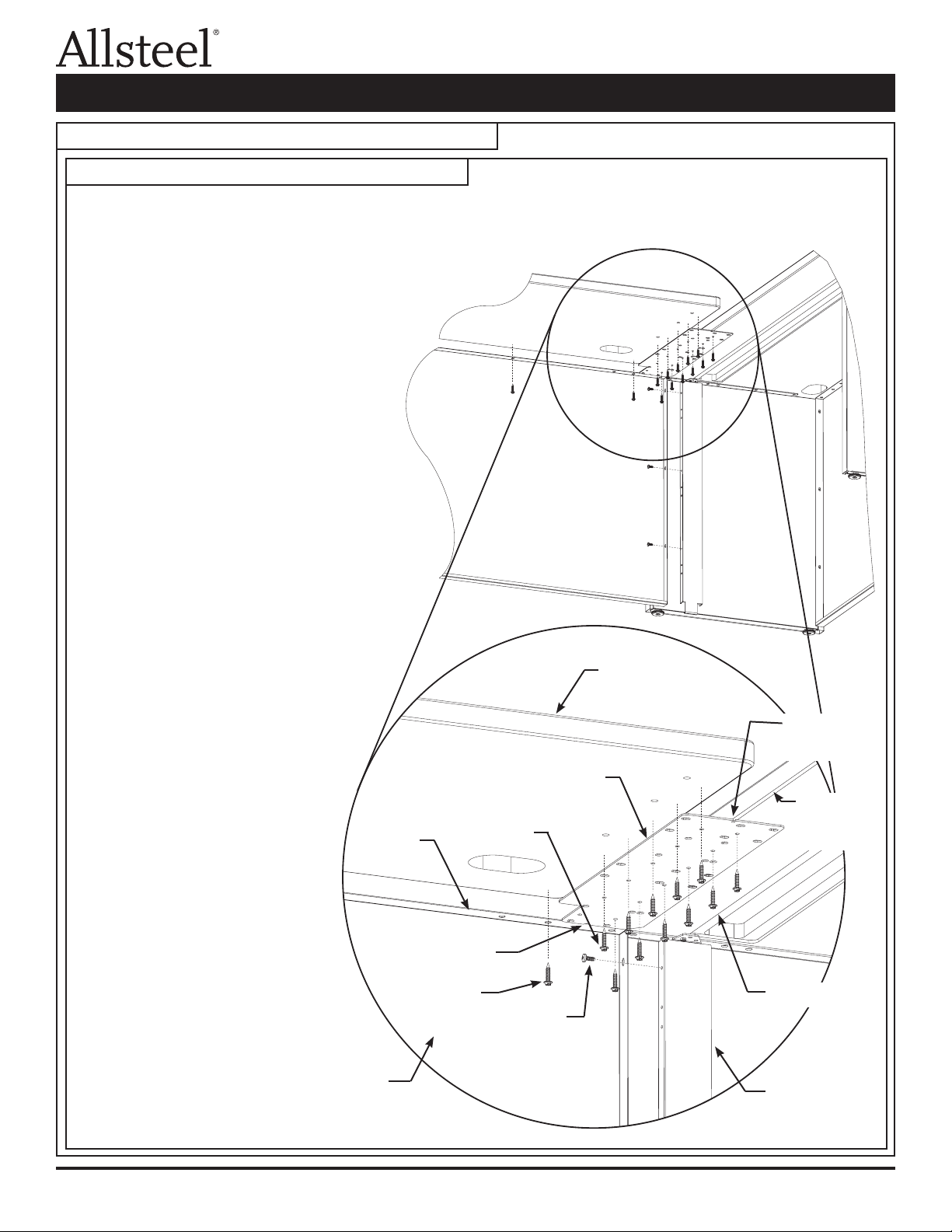
Illustration 4B. Attach Return or Bridge to Primary Desk:
1. Use three sheet metal screws to attach bridge modesty
panel to modesty panel bracket (attached to primary
desk full end panel support). Repeat procedure
at opposite end of modesty panel.
2. Attachaflat bracket to each primary desk
worksurface. Align center line locating notch
with front edge of primary worksurface and
rear edge with modesty panel top flange.
Attach each flat bracket with six wood
3. Position bridge worksurface onto flat brackets.
Check alignment of bridge worksurface with
each primary worksurface. Install six wood
screws through each flat bracket and into bridge
worksurface. Install wood screws through bridge
modesty panel (at each end and at center location)
and into bridge worksurface.
4. Reinstall machine screw removed in Illustration 4A.
1. Use three sheet metal screws to attach return
modesty panel to modesty panel bracket
(attached to primary desk full end panel sup-
port).Attachafull end panel support to
opposite end of modesty panel (refer to pri-
mary desk assembly instructions).
2. Attach flat bracket to primary desk work-
surface. Align center line locating notch
with front edge of primary worksurface
and rear edge with modesty panel top
flange. Attach flat bracket with six
3. Position return worksurface onto
flat bracket and full end panel
support. Attach full end panel
support to return worksurface
~
Illustration 4. Bridge and Return Attachment (continued)
Illustration 4b. Attach Return or Bridge to Primary Desk
Bridge Attachment:
Step 1 - Use three sheet metal screws to attach bridge modesty panel to modesty panel bracket (attached to primary desk full
end panel support). Repeat procedure at opposite end of modesty panel.
Step 2 - Attach a flat bracket to each primary desk worksurface.
Align center line locating notch with front edge of primary
worksurface and rear edge with modesty panel
top flange. Attach each flat bracket with six
wood screws.
Step 3 - Position bridge worksurface onto flat
brackets. Check alignment of bridge
worksurface with each primary
worksurface. Install six wood screws
through each flat bracket and into bridge
worksurface. Install wood screws through
bridge modesty panel (at each end and at
center location) and into bridge worksurface.
Step 4 - Reinstall machine screw removed in
Illustration 4a, Step 5.
Return Attachment:
Step 1 - Use three sheet metal screws to attach return
modesty panel to modesty panel bracket
(attached to primary desk full end panel
support). Attach a full end panel support to
opposite end of modesty panel (refer to
primary desk assembly instructions).
Step 2 - Attach flat bracket to primary desk
worksurface. Align center line locating
notch with front edge of primary
worksurface and rear edge with
modesty panel top flange.
Attach flat bracket with six
wood screws.
Step 3 - Position return worksurface
onto flat bracket and full end
panel support. Attach full end
panel support to return
worksurface with three
machine screws (refer to
primary desk assembly
instructions). Check alignment
of return worksurface with
primary worksurface and install
six wood screws through flat
bracket and into return worksurface.
Install wood screws through return
modesty panel (at each end and at
center location) and into return
worksurface.
Step 4 - Reinstall machine
screw removed in
Illustration 4a, Step 5.
Flat bracket
Wood screw
Return/bridge
worksurface
Modesty panel
bracket
Sheet metal
screw
Center line
locating notch
Front edge
of primary
worksurface
Wood screw
Wood screw
Return/bridge
modesty panel
Rear edge
Top flange
0430060100H
Page 5 of 8 (05/2020)
Illustration 5. Support Leg
Support leg
Machine screw
Flat bracket
Note: Use desk support legs to:
• Attach a bridge to a peninsula (refer
to Illustration 6).
• Attach a return or bridge to a corner
desk (refer to Illustration 7).
Notch – Position at rear and
shared worksurface side
of support leg. Flat bracket
should not interfere with
worksurface grommet.
•Bracket in image is shown in a right hand
orientation, For left hand orientation flip
bracket over.
Cadence™FREESTANDING DESK APPLICA-
0430060100
Page 6 of 8 (05/2020)
Illustration 6. Attach a Return or Bridge to a Peninsula Worksurface Using a Support Leg
Step 1 - Position support leg under
peninsula worksurface. Align
flat bracket center line locating
notch with front edge of
peninsula worksurface and
rear edge with modesty panel
top flange. Attach support
leg to peninsula worksurface
by installing two machine
screws through flat bracket
and into inserts in peninsula
worksurface.
Step 2 - Use three sheet metal screws to
attach peninsula modesty panel
to support leg.
Step 3 - Use three sheet metal screws
to attach return/bridge modesty
panel to opposite side of support
leg.
Step 4 - Position return/bridge
worksurface onto flat bracket.
Install two machine screws
through flat bracket and
into inserts in return/bridge
worksurface. Install wood screws
through return/bridge modesty
panel (at each end and at center
location) and into return/bridge
worksurface.
~
~
Wood screw
Support leg
Sheet metal screw
Flat bracket
Machine screw
Return/bridge modesty panel
Sheet metal
screw
Return/bridge
modesty panel
Peninsula
worksurface
Center line
locating notch
Return/bridge
worksurface
FREESTANDING DESK APPLICA-
Cadence™
0430060100H
Page 7 of 8 (05/2020)
0430060100H
Page 8 of 8 (05/2020)
Cadence™FREESTANDING DESK APPLICA-
Sheet metal screw
Sheet metal screw
Sheet
metal
screw
Wood screw
Wood screw
Corner desk support leg
Machine
screw
Machine
screw
Corner desk
worksurface
Corner desk modesty panel
Corner desk
modesty panel
Support leg
Wood
screw
Machine
screw
Corner
worksurface
Return worksurface
Return desk
Return desk
Center line
locating
notch
Flat
bracket
~~
~
~
Illustration 7. Corner Desk
Wood screw
Return desk
Return worksurface
Sheet
metal
screw
Center line
locating
notch
Support leg
Sheet metal screw
Flat
bracket
Corner desk
worksurface
Machine
screw
Return/bridge modesty panel
Step 1 - Assemble return desks using support legs under return desk side of worksurface.
Step 2 - Use three sheet metal screws to attach a corner desk modesty panel to each support leg.
Step 3 - Use six sheet metal screws to attach corner desk support leg to free ends of corner desk modesty panels.
Step 4 - Position corner desk worksurface onto flat brackets. Install two machine screws through each flat bracket and into
inserts in corner desk worksurface. Install two machine screws through each corner desk modesty panel and into
inserts in corner desk worksurface. Install wood screws through remaining holes in corner desk modesty panels and
into corner desk worksurface.
Corner
worksurface
Return desk
Machine
screw
Wood screw
Sheet metal screw
Corner desk support leg
Corner desk
modesty panel
Machine
screw
Wood
screw

Other Allsteel Indoor Furnishing manuals

Allsteel Optimize Service manual

Allsteel

Allsteel Optimize Service manual

Allsteel Townhall Series User manual

Allsteel

Allsteel Townhall Series User manual

Allsteel Trooper User manual

Allsteel

Allsteel Trooper User manual

Allsteel A8 User manual

Allsteel

Allsteel A8 User manual

Allsteel GZCKP User manual

Allsteel

Allsteel GZCKP User manual

Allsteel Harvest User manual

Allsteel

Allsteel Harvest User manual

Allsteel Laminate Casegoods User manual

Allsteel

Allsteel Laminate Casegoods User manual

Allsteel All-Around Table User manual

Allsteel

Allsteel All-Around Table User manual

Allsteel Terrace DNA User manual

Allsteel

Allsteel Terrace DNA User manual

Allsteel Park User manual

Allsteel

Allsteel Park User manual

Allsteel MERGE Service manual

Allsteel

Allsteel MERGE Service manual

Allsteel Park Series User manual

Allsteel

Allsteel Park Series User manual

Allsteel Park NA96RCF User manual

Allsteel

Allsteel Park NA96RCF User manual

Allsteel Quip User manual

Allsteel

Allsteel Quip User manual

Allsteel CONCENSYS CAPE User manual

Allsteel

Allsteel CONCENSYS CAPE User manual

Allsteel Harvest Rustic Standing Height Table User manual

Allsteel

Allsteel Harvest Rustic Standing Height Table User manual

Allsteel Approach User manual

Allsteel

Allsteel Approach User manual

Allsteel Involve KAPE-E Service manual

Allsteel

Allsteel Involve KAPE-E Service manual

Allsteel Access User manual

Allsteel

Allsteel Access User manual

Allsteel Further Series User manual

Allsteel

Allsteel Further Series User manual

Allsteel Further User manual

Allsteel

Allsteel Further User manual

Allsteel Mind-Share Service manual

Allsteel

Allsteel Mind-Share Service manual

Allsteel Universal Screens User manual

Allsteel

Allsteel Universal Screens User manual

Allsteel Park Easel Service manual

Allsteel

Allsteel Park Easel Service manual

Popular Indoor Furnishing manuals by other brands

Costway JV10874 manual

Costway

Costway JV10874 manual

Furniture of America Radnor CM4536C Assembly instructions

Furniture of America

Furniture of America Radnor CM4536C Assembly instructions

Forte CALPE CLPK21 Assembling Instruction

Forte

Forte CALPE CLPK21 Assembling Instruction

Gami 155 Assembly instructions

Gami

Gami 155 Assembly instructions

Coaster 610204P Assembly instructions

Coaster

Coaster 610204P Assembly instructions

Great Little Trading L5261 manual

Great Little Trading

Great Little Trading L5261 manual

RUSTA AMSTERDAM 605011640201 manual

RUSTA

RUSTA AMSTERDAM 605011640201 manual

Better Bathrooms Avebury BeBa 27033 user manual

Better Bathrooms

Better Bathrooms Avebury BeBa 27033 user manual

Profijt Meubel JONDAL DR6 Assembly instruction

Profijt Meubel

Profijt Meubel JONDAL DR6 Assembly instruction

StarTech.com STSCART instruction manual

StarTech.com

StarTech.com STSCART instruction manual

Triarch 31612 Assembly instructions

Triarch

Triarch 31612 Assembly instructions

Cooper Lighting 273 Series Specification sheet

Cooper Lighting

Cooper Lighting 273 Series Specification sheet

Costway HU10293 user manual

Costway

Costway HU10293 user manual

Tarrington House 221-0811 quick start guide

Tarrington House

Tarrington House 221-0811 quick start guide

Home Decorators Collection BRADSTONE JS-3424-A Use and care guide

Home Decorators Collection

Home Decorators Collection BRADSTONE JS-3424-A Use and care guide

Home Decorators 133-017-OT-PR Use and care guide

Home Decorators

Home Decorators 133-017-OT-PR Use and care guide

Baur 60704798 Assembly instructions

Baur

Baur 60704798 Assembly instructions

GALA MEBLE G60KSN Assembly manual

GALA MEBLE

GALA MEBLE G60KSN Assembly manual

manuals.online logo
manuals.online logoBrands
  • About & Mission
  • Contact us
  • Privacy Policy
  • Terms and Conditions

Copyright 2025 Manuals.Online. All Rights Reserved.