4
Der Sauerstoff ird zur Atmung genutzt, der Stickstoff ins Wasser ausgeschieden. Stickstoffgas
(N2) ist ein natürlicher Bestandteil der Luft und völlig unschädlich.
Beim Nitratabbau handelt es sich somit um einen reinen Atemvorgang. Zusätzlich benötigen die
Bakterien, genauso ie andere Lebe esen, Nahrung. Aus diesem Grunde müssen die
nitratabbauenden Bakterien gefüttert erden. Dieses Futter enthält organische Substanzen, die
von den Bakterien restlos ver ertet erden können. Als Abfallprodukt entsteht CO2.
Zur Fütterung im Nitratreductor können ent eder das Futter Denimar oder die Futterbälle
Deniballs genutzt erden.
Der Durchfluss durch den Nitratreductor geschieht äußerst langsam. Dies unterscheidet ihn von
herkömmlichen Aquarienfiltern, in denen das Wasser meist einmal pro Stunde oder noch öfter
gefiltert ird. Das Wasser sollte im Nitratreductor eine Aufenthaltszeit von enigstens vier Stunden
haben. Dafür reicht es aus, enn das Aquarien asser nur einmal pro Woche durch den Filter
geleitet ird. Ist der Filter richtig eingestellt, verlässt ihn das Wasser nahezu nitrat- und nitritfrei.
4. Auf au des Nitratreductors
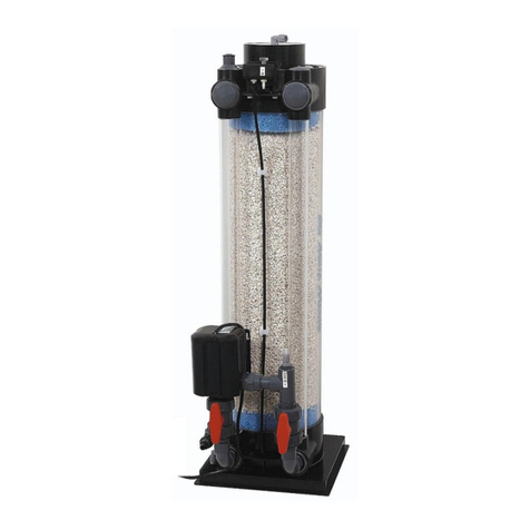
Der AB Aqua Medic Nitratreductor besteht aus einem Reaktionsbehälter (1) mit einem Volumen
von ca. 10 l. Als Auf uchsmaterial für die Bakterien erden AB Aqua Medic Bactoballs (2)
eingesetzt. Diese schaffen ein für die Denitrifikation ideales Mikroklima.
Zur Vermeidung toter Zonen ird das Wasser im Nitratreductor intern umge älzt. Dazu ist eine
Um älzpumpe (7) im Deckel untergebracht.
In Nitratfiltern ohne Durchmischung, insbesondere bei Geräten, in denen das Wasser eine lange
Fließstrecke zurücklegen muss, besteht die Gefahr, dass der Filter nicht gleichmäßig durchströmt
ird. Es bilden sich Zonen mit extrem niedrigem Redoxpotential und Sch efel asserproduktion
(der Filter beginnt unangenehm zu riechen). Auf der anderen Seite können Zonen mit zu starker
Durchströmung entstehen, o das Nitrat nur bis zum Nitrit reduziert ird. In jedem Fall herrschen
im Filter überall andere Reaktionsbedingungen, as die Einschätzung des Arbeitspunktes durch
Messung des Redoxpotentials unmöglich macht.
Im AB Aqua Medic Nitratreductor erden diese uner ünschten Effekte vermieden.
Die Um älzpumpe verhindert durch die gleichmäßige Durchmischung des Wassers im Filter die
Bildung von Nestern mit unterschiedlichen Redoxpotentialen.
Es herrschen überall gleiche Reaktionsbedingungen; das Redoxpotential im Filter kann zur
Steuerung herangezogen erden. Die Betriebssicherheit des Filters ird so gesteigert, und die
Möglichkeit der Vergiftung des Aquariums durch Nitrit ist eitestgehend ausgeschlossen.
Anschlüsse:
Im Deckel des Nitratreductors befinden sich die folgenden Anschlüsse:
1. Zulauf (5): Hier kann ein 6/4 mm Aquarienluftschlauch angeschlossen erden. Am Zulauf
befindet sich ein Einstellventil. Hier kann die Durchflussrate eingestellt erden. Der ideale Wert
beträgt ca. 1 - 1,5 l/Std. (ca. 1 Tropfen pro Sekunde). Die Steuerung über den Zulauf ist mit einer
ge issen Verzögerung verbunden, bis der eingestellte Durchfluss am Tropfenzähler (14) abzulesen
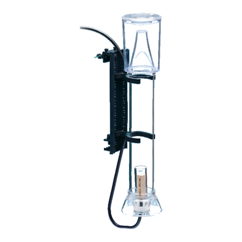
ist. Der Tropfenzähler ird mit Hilfe der Halteplatte (12 und 13) im Aquarium oberhalb des
Wasserspiegels angebracht. Wird der Durchfluss über den Ablauf geregelt, darf das Einstellventil
nicht vollständig geschlossen erden, damit entstandener Stickstoff aus dem System ent eichen
kann. Während der Einfahrphase ohne Wasserzulauf sollte man den Auslauf vollständig geöffnet
lassen.
Der Zulauf besitzt eine innenliegende Verlängerung, die verhindert, dass Gase in den Zulauf
steigen.
2. Futterzuga e (4): Durch diese Öffnung kann mit Hilfe einer Spritze das Denimar -Pulver zur
Steigerung der Denitrifikation hineingegeben erden. Man schlämmt das Pulver zuvor in einigen
Millilitern Wasser auf. Der Hahn ist nach jeder Futterzugabe mit Wasser zu spülen und anschließend
zu verschließen.
3. Redoxelektrode (17): In diese Öffnung kann eine druckfeste Redoxelektrode eingeschraubt
erden (nicht im Lieferumfang enthalten).


