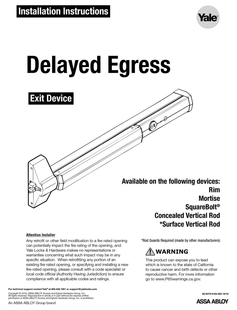
Assa Abloy Connect 50 User manual
Other Assa Abloy Door Lock manuals

Assa Abloy
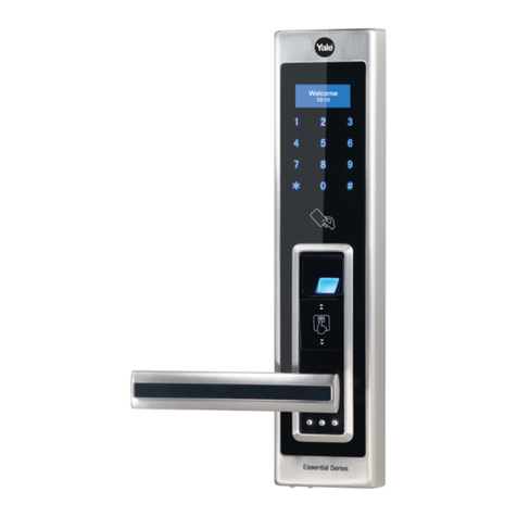
Assa Abloy Yale YDLL/BLK Troubleshooting guide
Assa Abloy
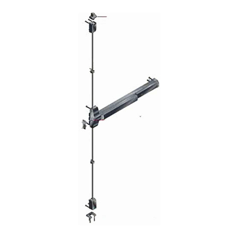
Assa Abloy Corbin Russwin FE5400S Series User manual
Assa Abloy
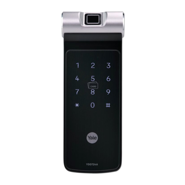
Assa Abloy Yale YDD724A User manual
Assa Abloy
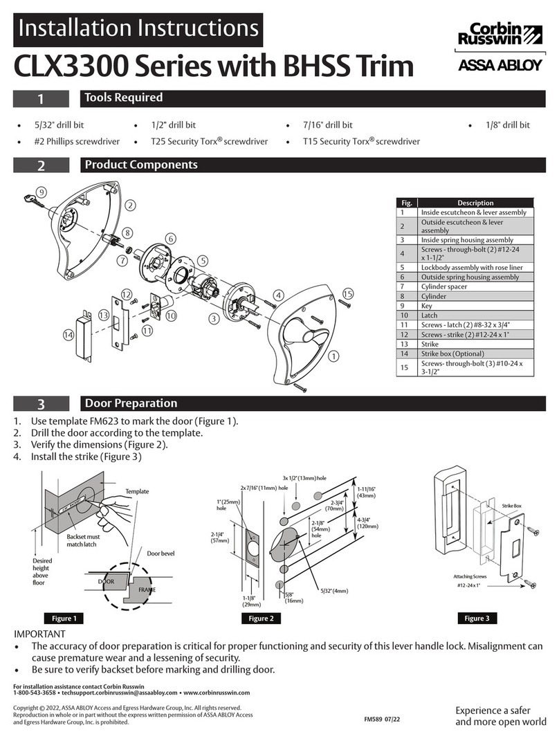
Assa Abloy Corbin Russwin CLX3300 Series User manual

Assa Abloy
Assa Abloy 8788 User manual
Assa Abloy
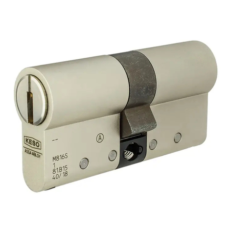
Assa Abloy KESO User manual
Assa Abloy
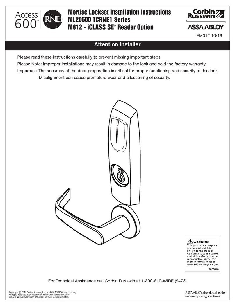
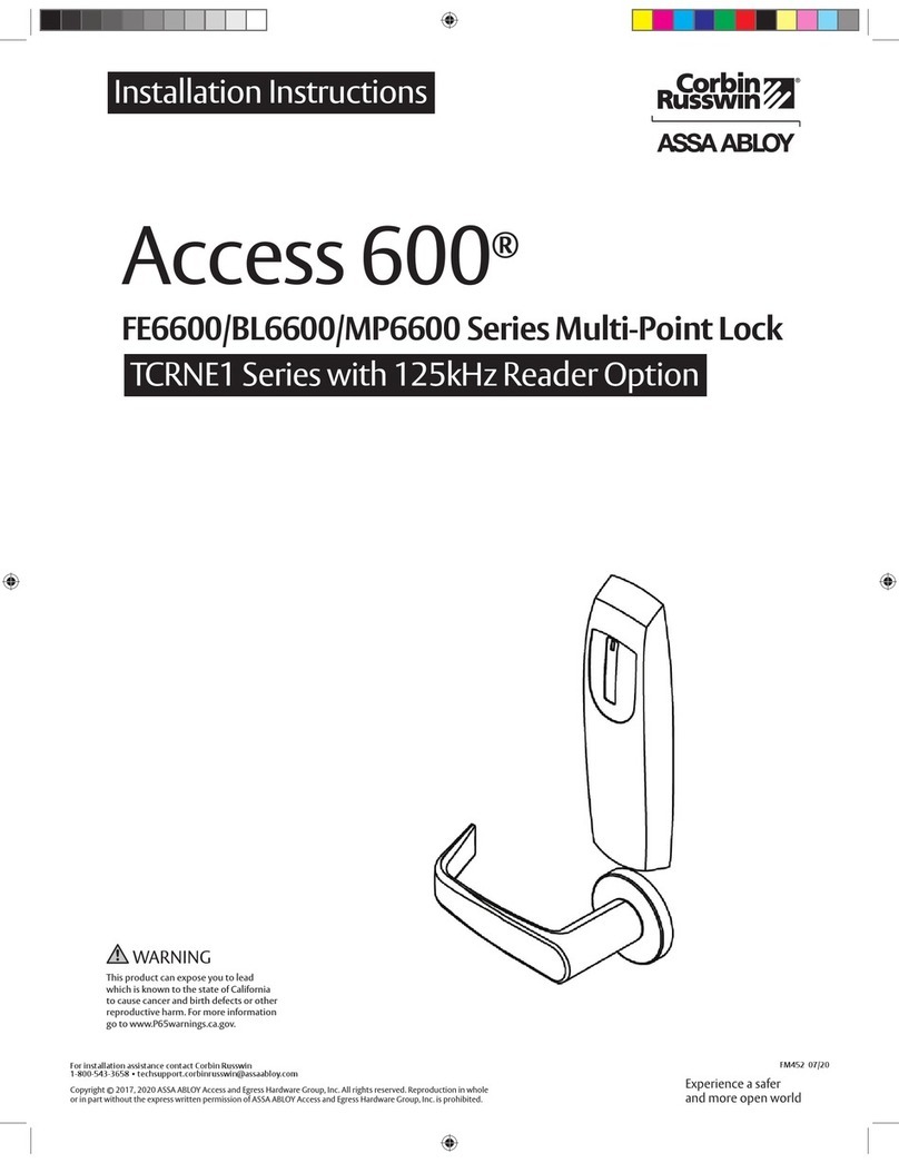
Assa Abloy Corbin Russwin Access 600 TCRNE1 Series User manual
Assa Abloy
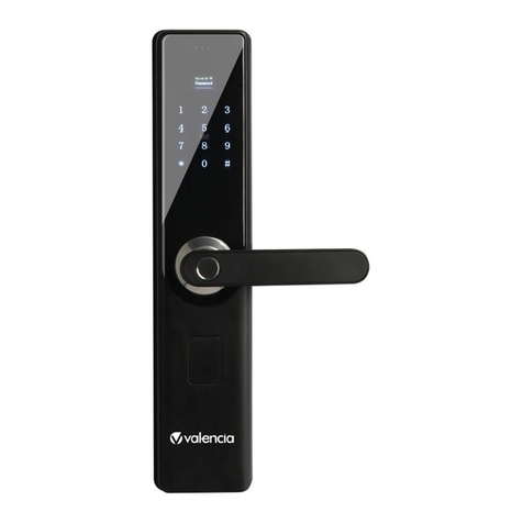
Assa Abloy Valencia AJAX User manual
Assa Abloy
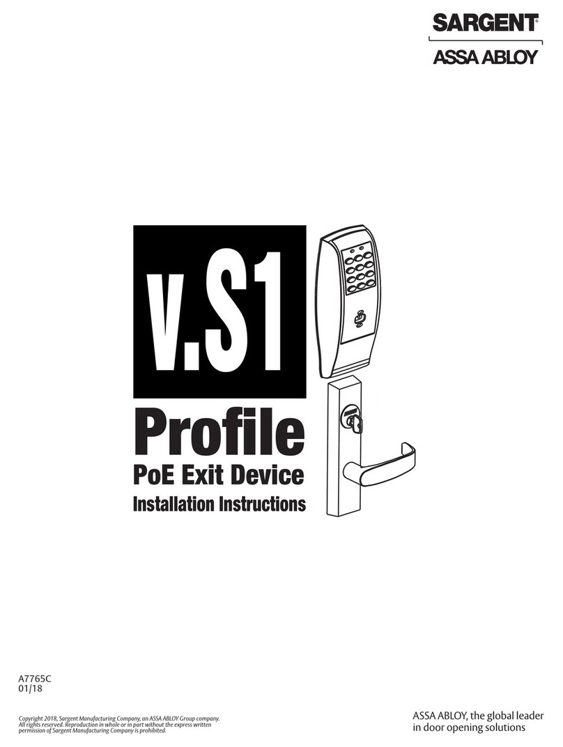
Assa Abloy SARGENT Profile Series User manual
Assa Abloy
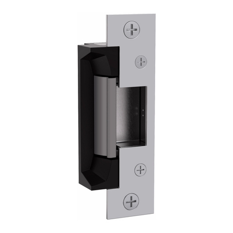
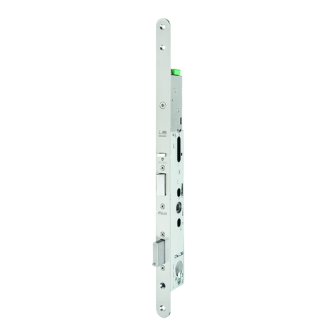
Assa Abloy Hes 5200 Series User manual
Assa Abloy
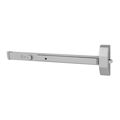
Assa Abloy MSL sFlipLock drive User manual
Assa Abloy
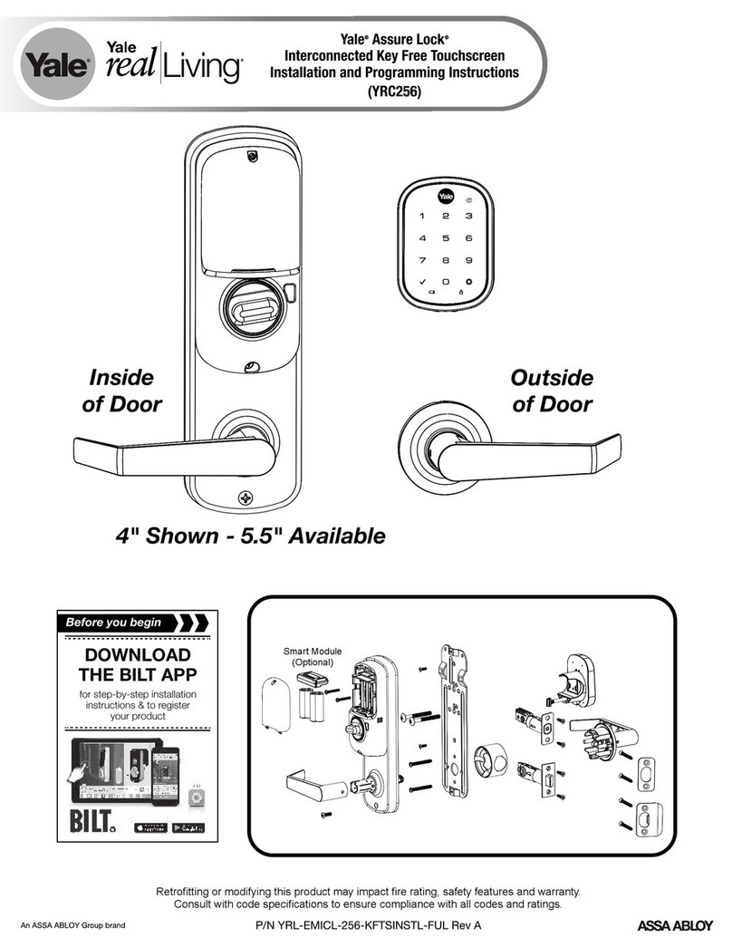
Assa Abloy SARGENT 5300 Series User manual
Assa Abloy
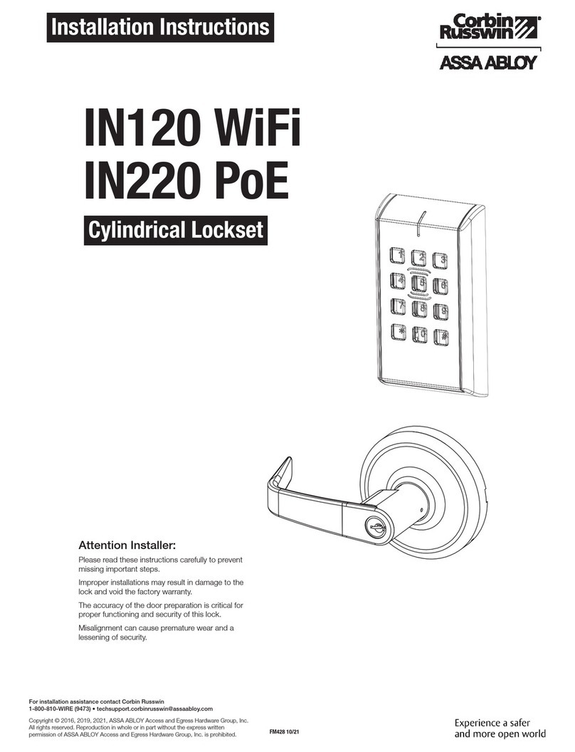
Assa Abloy Yale Assure Lock YRC256-ZW3 Technical specifications
Assa Abloy
Assa Abloy Conrbin Russwin IN120 WiFi User manual
Assa Abloy
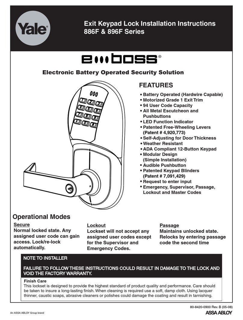
Assa Abloy Yale eBoss 886F Series User manual
Assa Abloy
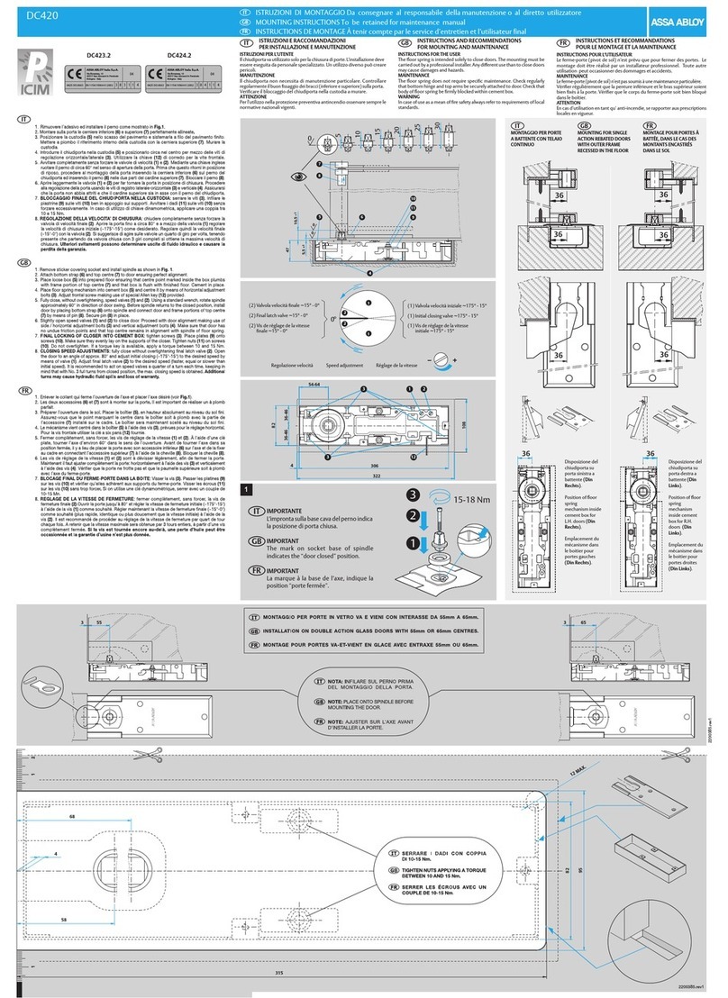
Assa Abloy DC423.2 User manual
Assa Abloy
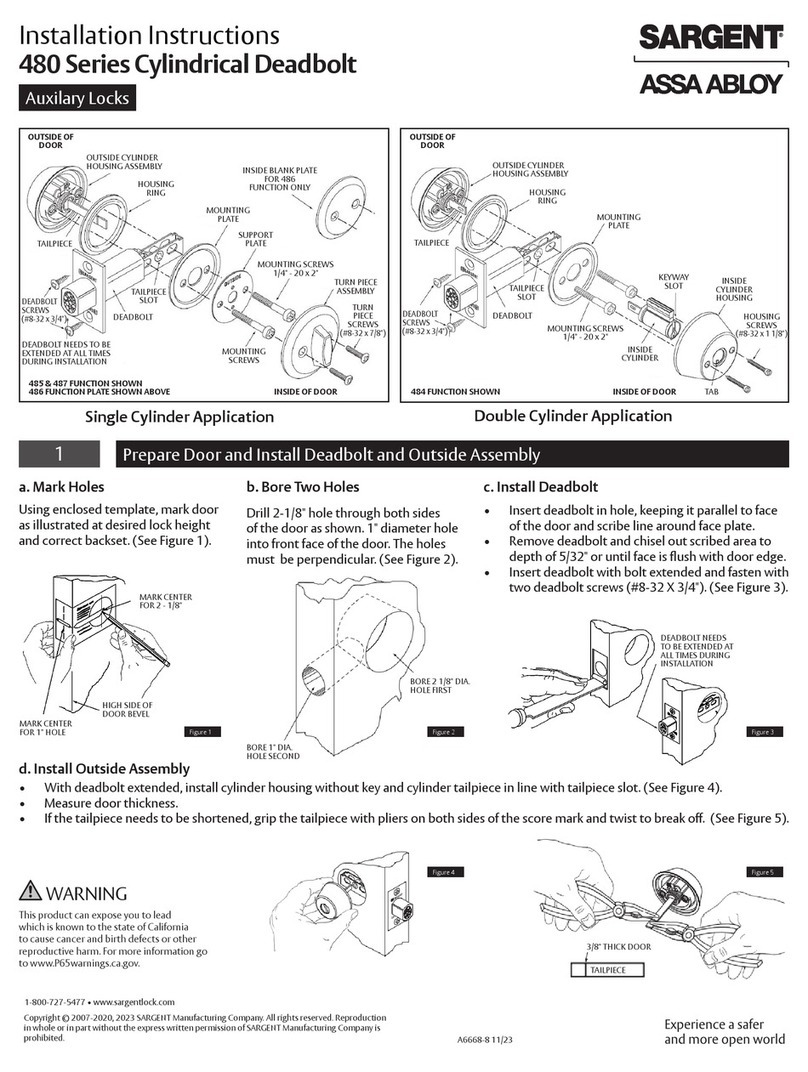
Assa Abloy SARGENT 480 Series User manual
Assa Abloy
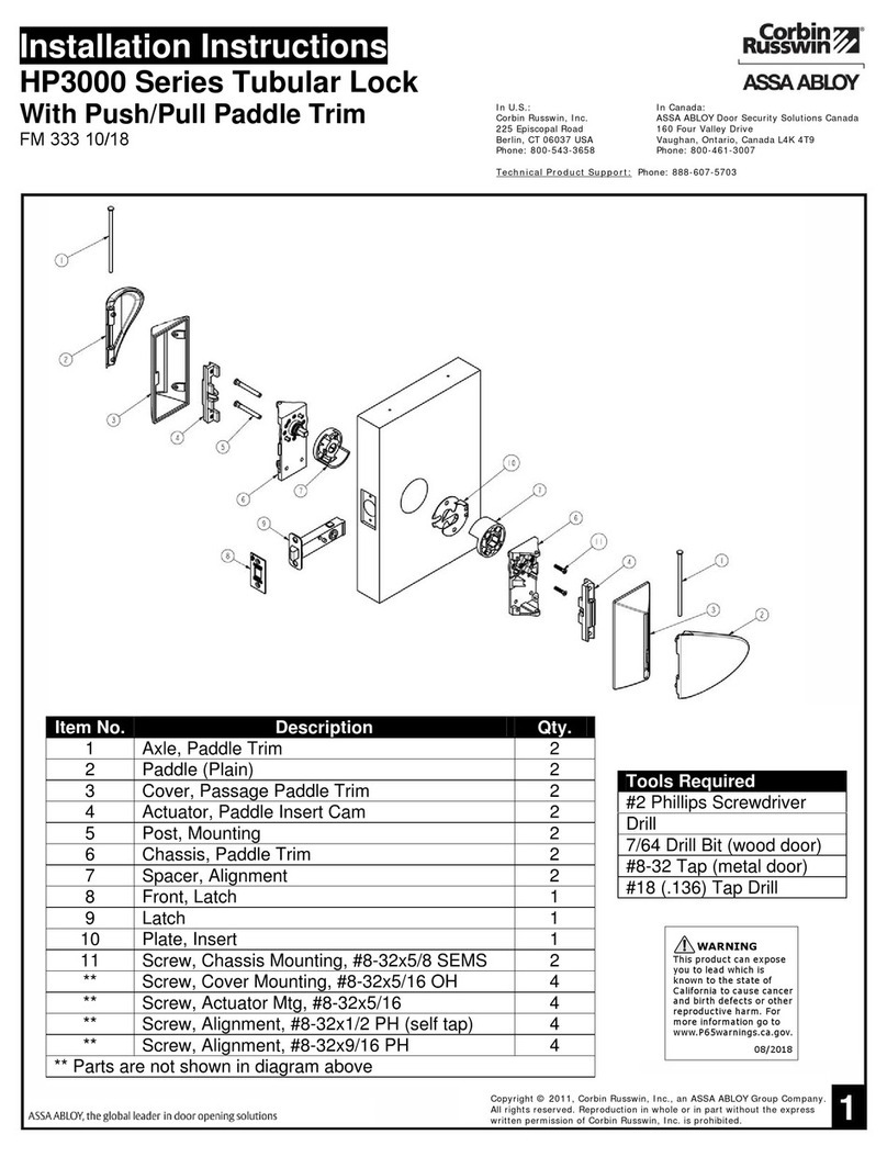
Assa Abloy Corbin Russwin HP3000 Series User manual
Assa Abloy
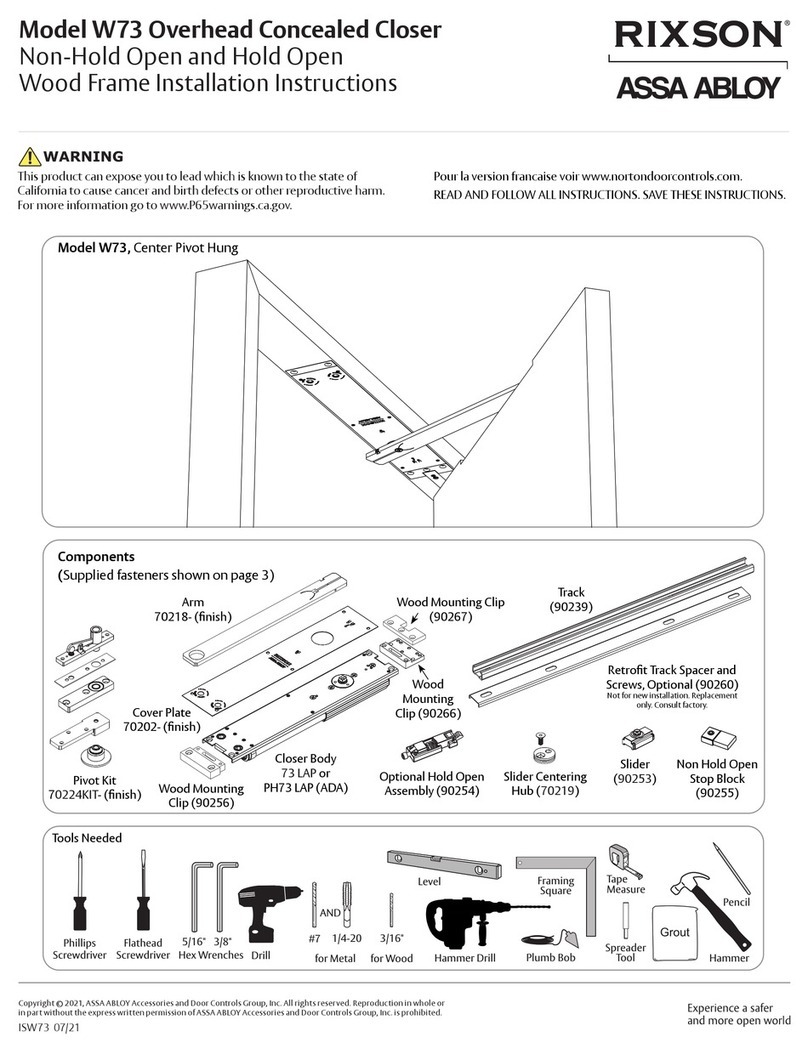
Assa Abloy RIXSON W73 User manual
Assa Abloy
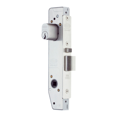
Assa Abloy Lockwood Selector Series User manual
Popular Door Lock manuals by other brands

SCOOP
SCOOP Pullbloc 4.1 FS Panik Assembly instruction

Yale
Yale MORTISE 8800 SERIES installation instructions

Siegenia
Siegenia KFV AS3500 Assembly instructions

Saflok
Saflok Quantum ädesē RFID installation instructions

ArrowVision
ArrowVision Shepherd 210 installation manual
Baldwin
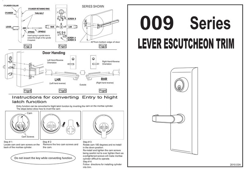
Baldwin 009 Series quick start guide
