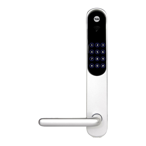
Assa Abloy Corbin Russwin FE5400S Series User manual
Other Assa Abloy Door Lock manuals
Assa Abloy
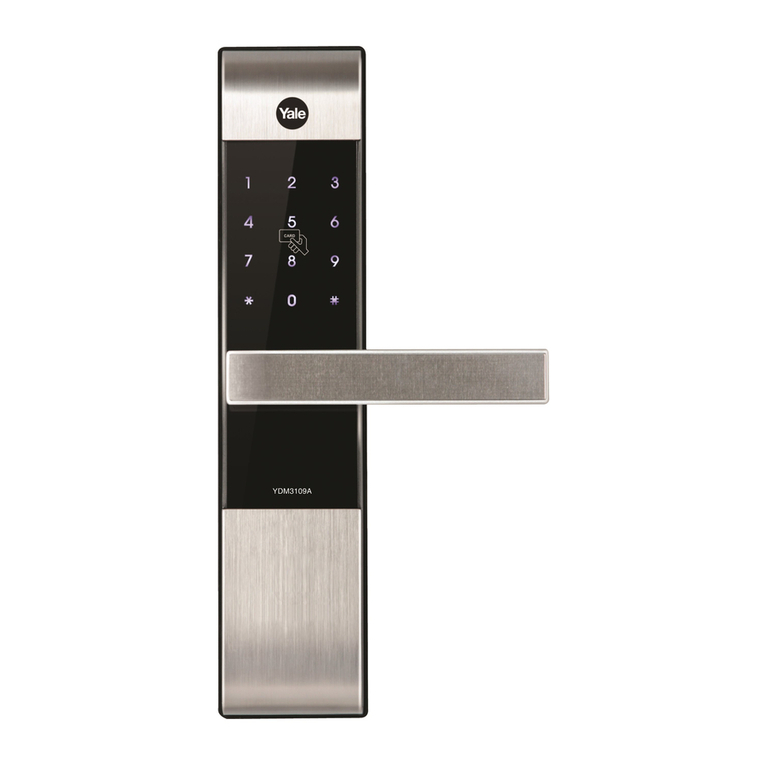
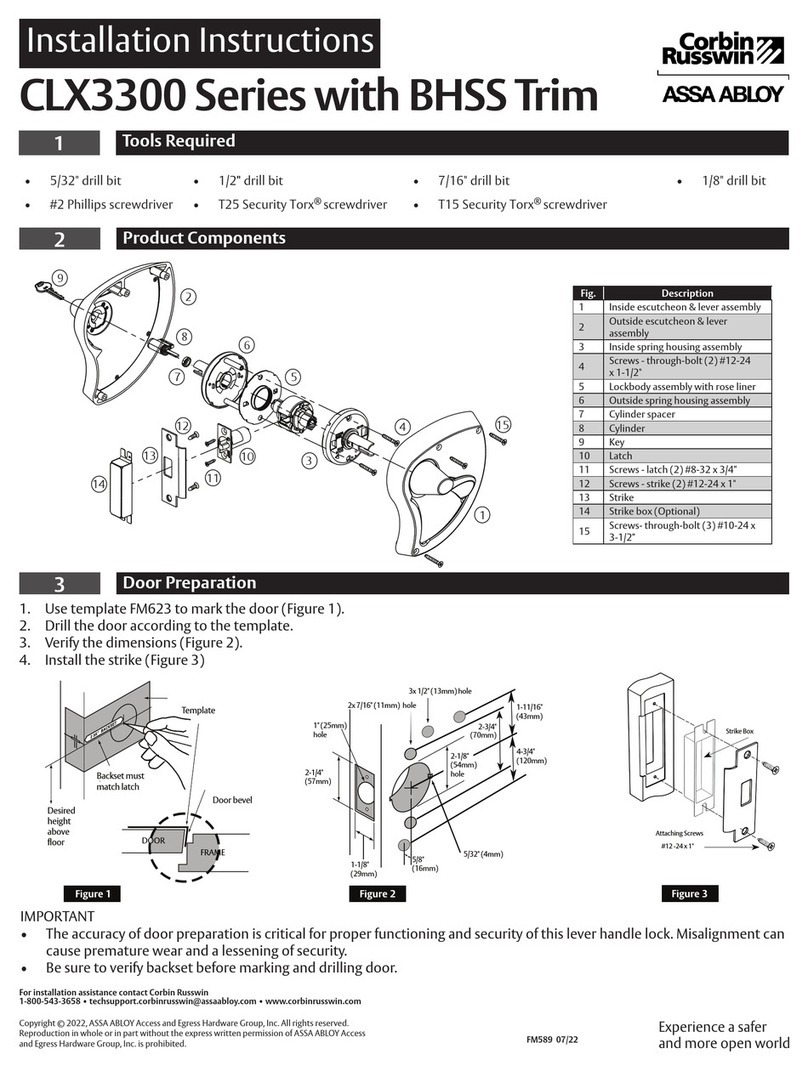
Assa Abloy Yale YDM3109A User manual
Assa Abloy
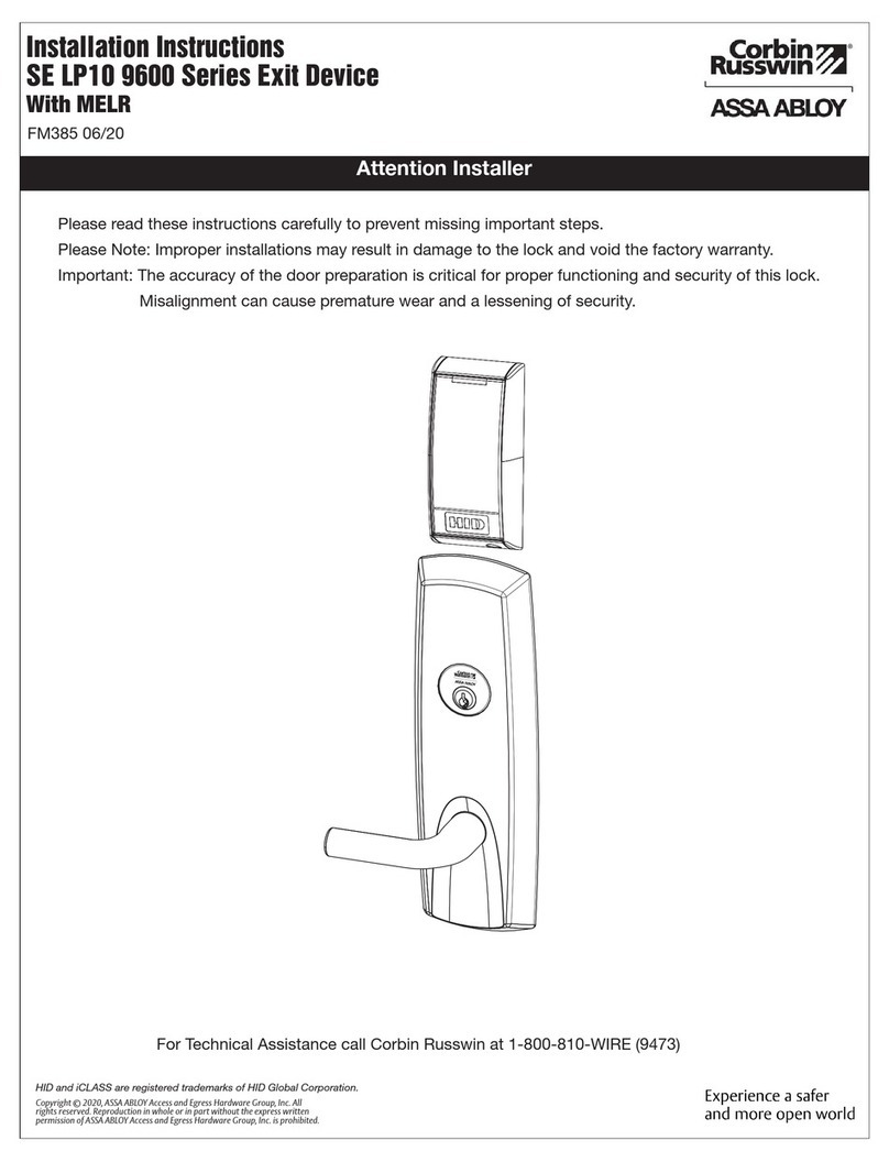
Assa Abloy Corbin Russwin CLX3300 Series User manual
Assa Abloy
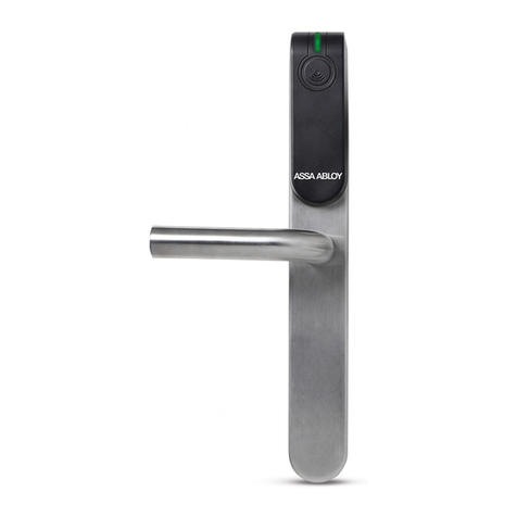
Assa Abloy Corbin Russwin SE LP10 9600 Series User manual
Assa Abloy
Assa Abloy E100 User manual
Assa Abloy
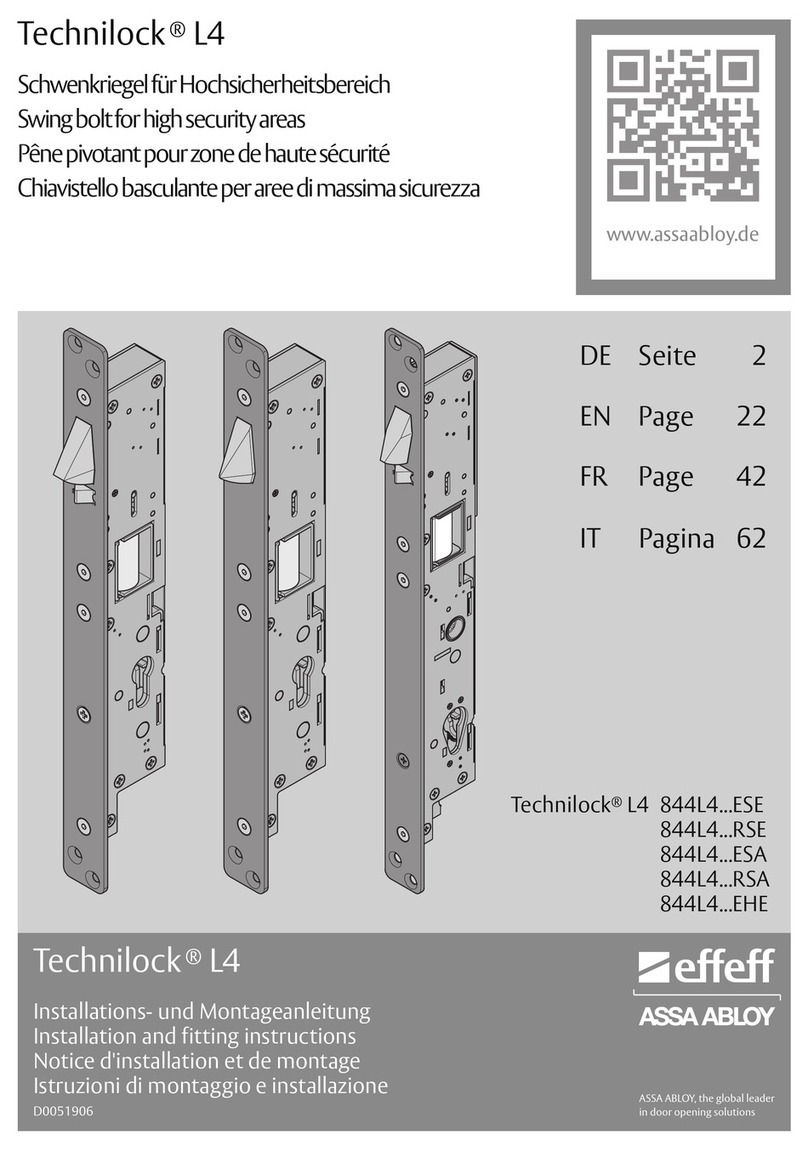
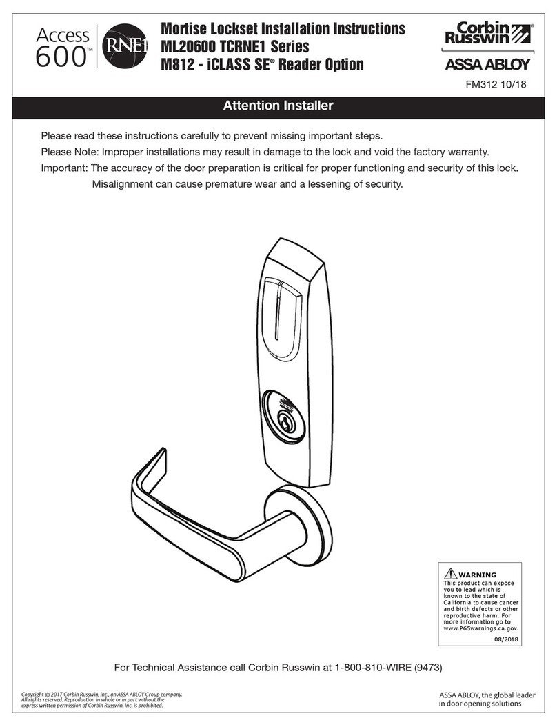
Assa Abloy Effeff Technilock L4 Series User manual
Assa Abloy
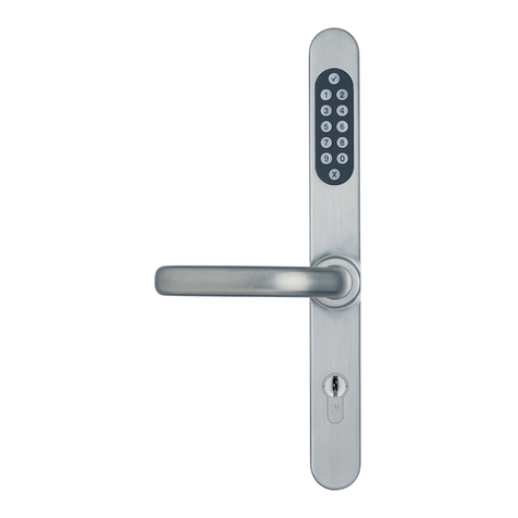
Assa Abloy Corbin Russwin Access 600 CL33600 TCRNE1... User manual
Assa Abloy
Assa Abloy effeff ANYKEY 496 User manual

Assa Abloy
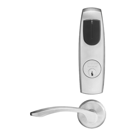
Assa Abloy Lockwood Onyx 9A1A2/5PBLK User manual
Assa Abloy
Assa Abloy Sargent Harmony Series User manual
Assa Abloy
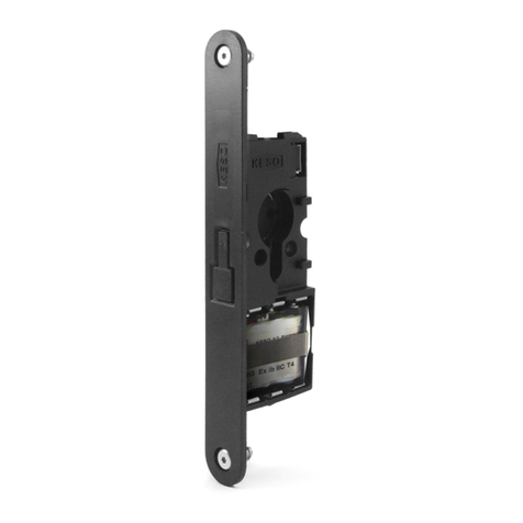
Assa Abloy KESO Genie User manual
Assa Abloy
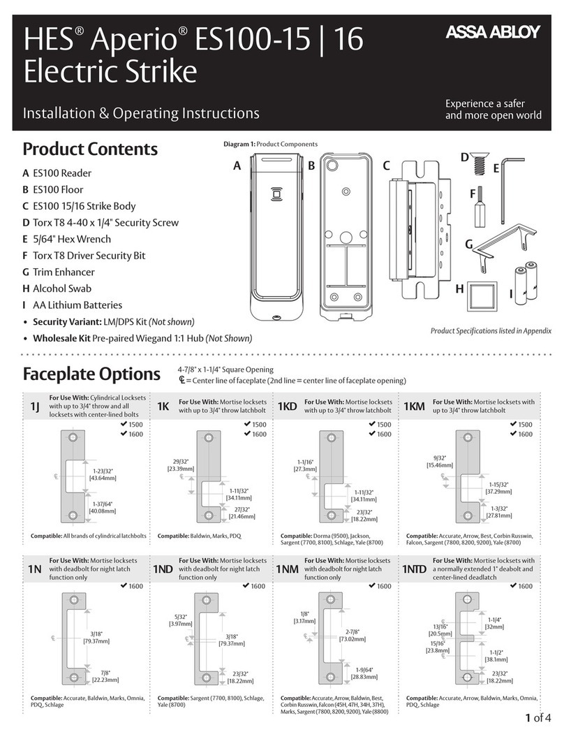
Assa Abloy HES Aperio ES100-15 Manual
Assa Abloy
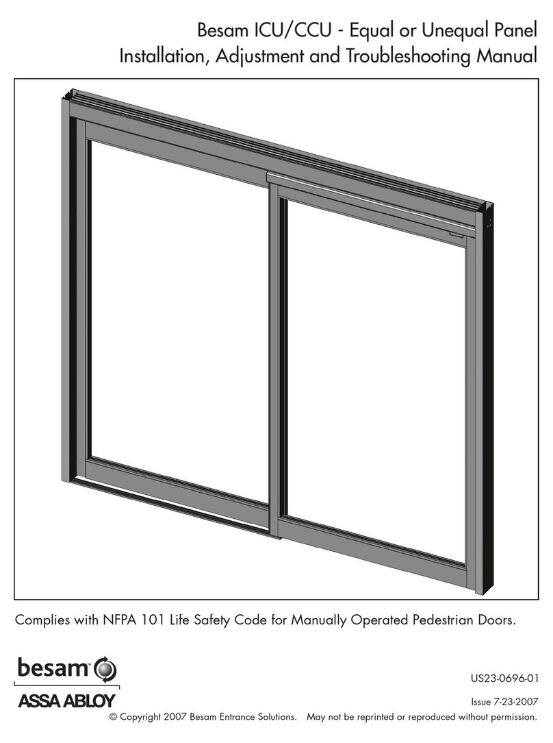
Assa Abloy besam US23-0696-01 Programming manual
Assa Abloy
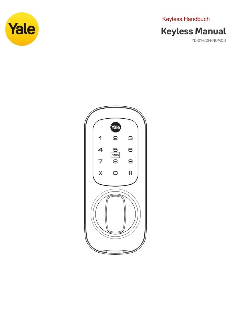
Assa Abloy Yale YD-01-CON-NOMOD User manual

Assa Abloy
Assa Abloy Lockwood 8816 User manual
Assa Abloy
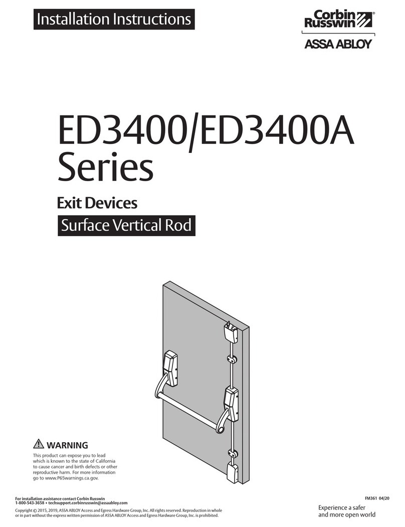
Assa Abloy Corbin Russwin ED3400 Series User manual

Assa Abloy
Assa Abloy Yale Pro SL Technical specifications
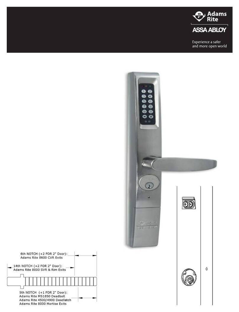
Assa Abloy
Assa Abloy 3090 Mounting instructions
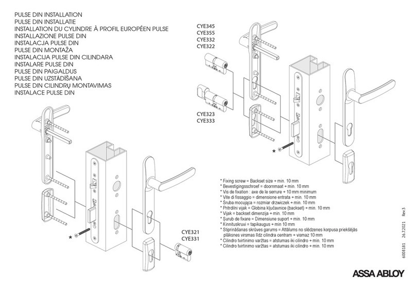
Assa Abloy
Assa Abloy CYE345 User manual
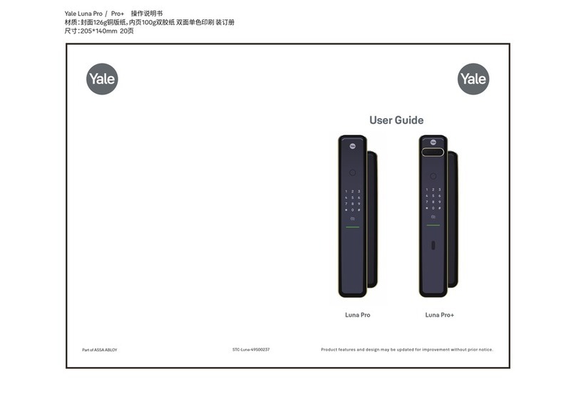
Assa Abloy
Assa Abloy Yale Luna Pro User manual
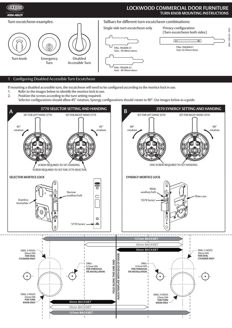
Assa Abloy
Assa Abloy Lockwood 1220 Series User manual
Popular Door Lock manuals by other brands

SCOOP
SCOOP Pullbloc 4.1 FS Panik Assembly instruction

Yale
Yale MORTISE 8800 SERIES installation instructions

Siegenia
Siegenia KFV AS3500 Assembly instructions

Saflok
Saflok Quantum ädesē RFID installation instructions

ArrowVision
ArrowVision Shepherd 210 installation manual
Baldwin
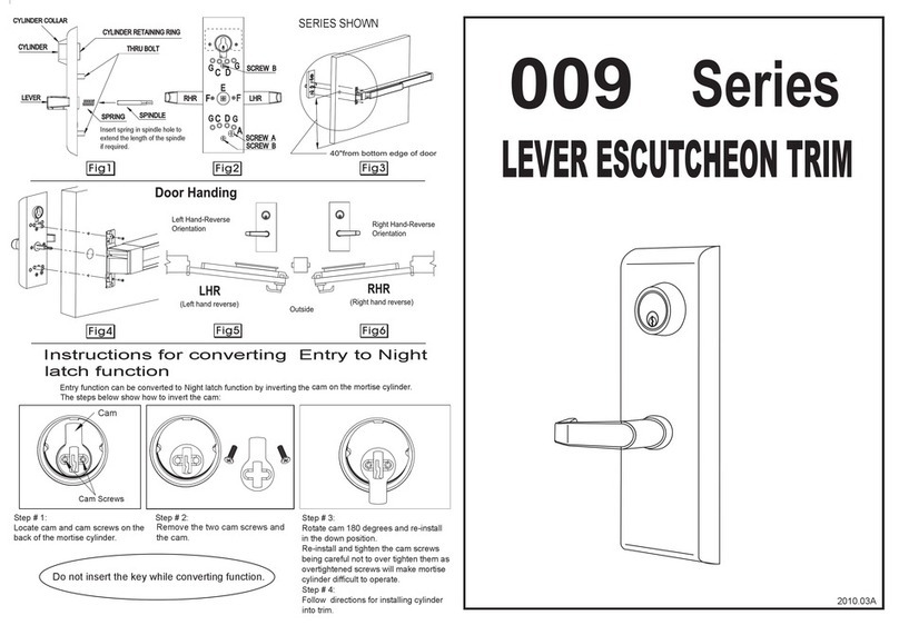
Baldwin 009 Series quick start guide

