Axis AXIS T8310 User manual

ENGLISH
USER’S GUIDE
AXIS T8310 Video Surveillance Control Board
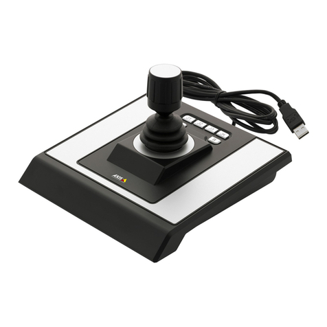
AXIS T8311 Video Surveillance Joystick
AXIS T8312 Video Surveillance Keypad
AXIS T8313 Video Surveillance Jog Dial

Legal Considerations
Video and audio surveillance can be prohibited by laws
that vary from country to country. Check the laws in
your local region before using this product for
surveillance purposes.
Electromagnetic Compatibility (EMC)
This equipment generates, uses and can radiate radio
frequency energy and, if not installed and used in
accordance with the instructions, may cause harmful
interference to radio communications. However, there is
no guarantee that interference will not occur in a
particular installation.
If this equipment does cause harmful interference to
radio or television reception, which can be determined
by turning the equipment off and on, the user is
encouraged to try to correct the interference by one or
more of the following measures: Re-orient or relocate
the receiving antenna. Increase the separation between
the equipment and receiver. Connect the equipment to
an outlet on a different circuit to the receiver. Consult
your dealer or an experienced radio/TV technician for
help. Shielded (STP) network cables must be used with
this unit to ensure compliance with EMC standards.
USA - This equipment has been tested and found to
comply with the limits for a Class B computing device
pursuant to Subpart B of Part 15 of FCC rules, which are
designed to provide reasonable protection against such
interference when operated in a commercial
environment. Operation of this equipment in a
residential area is likely to cause interference, in which
case the user at his/her own expense will be required to
take whatever measures may be required to correct the
interference.
Canada - This Class B digital apparatus complies with
Canadian ICES-003
Europe - This digital equipment fulfills the requirements
for radiated emission according to limit B of EN55022,
and the requirements for immunity according to
EN55024 residential and commercial industry.
Japan - This is a class B product based on the standard
of the Voluntary Control Council for Interference from
Information Technology Equipment (VCCI). If this is used
near a radio or television receiver in a domestic
environment, it may cause radio interference. Install and
use the equipment according to the instruction manual.
Australia - This electronic device meets the
requirements of the Radio communications
(Electromagnetic Compatibility) Standard AS/NZS
CISPR22:2002.
Equipment Modifications
This equipment must be installed and used in strict
accordance with the instructions given in the user
documentation. This equipment contains no
user-serviceable components. Unauthorized equipment
changes or modifications will invalidate all applicable
regulatory certifications and approvals.
Liability
Every care has been taken in the preparation of this
document. Please inform your local Axis office of any
inaccuracies or omissions. Axis Communications AB
cannot be held responsible for any technical or
typographical errors and reserves the right to make
changes to the product and documentation without
prior notice. Axis Communications AB makes no
warranty of any kind with regard to the material
contained within this document, including, but not
limited to, the implied warranties of merchantability
and fitness for a particular purpose. Axis
Communications AB shall not be liable nor responsible
for incidental or consequential damages in connection
with the furnishing, performance or use of this material.
RoHS
This product complies with both the European
RoHS directive, 2002/95/EC, and the Chinese
RoHS regulations, ACPEIP.
WEEE Directive
The European Union has enacted a Directive
2002/96/EC on Waste Electrical and Electronic
Equipment (WEEE Directive). This directive is
applicable in the European Union member
states.
The WEEE marking on this product (see right) or its
documentation indicates that the product must not be
disposed of together with household waste. To prevent
possible harm to human health and/or the environment,
the product must be disposed of in an approved and
environmentally safe recycling process. For further
information on how to dispose of this product correctly,
contact the product supplier, or the local authority
responsible for waste disposal in your area.
Business users should contact the product supplier for
information on how to dispose of this product correctly.
This product should not be mixed with other commercial
waste.
Support
Should you require any technical assistance, please
contact your Axis reseller. If your questions cannot be
answered immediately, your reseller will forward your
queries through the appropriate channels to ensure a
rapid response. If you are connected to the Internet, you
can:
• download user documentation and firmware updates
• find answers to resolved problems in the FAQ database.
Search by product, category, or phrases
• report problems to Axis support by logging in to your
private support area.

AXIS T8310/T8311/T8312/T8313 User’s Guide Page 3
ENGLISH
AXIS T8310, AXIS T8311
AXIS T8312 & AXIS T8313
User’s Guide
This User’s Guide provides instructions for installing AXIS T8310 Video Surveillance Control Board.
For all other aspects of using the product, please see the AXIS Camera Station help pages.
AXIS T8310 Video Surveillance Control Board consists of three units that can be installed separately
or together as one unit. AXIS T8311 gives responsive and accurate control of the pan, tilt and zoom
functionality of the camera(s) on the network. AXIS T8312 is used to navigate quickly between
workspaces, cameras, views and PTZ presets. AXIS T8313 is used to jog and shuttle through
recorded video. All the units are powered through the USB connection.
Installation Steps
1. Check the package contents against the list below.
2. Hardware overview. See page 4.
3. Install the hardware. See page 6
Package Contents
Item Models/variants/notes
Joystick/Keypad/Jog Dial AXIS T8311/AXIS T8312/AXIS T8313
USB cable AXIS T8311: 1 x 200 cm (78.7”) when sold as a separate item,
connects to PC only
AXIS T8312: 1 x 40 cm (15.7”) for connection between units
1 x 200 cm for connection to PC
AXIS T8313: 1 x 40 cm (15.7”)
1 x 80 cm (31.5”)
for connection of two units on either side of keypad
Printed materials AXIS T8310/T8311/T8312/T8313 User’s Guide (this document)
Axis Warranty Document
Important!
This product must be used in
compliance with local laws and
regulations.

Page 4 AXIS T8310/T8311/T8312/T8313 User’s Guide
Hardware Overview
AXIS T8310
Note:
The functionality of the programmable hotkeys is dependent on the application software.
The descriptions below are valid for AXIS Camera Station.
AXIS T8311
AXIS T8311 AXIS T8312 AXIS T8313
Joystick
Go to next in split view
Go to previous
in split view
Preset 3Preset 2Preset 1 Preset 4
USB port

AXIS T8310/T8311/T8312/T8313 User’s Guide Page 5
ENGLISH
AXIS T8312
AXIS T8313
Configuration
Logs
Recordings
Live view
Start Configuration
View
Camera
Preset
Alarm (Tool)
Time
0-9
Alt
Tab
USB port (2x) USB port
Jog wheel
Search recordings
Toggle search/
Snapshot
Play/PausePreviousBookmark Next
Shuttle wheel
USB port

Page 6 AXIS T8310/T8311/T8312/T8313 User’s Guide
Install the hardware
AXIS T8311 Video Surveillance Joystick, AXIS T8312 Video Surveillance Keypad and AXIS T8313
Video Surveillance Jog Dial can be connected separately or together as one unit using AXIS T8312
Video Surveillance Keypad as a USB hub. The units can be placed interchangeably to meet the
requirements and needs of the workstation and the users.
The illustration below gives examples of how to connect the units.
1. Connect the USB plug to a USB port on your computer.
2. Follow the on-screen instructions (if applicable) to install the necessary drivers.
3. The joystick AXIS T8311 will appear in the Game controllers list in the Windows Control Panel
on your computer.
Open Start > Control Panel > Game Controllers.
4. Start the supporting application software e.g. AXIS Camera Station. The joystick/keypad/jog dial
is automatically detected.
Note:
The system must have a supporting application software, e.g. AXIS Camera Station, that can
detect the new hardware. Go to www.axis.com for information on supporting systems.
Keypad
Computer
Joystick or Jog Dial
USB cable (3x)

AXIS T8310/T8311/T8312/T8313 User’s Guide Page 7
ENGLISH
Troubleshooting
If you experience problems during the installation, please do or check the following:
• Restart the supporting application software, e.g. AXIS Camera Station.
• Disconnect the USB plug from the computer, wait 10 seconds and then reconnect.
• Move the USB plug to another available USB port on your computer.
• Verify that the operating system has identified the joystick. Go to Start > Control
Panel > Game Controllers and follow the provided troubleshooting steps.

Page 8 AXIS T8310/T8311/T8312/T8313 User’s Guide
Technical specifications
Item Specification
Models AXIS T8310 Video Surveillance Control Board:
• AXIS T8311 Video Surveillance Joystick
• AXIS T8312 Video Surveillance Keypad
• AXIS T8313 Video Surveillance Jog Dial
Deflection • AXIS T8311: Square delimiter
Pan/Tilt (XY): ±15° with central return spring
Zoom (Z): ±25° with central return spring
Functionality • AXIS T8311: Control of the pan, tilt, zoom functionality of cameras
• AXIS T8312: Quick navigation between workspaces, cameras, views and
PTZ presets
• AXIS T8313: Jog dial navigation through recorded video
Application defined hotkeys • AXIS T8311: 6 application defined hotkeys
• AXIS T8312: 10 application defined hotkeys of which 5 are LED backlit
keys; 0–9, tab, alt
• AXIS T8313: 6 application defined hotkeys
Casing Polycarbonate ABS
Interface USB 1.1/2.0 compliant
AXIS T8312: Integrated USB hub
System requirements Windows 7, Vista, XP, 2000, 2003 Server
USB 2.0 port
AXIS Camera Station or similar supporting application software, see
www.axis.com for information on supporting systems
Power Via USB interface
Operating conditions Indoor 0°C to 60°C (32°F to 140°C)
Storage conditions Indoor -10°C to 60°C (14°F to 140°F)
Approvals EN 55022: Class B
EN 55024
EN 61000-6-2
FCC Part 15 subpart b
Class B ( CISPR 22) C-Tick
VCCI
ICES-003
IP20
Dimensions (HxWxL) • AXIS T8311: 109 x 182 x 181 mm (4.3” x 7.2” x 7.1”)
• AXIS T8312: 35 x 182 x 181 mm (1.4” x 7.2” x 7.1”)
• AXIS T8313: 45 x 182 x 181 mm (1.8” x 7.2” x 7.1”)
Weight • AXIS T8311: 730 g (1.6 lb.)
• AXIS T8312: 630 g (1.4 lb)
• AXIS T8313: 630 g (1.4 lb)

AXIS T8310/T8311/T8312/T8313 Guide d'installation Page 9
FRAN
Ç
AIS
AXIS T8310, AXIS T8311
AXIS T8312 et AXIS T8313
Guide d'utilisation
Ce guide d'utilisation vous explique comment installer le Kit de contrôle de vidéosurveillance
AXIS T8310. Pour toute autre question concernant l'utilisation du produit, reportez-vous aux pages
d'aide d'AXIS Camera Station.
Le Kit de contrôle de vidéosurveillance AXIS T8310 est composée de trois unités pouvant être reliées
à l'ordinateur individuellement ou en un seul bloc. AXIS T8311 permet une commande précise et
rapide des fonctions de vue panoramique, d'inclinaison et de zoom des caméras du réseau.
AXIS T8312 vous aide à naviguer rapidement dans les espaces de travail, les vues et les préréglages
PTZ. AXIS T8313 facilite la relécture avant/arrière dans une vidéo enregistrée. Toutes les unités sont
alimentées par port USB.
Procédure d'installation
1. Vérifiez que l'emballage contient bien tous les éléments
de la liste ci-dessous.
2. Présentation du matériel. Reportez-vous à la page 10.
3. Installation du matériel. Reportez-vous à la page 12.
Contenu de l'emballage
Article Modèles/variantes/remarques
Manette/clavier/molette AXIS T8311/AXIS T8312/AXIS T8313
Câble USB AXIS T8311
:
1x200cmsiachetéséparément,
pour la connexion à l'ordinateur uniquement
AXIS T8312: 1 x 40 cm pour la connexion entre les unités
1 x 200 cm pour la connexion à l'ordinateur
AXIS T8313: 1 x 40 cm
1x80cm
pour la connexion de deux unités au clavier
Documentation imprimée Guide d'utilisation AXIS T8310/T8311/T8312/T8313 (ce document)
Document de garantie d'Axis
Important !
Ce produit doit être utilisé
conformément aux lois et
réglementations locales en

Page 10 AXIS T8310/T8311/T8312/T8313 Guide
Présentation du matériel
AXIS T8310
Remarque :
Les fonctions associées aux raccourcis clavier programmables varient selon le logiciel
utilisé. Les descriptions ci-dessous correspondent au logiciel AXIS Camera Station.
AXIS T8311
AXIS T8311 AXIS T8312 AXIS T8313
Manette
Accéder à la vue suivante en
mode vue fractionnée
Accéder à la vue
précédente
en mode vue
fractionnée
Prédéfini 3Prédéfini 2Prédéfini 1 Prédéfini 4
Port USB

AXIS T8310/T8311/T8312/T8313 Guide d'installation Page 11
FRAN
Ç
AIS
AXIS T8312
AXIS T8313
Configuration
Journaux
Enregistrements
Visualisation
Page de
démarrage Configuration
Visualisation
Caméra
Prédéfini
Alarme (Outil)
Heure
0-9
Alt
Tabulation
Port USB (x2) Port USB
Molette d'avance
Recherche dans les
enregistrements
Alterner recherche/
capture d'images
Lecture/
Pause
Retour
arrière
Signet Avance rapide
Molette de navigation
Port USB

Page 12 AXIS T8310/T8311/T8312/T8313 Guide
Installation du matériel
Vous pouvez brancher la Manette de vidéosurveillance AXIS T8311, le Clavier de vidéosurveillance
AXIS T8312 et la Molette de vidéosurveillance AXIS T8313 individuellement ou en un seul bloc, en
utilisant le Clavier de vidéosurveillance AXIS T8312 en tant que concentrateur USB. Les unités
peuvent être reliées les unes aux autres de manière interchangeable, en fonction des exigences du
poste de travail et des besoins des utilisateurs.
L'illustration ci-dessous montre un exemple de configuration des unités.
1. Branchez le câble USB à un port USB de votre ordinateur.
2. Suivez les instructions affichées à l'écran (le cas échéant) pour installer les pilotes nécessaires.
3. La manette AXIS T8311 sera ajoutée à la liste des contrôleurs de jeu dans le panneau de
configuration Windows.
Cliquez sur Démarrer > Panneau de configuration > Contrôleurs de jeu.
Clavier
Ordinateur
Manette ou molette
Câble USB (x3)

AXIS T8310/T8311/T8312/T8313 Guide d'installation Page 13
FRAN
Ç
AIS
4. Lancez l'application de prise en charge, par exemple AXIS Camera Station. La manette/le
clavier/la molette est détecté(e) automatiquement.
Remarque :
Le système doit disposer d'un logiciel de prise en charge capable de détecter le nouveau
matériel, tel qu'AXIS Camera Station. Pour plus d'informations sur les logiciels de gestion
vidéo, rendez-vous sur www.axis.com.
Dépannage
En cas de problèmes lors de l'installation, suivez les étapes ci-dessous :
• Lancez à nouveau l'application de prise en charge, par exemple AXIS Camera Station.
• Débranchez le câble USB de votre ordinateur, patientez 10 secondes, puis branchez-le à
nouveau.
• Branchez le câble USB à un autre port USB de l'ordinateur.
• Vérifiez si la manette est reconnue par le système d'exploitation. Cliquez sur
Démarrer > Panneau de configuration > Contrôleurs de jeu et suivez les étapes de
dépannage indiquées.

Page 14 AXIS T8310/T8311/T8312/T8313 Guide
Caractéristiques techniques
Article Caractéristique technique
Modèles Kit de contrôle de vidéosurveillance AXIS T8310 :
• Manette de vidéosurveillance AXIS T8311
• Clavier de vidéosurveillance AXIS T8312
• Molette de vidéosurveillance AXIS T8313
Déviation • AXIS T8311 : séparateur carré
Vue panoramique/inclinaison (XY) : ± 15 ° avec ressort de retour central
Zoom (Z) : ± 25 ° avec ressort de retour central
Fonctionnalités • AXIS T8311 : contrôle de la vue panoramique, de l'inclinaison et du zoom des
caméras
• AXIS T8312 : navigation rapide dans les espaces de travail, les caméras, les vues
et les préréglages PTZ
• AXIS T8313 : recherche rapide avant/arrière dans la vidéo enregistrée
Raccourcis clavier
définis par
l'application
• AXIS T8311 : 6 raccourcis clavier définis par l'application
• AXIS T8312 : 10 raccourcis clavier définis par l'application, dont 5 touches
rétro-éclairées par LED ; 0–9, Tabulation, Alt
• AXIS T8313 : 6 raccourcis clavier définis par l'application
Boîtier Polycarbonate/ABS
Interface Compatible USB 1.1/2.0
AXIS T8312 : concentrateur USB intégré
Configuration du
système
Windows 7, Vista, XP, 2000, 2003 Server
Port USB 2.0
AXIS Camera Station ou un logiciel de prise en charge similaire (pour plus
d'informations sur les logiciels de gestion vidéo, rendez-vous sur www.axis.com)
Alimentation Via l'interface USB
Conditions d'utilisation Utilisation en intérieur, 0 °C à 60 °C
Conditions de stockage Utilisation en intérieur, -10 °C à 60 °C
Homologations EN 55022 : classe B
EN 55024
EN 61000-6-2
FCC Partie 15, Sous-partie B
C-Tick (CISPR 22) Classe B
VCCI
ICES-003
IP20
Dimensions (hxlxL) • AXIS T8311 : 109 x 182 x 181 mm
• AXIS T8312 : 35 x 182 x 181 mm
• AXIS T8313 : 45 x 182 x 181 mm
Poids • AXIS T8311 : 730 g
• AXIS T8312 : 630 g
• AXIS T8313 : 630 g

AXIS T8310/T8311/T8312/T8313 Installationshandbuch Seite 15
DEUTSCH
AXIS T8310, AXIS T8311
AXIS T8312 & AXIS T8313
Benutzerhandbuch
Dieses Benutzerhandbuch enthält Anweisungen für die Installation des AXIS T8310
Videoüberwachungs-Steuerungsgeräts. Alle weiteren Hinweise zur Verwendung des Produkts finden
Sie auf den Hilfeseiten zu AXIS Camera Station.
Das AXIS T8310 Videoüberwachungs-Steuerungsgerät umfasst drei Komponenten, die entweder
einzeln oder als Einheit zusammen installiert werden können. Der AXIS T8311 ermöglicht eine
schnell ansprechende und genaue Steuerung der Funktionen zum Neigen, Schwenken und Zoomen
der Kameras im Netzwerk. Das AXIS T8312 dient zur schnellen Navigation in den Arbeitsbereichen,
Kameras, Ansichten und PTZ-Voreinstellungen. Das AXIS T8313 ermöglicht, durch die
aufgezeichneten Videodaten zu scrollen und zu pendeln. Alle Einheiten werden über die USB-
Verbindung betrieben.
Installationsschritte
1. Prüfen Sie, ob alle in der nachfolgenden Liste
aufgeführten Komponenten vorhanden sind.
2. Sehen Sie sich die Hardwareübersicht an. Siehe Seite 16.
3. Installieren Sie die Hardware. SieheSeite 18
Lieferumfang
Komponente Modelle/Varianten/Anmerkungen
Joystick/
Funktionstastenfeld/Jog Dial
AXIS T8311/AXIS T8312/AXIS T8313
USB-Kabel AXIS T8311: 1 x 200 cm, wenn es separat verkauft wird,
nur für die Verbindung mit dem PC
AXIS T8312: 1 x 40 cm zum Verbinden der Einheiten
1 x 200 cm für die Verbindung mit dem PC
AXIS T8313: 1 x 40 cm
1 x 80 cm
zum Verbinden von zwei Einheiten auf beiden Seiten des
Funktionstastenfelds
Gedruckte Dokumente AXIS T8310/T8311/T8312/T8313 Benutzerhandbuch (dieses Dokument)
Axis-Garantieerklärung
Wichtig!
Verwenden Sie dieses Produkt
unter Beachtung der geltenden
rechtlichen Bestimmungen.

Seite 16 AXIS T8310/T8311/T8312/T8313
Hardwareübersicht
AXIS T8310
Hinweis:
Welche Funktionen durch die programmierbaren Funktionstasten ausgeführt werden, hängt
von der jeweiligen Anwendungssoftware ab. Die folgenden Beschreibungen gelten für AXIS
Camera Station.
AXIS T8311
AXIS T8311 AXIS T8312 AXIS T8313
Joystick
Zum nächsten Bild in der
Teilansicht wechseln
Zum vorherigen Bild
in der Teilansicht
wechseln
Voreinstellung 3
Voreinstellung 2Voreinstellung 1 Voreinstellung 4
USB-Anschluss

AXIS T8310/T8311/T8312/T8313 Installationshandbuch Seite 17
DEUTSCH
AXIS T8312
AXIS T8313
Konfiguration
Protokolle
Aufnahmen
Live-Darstellung
Startseite Konfiguration
Ansicht
Kamera
Voreinstellung
Alarm (Tool)
Zeit
0-9
Alt-Taste
Tab-Taste
USB-Anschluss USB-Anschluss
Jog-Rad
Aufzeichnungen suchen
Umschalten
zwischen Suche/
Snapshot
Wiedergabe
/Pause
VorherigesLesezeichen Nächstes
Shuttle-Rad
USB-Anschluss

Seite 18 AXIS T8310/T8311/T8312/T8313
Installieren der Hardware
Der AXIS T8311 Videoüberwachungs-Joystick, das AXIS T8312 Videoüberwachungs-
Funktionstastenfeld und das AXIS T8313 Videoüberwachungs-Jog Dial können entweder einzeln
oder als Einheit, bei der das AXIS T8312 Videoüberwachungs-Funktionstastenfeld als USB-Hub
dient, verbunden werden. Die Einheiten sind auswechselbar, d. h. sie können entsprechend den
Anforderungen der Workstation und der Anwender angeschlossen werden.
Die folgende Abbildung zeigt Beispiele, wie die Einheiten verbunden werden können.
1. Stecken Sie den USB-Stecker in den USB-Anschluss Ihres Computer.
2. Befolgen Sie ggf. die Bildschirmanweisungen zur Installation der erforderlichen Treiber.
3. Der AXIS T8311-Joystick wird in der Windows-Systemsteuerung Ihres Computers in der Liste
Gamecontroller angezeigt.
Wählen Sie Start > Systemsteuerung > Gamecontroller .
Funktionstastenfeld
Computer
Joystick oder Jog Dial
USB-Kabel (3x)

AXIS T8310/T8311/T8312/T8313 Installationshandbuch Seite 19
DEUTSCH
4. Starten Sie die entsprechende Anwendungssoftware, z. B. AXIS Camera Station. Der Joystick
bzw. das Funktionstastenfeld oder Jog Dial werden automatisch erkannt.
Hinweis:
Auf dem Computer muss eine unterstützte Anwendungssoftware, z. B. AXIS Camera
Station, installiert sein, damit die neue Hardware erkannt werden kann. Weitere
Informationen über unterstützte Systeme finden Sie unter „www.axis.com“.
Fehlerbehebung
Falls bei der Installation Probleme auftreten, führen Sie die folgenden Schritte aus:
• Starten Sie die unterstützte Anwendungssoftware, z. B. AXIS Camera Station, erneut.
• Trennen Sie die USB-Verbindung, indem Sie den USB-Stecker aus dem Computer ziehen.
Warten Sie 10 Sekunden und schließen Sie danach den USB-Stecker wieder an.
• Schließen Sie den USB-Stecker an einem anderen USB-Anschluss Ihres Computers an.
• Vergewissern Sie sich, dass das Betriebssystem den Joystick erkannt hat. Wählen Sie
Start > Systemsteuerung > Gamecontroller und befolgen Sie die Schritte zur
Fehlerbehebung.

Seite 20 AXIS T8310/T8311/T8312/T8313
Technische Daten
Komponente Daten
Modelle AXIS T8310 Videoüberwachungs-Steuerungsgerät:
• AXIS T8311 Videoüberwachungs-Joystick
• AXIS T8312 Videoüberwachungs-Funktionstastenfeld
• AXIS T8313 Videoüberwachungs-Jog Dial
Ablenkung • AXIS T8311: Quadrat-Begrenzung
Schwenken/Neigen (XY): ±15° mit zentraler Rückfederung
Zoom (Z): ±25° mit zentraler Rückfederung
Funktionalität • AXIS T8311: Steuerung der PTZ-Funktionen der Kameras
• AXIS T8312: Schnelle Navigation zwischen Arbeitsbereichen, Kameras,
Ansichten und PTZ-Voreinstellungen
• AXIS T8313: Jog Dial durch die aufgezeichneten Videodaten
Anwendungsspezifische
Funktionstasten
• AXIS T8311: 6 anwendungsspezifische Funktionstasten
• AXIS T8312: 10 anwendungsspezifische Funktionstasten, davon 5 LED
Gegenlichttasten; 0-9, Tab-Taste, Alt-Taste
• AXIS T8313: 6 anwendungsspezifische Funktionstasten
Gehäuse Polykarbonat ABS
Schnittstelle USB 1.1/2.0-konform
AXIS T8312: Integrierter USB-Hub
Systemanforderungen Windows 7, Vista, XP, 2000, 2003 Server
USB 2.0-Anschluss
AXIS Camera Station oder eine ähnliche unterstützte Anwendungssoftware.
Informationen über unterstützte Systeme finden Sie unter „www.axis.com“
Betrieb Über USB-Schnittstelle
Betriebsbedingungen Innenbereich 0°C bis 60°C
Lagerbedingungen Innenbereich -10°C bis 60°C
Zulassungen EN 55022: Klasse B
EN 55024
EN 61000-6-2
FCC Abschnitt 15 Teil b
Klasse B ( CISPR 22) C-Tick
VCCI
ICES-003
IP20
Abmessungen (H x B x T) • AXIS T8311: 109 x 182 x 181 mm (4,3” x 7,2” x 7,1”)
• AXIS T8312: 35 x 182 x 181 mm (1,4” x 7,2” x 7,1”)
• AXIS T8313: 45 x 182 x 181 mm (1,8” x 7,2” x 7,1”)
Gewicht • AXIS T8311: 730 g
• AXIS T8312: 630 g
• AXIS T8313: 630 g
Other manuals for AXIS T8310
1
This manual suits for next models
3
Table of contents
Languages:
Other Axis Security System manuals