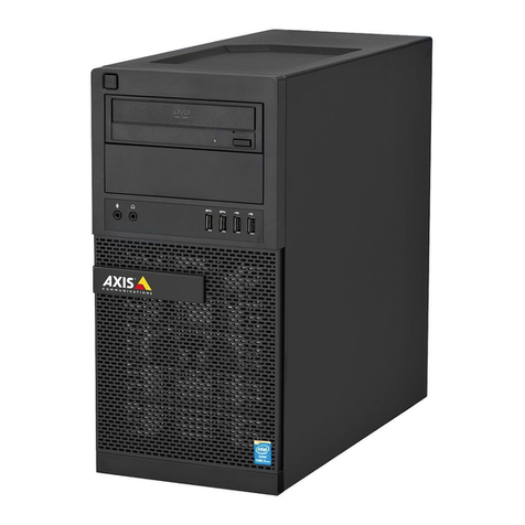
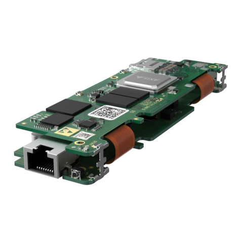
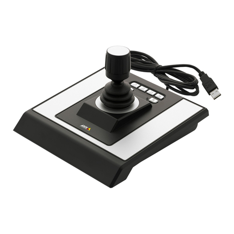
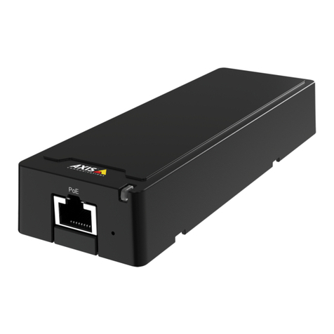
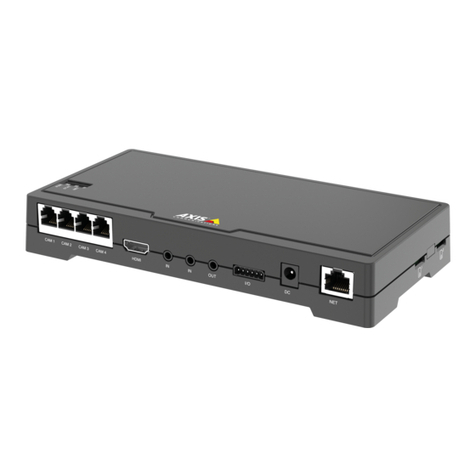
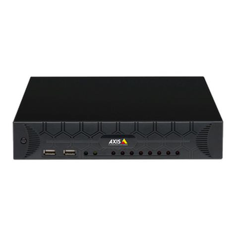
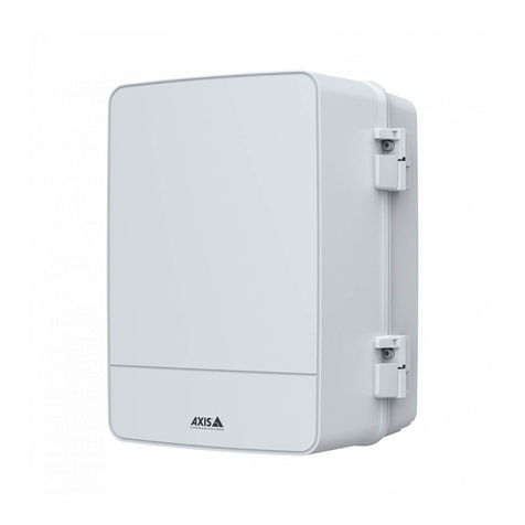
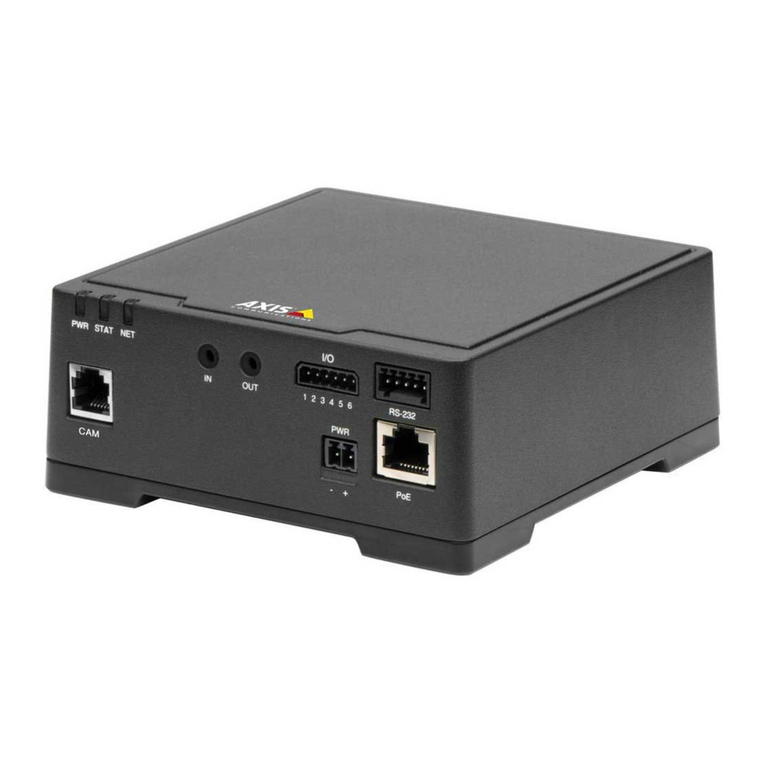
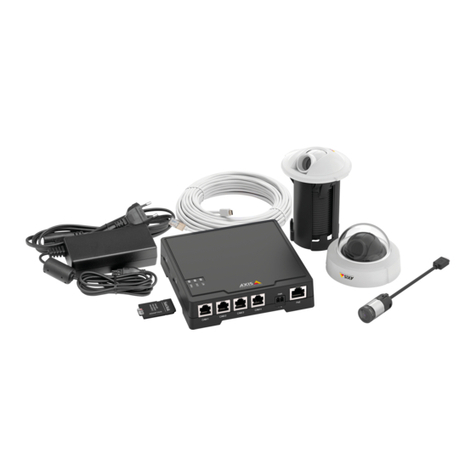
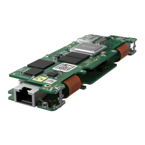
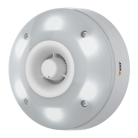
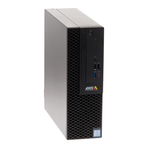
Axis F41 User manual

INSTALLATIONGUIDE
AXISF41MainUnit
InstallationGuide

LegalConsiderations
Videoandaudiosurveillancecanberegulatedby
lawsthatvaryfromcountrytocountry.Checkthe
lawsinyourlocalregionbeforeusingthisproduct
forsurveillancepurposes.
Thisproductincludesone(1)H.24decoderlicense
andone(1)AACdecoderlicense.Topurchasefurther
licenses,contactyourreseller.
Liability
Everycarehasbeentakeninthepreparationofthis
document.PleaseinformyourlocalAxisofceof
anyinaccuraciesoromissions.AxisCommunications
ABcannotbeheldresponsibleforanytechnicalor
typographicalerrorsandreservestherighttomake
changestotheproductandmanualswithoutprior
notice.AxisCommunicationsABmakesnowarranty
ofanykindwithregardtothematerialcontained
withinthisdocument,including,butnotlimitedto,
theimpliedwarrantiesofmerchantabilityandtness
foraparticularpurpose.AxisCommunicationsAB
shallnotbeliablenorresponsibleforincidental
orconsequentialdamagesinconnectionwiththe
furnishing,performanceoruseofthismaterial.This
productisonlytobeusedforitsintendedpurpose.
IntellectalPropertyRights
AxisABhasintellectualpropertyrightsrelatingto
technologyembodiedintheproductdescribedinthis
document.Inparticular,andwithoutlimitation,these
intellectualpropertyrightsmayincludeoneormore
ofthepatentslistedatwww.axis.com/patent.htmand
oneormoreadditionalpatentsorpendingpatent
applicationsintheUSandothercountries.
Thisproductcontainslicensedthird-partysoftware.
Seethemenuitem“About”intheproduct’suser
interfaceformoreinformation.
Thisproductcontainssourcecodecopyright
AppleComputer,Inc.,undertheterms
ofApplePublicSourceLicense2.0(see
www.opensource.apple.com/apsl).Thesourcecodeis
availablefromhttps://developer.apple.com/bonjour/
EqipmentModications
Thisequipmentmustbeinstalledandusedin
strictaccordancewiththeinstructionsgivenin
theuserdocumentation.Thisequipmentcontains
nouser-serviceablecomponents.Unauthorized
equipmentchangesormodicationswillinvalidate
allapplicableregulatorycerticationsandapprovals.
TrademarkAcknowledgments
AXISCOMMUNICATIONS,AXIS,ETRAX,ARTPEC
andVAPIXareregisteredtrademarksortrademark
applicationsofAxisABinvariousjurisdictions.All
othercompanynamesandproductsaretrademarksor
registeredtrademarksoftheirrespectivecompanies.
Apple,Boa,Apache,Bonjour,Ethernet,Internet
Explorer,Linux,Microsoft,Mozilla,Real,SMPTE,
QuickTime,UNIX,Windows,WindowsVistaand
WWWareregisteredtrademarksoftherespective
holders.JavaandallJava-basedtrademarksand
logosaretrademarksorregisteredtrademarksof
Oracleand/oritsafliates.UPnPTMisacertication
markoftheUPnPTMImplementersCorporation.
SD,SDHCandSDXCaretrademarksorregistered
trademarksofSD-3C,LLCintheUnitedStates,
othercountriesorboth.Also,miniSD,microSD,
miniSDHC,microSDHC,microSDXCarealltrademarks
orregisteredtrademarksofSD-3C,LLCintheUnited
States,othercountriesorboth.
ReglatoryInformation
Europe
Thisproductcomplieswiththeapplicable
CEmarkingdirectivesandharmonizedstandards:
•ElectromagneticCompatibility(EMC)
Directive2004/108/EC.SeeElectromagnetic
Compatibility(EMC)2.
•LowVoltage(LVD)Directive200/95/EC.See
afety3.
•RestrictionsofHazardousSubstances(RoHS)
Directive2011/5/EU.SeeDisposaland
Recycling3.
Acopyoftheoriginaldeclarationofconformity
maybeobtainedfromAxisCommunicationsAB.See
ContactInformation3.
ElectromagneticCompatibility(EMC)
Thisequipmenthasbeendesignedandtestedtofulll
applicablestandardsfor:
•Radiofrequencyemissionwheninstalled
accordingtotheinstructionsandusedinits
intendedenvironment.
•Immunitytoelectricalandelectromagnetic
phenomenawheninstalledaccordingto
theinstructionsandusedinitsintended
environment.
USA
Thisequipmenthasbeentestedusingashielded
networkcable(STP)andfoundtocomplywiththe
limitsforaClassBdigitaldevice,pursuanttopart15
oftheFCCRules.Theselimitsaredesignedtoprovide
reasonableprotectionagainstharmfulinterferencein
aresidentialinstallation.Thisequipmentgenerates,
usesandcanradiateradiofrequencyenergyand,
ifnotinstalledandusedinaccordancewiththe
instructions,maycauseharmfulinterferencetoradio
communications.However,thereisnoguaranteethat
interferencewillnotoccurinaparticularinstallation.
Ifthisequipmentdoescauseharmfulinterference
toradioortelevisionreception,whichcanbe
determinedbyturningtheequipmentoffandon,the
userisencouragedtotrytocorrecttheinterference
byoneormoreofthefollowingmeasures:
•Reorientorrelocatethereceivingantenna.
•Increasetheseparationbetweentheequipment
andreceiver.
•Connecttheequipmentintoanoutletona
circuitdifferentfromthattowhichthereceiver
isconnected.

•Consultthedealeroranexperiencedradio/TV
technicianforhelp.
Theproductshallbeconnectedusingashielded
networkcable(STP)thatisproperlygrounded.
Canada
Thisdigitalapparatuscomplieswith
CANICES-3(ClassB).Theproductshallbe
connectedusingashieldednetworkcable(STP)
thatisproperlygrounded.Cetappareilnumérique
estconformeàlanormeCANNMB-3(classeB).Le
produitdoitêtreconnectéàl'aided'uncâbleréseau
blindé(STP)quiestcorrectementmisàlaterre.
Europe
ThisdigitalequipmentfulllstherequirementsforRF
emissionaccordingtotheClassBlimitofEN55022.
Theproductshallbeconnectedusingashielded
networkcable(STP)thatisproperlygrounded.
Thisproductfulllstherequirementsforemission
andimmunityaccordingtoEN50121-4and
IEC223-4railwayapplications.
Thisproductfulllstherequirementsforimmunity
accordingtoEN1000--1residential,commercial
andlight-industrialenvironments.
Thisproductfulllstherequirementsforimmunity
accordingtoEN1000--2industrialenvironments.
Thisproductfulllstherequirementsforimmunity
accordingtoEN55024ofceandcommercial
environments.
Australia/NewZealand
Thisdigitalequipmentfulllstherequirements
forRFemissionaccordingtotheClassBlimitof
AS/NZSCISPR22.Theproductshallbeconnected
usingashieldednetworkcable(STP)thatisproperly
grounded.
Japan
この装置は、クラスB情報技術装置です。こ
の装置は、家庭環境で使⽤することを⽬的
としていますが、この装置がラジオやテレビ
ジョン受信機に近接して使⽤されると、受信
障害を引き起こすことがあります。取扱説明
書に従って正しい取り扱いをして下さい。本
製品は、シールドネットワークケーブル(STP)
を使⽤して接続してください。また適切に
接地してください。
Korea
이기기는가정용(B급)전자파적합기기로서
주로가정에서사용하는것을목적으로하며,
모든지역에서사용할수있습니다.적절히
접지된STP(shieldedtwistedpair)케이블을
사용하여제품을연결하십시오.
Safety
ThisproductcomplieswithIEC/EN/UL0950-1,
SafetyofInformationTechnologyEquipment.Ifits
connectingcablesareroutedoutdoors,theproduct
shallbegroundedeitherthroughashieldednetwork
cable(STP)orotherappropriatemethod.
Thepowersupplyusedwiththisproductshallfulll
therequirementsforSafetyExtraLowVoltage
(SELV)andLimitedPowerSource(LPS)accordingto
IEC/EN/UL238-1orIEC/EN/UL0950-1.
DisposalandRecycling
Whenthisproducthasreachedtheendofits
usefullife,disposeofitaccordingtolocallaws
andregulations.Forinformationaboutyour
nearestdesignatedcollectionpoint,contactyour
localauthorityresponsibleforwastedisposal.In
accordancewithlocallegislation,penaltiesmaybe
applicableforincorrectdisposalofthiswaste.
Europe
Thissymbolmeansthattheproductshall
notbedisposedoftogetherwithhouseholdor
commercialwaste.Directive2012/19/EUonwaste
electricalandelectronicequipment(WEEE)is
applicableintheEuropeanUnionmemberstates.
Topreventpotentialharmtohumanhealthandthe
environment,theproductmustbedisposedofinan
approvedandenvironmentallysaferecyclingprocess.
Forinformationaboutyournearestdesignated
collectionpoint,contactyourlocalauthority
responsibleforwastedisposal.Businessesshould
contacttheproductsupplierforinformationabout
howtodisposeofthisproductcorrectly.
Thisproductcomplieswiththerequirementsof
Directive2011/5/EUontherestrictionoftheuse
ofcertainhazardoussubstancesinelectricaland
electronicequipment(RoHS).
China
Thisproductcomplieswiththerequirements
ofthelegislativeactAdministrationontheControlof
PollutionCausedbyElectronicInformationProducts
(ACPEIP).
ContactInformation
AxisCommunicationsAB
Emdalavägen14
2239Lund
Sweden
Tel:+442721800
Fax:+4413130
www.axis.com
Spport
Shouldyourequireanytechnicalassistance,please
contactyourAxisreseller.Ifyourquestionscannot
beansweredimmediately,yourresellerwillforward
yourqueriesthroughtheappropriatechannelsto
ensurearapidresponse.Ifyouareconnectedtothe
Internet,youcan:
•downloaduserdocumentationandsoftware
updates

•ndanswerstoresolvedproblemsintheFAQ
database.Searchbyproduct,category,or
phrase
•reportproblemstoAxissupportstaffbylogging
intoyourprivatesupportarea
•chatwithAxissupportstaff
•visitAxisSupportatwww.axis.com/techsup/
LearnMore!
VisitAxislearningcenterwww.axis.com/academy/for
usefultrainings,webinars,tutorialsandguides.

AXISF41MainUnit
SafetyInformation
ReadthroughthisInstallationGuidecarefullybeforeinstallingtheproduct.
KeeptheInstallationGuideforfuturereference.
HazardLevels
DANGER
Indicatesahazardoussituationwhich,ifnotavoided,willresult
indeathorseriousinjury.
WARNING
Indicatesahazardoussituationwhich,ifnotavoided,couldresult
indeathorseriousinjury.
CAUTION
Indicatesahazardoussituationwhich,ifnotavoided,couldresult
inminorormoderateinjury.
NO NO
NOTICE TICE
TICE
Indicatesasituationwhich,ifnotavoided,couldresultindamage
toproperty.
OtherMessageLevels
Important
Indicatessignicantinformationwhichisessentialforthe
producttofunctioncorrectly.
Note
Indicatesusefulinformationwhichhelpsingettingthemostout
oftheproduct.
5

AXISF41MainUnit
SafetyInstructions
NO NO
NOTICE TICE
TICE
•TheAxisproductshallbeusedincompliancewithlocallaws
andregulations.
•TousetheAxisproductoutdoors,orinsimilarenvironments,it
shallbeinstalledinanapprovedoutdoorhousing.
•StoretheAxisproductinadryandventilatedenvironment.
•AvoidexposingtheAxisproducttoshocksorheavypressure.
•Donotinstalltheproductonunstablebrackets,surfacesor
walls.
•UseonlyapplicabletoolswheninstallingtheAxisproduct.
Usingexcessiveforcewithpowertoolscouldcausedamage
totheproduct.
•Donotusechemicals,causticagents,oraerosolcleaners.
•Useacleanclothdampenedwithpurewaterforcleaning.
•Useonlyaccessoriesthatcomplywiththetechnicalspecication
oftheproduct.ThesecanbeprovidedbyAxisorathirdparty.
•UseonlysparepartsprovidedbyorrecommendedbyAxis.
•Donotattempttorepairtheproductyourself.ContactAxis
supportoryourAxisresellerforservicematters.
•Thepowersupplyshallbepluggedintoasocketoutletinstalled
neartheproductandshallbeeasilyaccessible.
•Usealimitedpowersource(LPS)witheitheraratedoutput
powerlimitedto≤100Woraratedoutputcurrentlimitedto
≤5A.
6

AXISF41MainUnit
Transportation
NO NO
NOTICE TICE
TICE
•WhentransportingtheAxisproduct,usetheoriginalpackaging
orequivalenttopreventdamagetotheproduct.
Battery
TheAxisproductusesa3.0VBR2032lithiumbatteryasthepowersupply
foritsinternalreal-timeclock(RTC).Undernormalconditionsthisbattery
willlastforaminimumofveyears.
LowbatterypoweraffectstheoperationoftheRTC,causingittoresetat
everypower-up.Whenthebatteryneedsreplacing,alogmessagewill
appearintheproduct’sserverreport.Formoreinformationaboutthe
serverreport,seetheproduct´ssetuppagesorcontactAxissupport.
Thebatteryshouldnotbereplacedunlessrequired,butifthebattery
doesneedreplacing,contactAxissupportatwww.axis.com/techsupfor
assistance.
Lithiumcoincell3.0Vbatteriescontain1,2-dimethoxyethane;ethylene
glycoldimethylether(EGDME),CASno.110-71-4.
WARNING
•Riskofexplosionifthebatteryisincorrectlyreplaced.
•Replaceonlywithanidenticalbatteryorabatterywhichis
recommendedbyAxis.
•Disposeofusedbatteriesaccordingtolocalregulationsorthe
batterymanufacturer'sinstructions.
7

8

AXISF41MainUnit
InstallationGuide
ThisInstallationGuideprovidesinstructionsforinstallingAXISF41Main
Unitonyournetwork.Forotheraspectsofusingtheproduct,seetheUser
Manualavailableatwww.axis.com
InstallationSteps
1.Makesurethepackagecontents,toolsandothermaterials
necessaryfortheinstallationareinorder.Seepage9.
2.Studythehardwareoverview.Seepage10.
3.Studythespecications.Seepage14.
4.Installthehardware.Seepage19.
5.Accesstheproduct.Seepage21.
PackageContents
•AXISF41MainUnit
•2–pinpowerconnectorblock
•–pinI/Oconnectorblock
•5–pinRS232connectorblock
•Printedmaterials
-InstallationGuide(thisdocument)
-Extraserialnumberlabel(2x)
-AVHSAuthenticationkey
RecommendedTools
•TorxscrewdriverT20toremovetheplasticcoverbottom
OptionalAccessories
•AXISF8001SurfaceMountwithStrainRelief
•AXISF8002DINRailClip
9

AXISF41MainUnit
Forinformationaboutavailableaccessories,seewww.axis.com
HardwareOverview
1.Controlbutton
2.Dcardslot
3.LEDs(Power,tatus,Network)
4.RJ12connector
5.Audioin
6.Audioout
7.I/Oconnector
8.Powerconnector
9.Networkconnector(PoE)
10.R232connector
11.Plasticbottomplate
10

AXISF41MainUnit
LEDIndicators
Note
•TheStatusLEDcanbeconguredtobeunlitduringnormal
operation.Tocongure,gotoSetupSystemOptionsPorts
&DevicesLED.Seetheonlinehelpformoreinformation.
•TheStatusLEDcanbeconguredtoashwhileaneventis
active.
•TheStatusLEDcanbeconguredtoashforidentifyingthe
unit.GotoSetupSystemOptionsMaintenance.
StatusLEDIndication
GreenSteadygreenfornormaloperation.
AmberSteadyduringstartup.Flashes
whenrestoringsettings.
RedFlashesredforrmwareupgrade
failure.
NetworkLEDIndication
GreenSteadyforconnectiontoa100
Mbit/snetwork.Flashesfor
networkactivity.
AmberSteadyforconnectiontoa10
Mbit/snetwork.Flashesfor
networkactivity.
UnlitNonetworkconnection.
11

AXISF41MainUnit
PowerLEDIndication
GreenNormaloperation.
AmberFlashesgreen/amberduring
rmwareupgrade.
ConnectorsandBttons
Forspecicationsandoperatingconditions,seepage14.
NetworkConnector
RJ45EthernetconnectorwithPoweroverEthernet(PoE).
NO NO
NOTICE TICE
TICE
Theproductshallbeconnectedusingashieldednetworkcable
(STP).Allcablesconnectingtheproducttothenetworkshall
beintendedfortheirspecicuse.Makesurethatthenetwork
devicesareinstalledinaccordancewiththemanufacturer’s
instructions.Forinformationaboutregulatoryrequirements,see
ElectromagneticCompatibility(EMC)2.
I/OConnector
Usewithexternaldevicesincombinationwith,forexample,tampering
alarms,motiondetection,eventtriggering,timelapserecordingandalarm
notications.Inadditiontothe0VDCreferencepointandpower(DC
output),theI/Oconnectorprovidestheinterfaceto:
•Digitaloutput–Forconnectingexternaldevicessuchasrelays
andLEDs.ConnecteddevicescanbeactivatedbytheVAPIX®
ApplicationProgrammingInterface,outputbuttonsonthe
LiveViewpageorbyanActionRule.Theoutputwillshowas
active(shownunderSystemOptionsPorts&Devices)if
thealarmdeviceisactivated.
•Digitalinput–Analarminputforconnectingdevicesthat
cantogglebetweenanopenandclosedcircuit,forexample:
PIRs,door/windowcontacts,glassbreakdetectors,etc.When
12

AXISF41MainUnit
asignalisreceivedthestatechangesandtheinputbecomes
active(shownunderSystemOptionsPorts&Devices).
PowerConnector
2-pinterminalblockforpowerinput.UseaSafetyExtraLowVoltage
(SELV)compliantlimitedpowersource(LPS)witheitheraratedoutput
powerlimitedto≤100Woraratedoutputcurrentlimitedto≤5A.
AdioConnector
TheAxisproducthasthefollowingaudioconnectors:
•Audioin–3.5mminputforamonomicrophone,oraline-in
monosignal(leftchannelisusedfromastereosignal).
•Audioout–3.5mmoutputforaudio(linelevel)thatcanbe
connectedtoapublicaddress(PA)systemoranactivespeaker
withabuilt-inamplier.Astereoconnectormustbeused
foraudioout.
RS232Connector
5-pinterminalblockfortheRS232serialinterfaceusedtocontrolauxiliary
equipment.InordertousetheRS232port,athirdpartyapplicationfor
AXISCameraApplicationPlatformisrequired.
RJ12Connector
TheRJ12connectorisusedforconnectingthesensorunittothemainunit.
Forinformationonhowtoshortenthesensorunitcableseehorten
ensorUnitCable.
SDcardslot
NO NO
NOTICE TICE
TICE
•RiskofdamagetoSDcard.Donotusesharptools,metalobjects
orexcessiveforcewheninsertingorremovingtheSDcard.Use
yourngerstoinsertandremovethecard.
13

AXISF41MainUnit
•Riskofdatalossandcorruptedrecordings.Donotremovethe
SDcardwhiletheproductisrunning.Disconnectpoweror
unmounttheSDcardfromtheAxisproduct’swebpagesbefore
removal.
ThisproductsupportsSD/SDHC/SDXCcards(notincluded).
ForSDcardrecommendations,seewww.axis.com
ControlBtton
Forlocationofthecontrolbutton,seeHardwareOverviewonpage10.
Thecontrolbuttonisusedfor:
•Resettingtheproducttofactorydefaultsettings.Seepage22.
•ConnectingtoanAXISVideoHostingSystemserviceorAXIS
InternetDynamicDNSService.Formoreinformationabout
theseservices,seetheUserManual.
Specications
TheAxisproductisintendedforindooruse.
ProductClassica-
tionTemperatureHumidity
AXISF41IEC/EN05
29-30°Cto0°C
(-22°Fto
140°F)
10-85%RH
(non-condensing)
14

AXISF41MainUnit
Connectors
I/OConnector
–pinterminalblock
Foranexamplediagram,seeConnectionDiagramsonpage18.
Func-
tionP-
i-
n
NotesSpecications
0VDC(-)10VDC
DC
output2Canbeusedtopowerauxiliary
equipment.
Note:Thispincanonlybeused
aspowerout.
12VDC
Maxload=50mA
Digitalinput–Connecttopin
1toactivate,orleaveoating
(unconnected)todeactivate.
0tomax30VDC Cong-
urable
(Inputor
Output)
3
–
Digitaloutput–Connected
topin1whenactivated,
oating(unconnected)when
deactivated.Ifusedwithan
inductiveload,e.g.arelay,
adiodemustbeconnected
inparallelwiththeload,for
protectionagainstvoltage
transients.
0tomax30VDC,
opendrain,
100mA
15

AXISF41MainUnit
PowerConnector
2-pinterminalblockforDCpowerinput.Usea
SafetyExtraLowVoltage(SELV)compliantlimited
powersource(LPS)witheitheraratedoutputpower
limitedto≤100Woraratedoutputcurrentlimited
to≤5A.
AdioConnector
3.5mmaudio
connectors
(stereo)
1Tip2Ring3
Sleeve
Audio
InputMicrophone/Linein
Balanced:‘Hot’signal
Microphone/Linein
Unbalanced:
Microphone/Linein
Balanced:
‘Cold’signal
Microphone/Linein
Unbalanced:Unused
Ground
Audio
OutputLineout(mono)Ground
16

AXISF41MainUnit
RS232Connector
5-pinterminalblockfortheRS232serialinterfaceusedtocontrolauxiliary
equipment.Theportcanbeusedinthefollowingmodes:
•2TX/2RXRS-232interface(TXD,RTS,GND,CTS,RXD)
FunctionPinNotes
RS232TDalt1
RS232RTSalt2
RS-232DriverOutput
RS232GND3Ground
RS232CTSalt4
RS232RDalt5
RS-232ReceiverInput
17

AXISF41MainUnit
ConnectionDiagrams
I/OConnector
1
2
3
A
B
D
S
G
10VDC(-)
2DCoutput12V,max50mA
3Example:pushbutton
AI/Oconguredasinput
BI/Oconguredasoutput
18

AXISF41MainUnit
InstalltheHardware
TheAxisF41/F44MainUnitcanbeplacedonatabledesktopormounted
onaDINrail.Tofacilitateroutingthecablesfromthetoporsideremove
the4screws(TorxT20)andsuitablyrealignthebottomplateunderthe
unit(seeHardwareOverviewonpage10).Seewww.axis.comforoptional
accessories.
1.Ifrequired,presstoreleasethedummySDcardandinsertan
SDmemorycardintheSDmemorycardslot.
2.Attachthenetworkcabletoconnecttheunittothenetwork.
3.ConnectthesensorunittothemainunitwiththeRJ12cable.
4.Ifrequired,connectanAC/DCpowersupplytothepower
connector.
5.Ifrequired,attachtheI/Ocableusingthe–pinI/Oconnector
blocktoconnectexternalinput/outputdevices.
.Ifrequired,attachtheaudiocablestoconnectanactive
speaker/externalmicrophone.
19

AXISF41MainUnit
7.Ifrequired,attachtheRS232cabletoconnecttoauxiliary
equipment.
ShortenSensorUnitCable
Thesensorunitisdeliveredwithacable.Notethatthiscablecannotbe
extended.Toshortenthecablefollowthesesteps:
1.Cutthecabletothedesiredlength.Measurefromthesensor
unit.
2.Striptheplasticoutercoatingfromtheendofthecable.
3.Peelbacktheshield.
4.Flattenthecoloredwiresintheorderdescribedbelow.
1Brown
2White/brown
3Notused
4Notused
5White/blue
Blue
NO NO
NOTICE TICE
TICE
Makesurethatthewiresstayinthecorrectorderandthatthe
cableshieldmakesgoodcontactwiththeconnectorshield.
5.InsertthewiresallthewayintoashieldedPCRJ12
connector.
.Useacrimpingtooltofastentheconnectortothecable.
20
Other manuals for F41
2
This manual suits for next models
1
Table of contents
Languages:
Other Axis Security System manuals
Popular Security System manuals by other brands

Xylem
Xylem rule 2004307 instruction manual

DIGITIZE
DIGITIZE System 3505 Installation and operation manual

Nortek
Nortek 2GIG GC3 user guide

Aquavx
Aquavx Scout user manual

10-8 Video Digital Evidence Solutions
10-8 Video Digital Evidence Solutions 10-8 Body Camera user manual

Pima
Pima HUNTER-PRO RXN-9 user guide