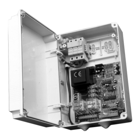
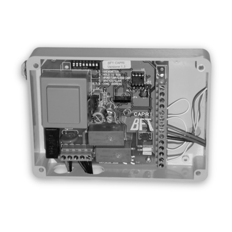
BFT COMPASS 485 User manual

Via Lago di Vico, 44
36015 Schio (VI)
Tel.naz. 0445 696511
Tel.int. +39 0445 696533
Fax 0445 696522
Internet: www.bft.it
E-mail: [email protected]
ISTRUZIONI D’USO E DI INSTALLAZIONE
INSTALLATION AND USER’S MANUAL
INSTRUCTIONS D’UTILISATION ET D’INSTALLATION
MONTAGE- und BEDIENUNGSANLEITUNG
INSTRUCCIONES DE USO Y DE INSTALACION
INSTRUÇÕES DE USO E DE INSTALAÇÃO
D811320 ver.04 30-11-05
ISCHEDA CONTROLLO TRANSPONDER
TRANSPONDER CONTROL CARD
CARTE DE CONTROLE TRANSPONDEUR
TRANSPONDER - STEUERUNG
PLACA DE CONTROL TRANSPONDER
PLACA DE CONTROLO TRANSPONDER
GB
F
D
E
P
COMPASS-485/232

2 - COMPASS-485/232 - Ver. 04
D811320_04

MANUALE D’USO ITALIANO
Nel ringraziarVi per la preferenza accordata a questo prodotto, la
ditta è certa che da esso otterrete le prestazioni necessarie al Vostro
uso. Leggete attentamente l’opuscolo “Avvertenze” ed il “Libretto
istruzioni” che accompagnano questo prodotto in quanto forniscono
importanti indicazioni riguardanti la sicurezza, l’installazione, l’uso e la
manutenzione. Questo prodotto risponde alle norme riconosciute della
tecnica e della disposizioni relative alla sicurezza. Confermiamo che è
conforme alle seguenti direttive europee: 89/336/CEE, 73/23/CEE (e
loro modifiche successive).
1) GENERALITÀ
COMPASS-485 è una scheda di controllo transponder da abbinare al
lettore di prossimità COMPASS-READER. È indicato per una gestione
degli accessi interni ed esterni di edifici pubblici e privati, alberghi,
collettività, ecc.
Il sistema può essere interfacciato tramite COMPASS-232 ad un PC
provvisto del software SECURBASE per il completo monitoraggio
degli accessi.
Per la sua tipologia costruttiva l’utilizzo di COMPASS-485/COMPASS-
READER è indicato sia per il controllo di accessi interni sia per il controllo
di accessi dall’esterno degli edifici.
Accessori:
COMPASS-ISOCARD:
Tessera di prossimità standard ISO, con possibilità di personalizzazione
(foto, dati anagrafici, ecc.)
COMPASS-RING:
Portachiavi con transponder, dotato delle stesse funzionalità della
tessera.
MITTO2-T/MITTO4-T:
Trasmettitore rolling-code con transponder, dotato delle stesse funzio-
nalità della tessera.
Le principali caratteristiche del sistema COMPASS-485/COMPASS-
READER:
• Accesso a tessera di prossimità
• I parametri di sistema e la mappa codici sono memorizzati in una
memoria non volatile, che può conservare i dati inseriti per anni
anche in assenza di alimentazione elettrica.
• La memoria può gestire fino a 6000 tessere.
• Il tempo di apertura porta può essere liberamente impostato da 1
a 25 secondi.
• Il tempo di controllo porta aperta può essere liberamente impostato
da 1 a 250 secondi.
• Ingresso per pulsante di apertura porta e ingresso stato del varco
(aperto/chiuso)
• Contenitore in ABS con membrana multistrato resistente all’uso ed
agli agenti atmosferici.
2) ACCESSO
Avvicinate la tessera di prossimità alla membrana del COMPASS-REA-
DER in posizione parallela e ad una distanza di circa 5-10 cm (Fig.1).
• Se il LED DOOR lampeggia giallo commuta a verde e viene emesso
un segnale acustico, la tessera risulta riconosciuta e abilitata e viene
attivata l’apertura.
• Se il LED DOOR resta giallo e viene emesso un segnale acustico,
la tessera risulta riconosciuta ma non abilitata e non viene attivata
l’apertura.
• Se ilLED DOOR non lampeggia e nessun suono viene emmesso,
la tessera non risulta compatibile.
3) MANUTENZIONE E DEMOLIZIONE
La manutenzione dell’impianto va fatta eseguire regolarmente da
parte di personale qualificato. I materiali costituenti l’apparecchiatura
e il suo imballo vanno smaltiti secondo le norme vigenti.
5÷10 cm
Fig. 1
AVVERTENZE
Il buon funzionamento è garantito solo se vengono rispettati i dati
riportati in questo manuale. La ditta non risponde dei danni causati
dall’inosservanza delle norme di installazione e delle indicazioni
riportate in questo manuale.
L’installazione deve essere condotta da personale qualificato.
Le descrizioni e le illustrazioni del presente manuale non sono
impegnative. Lasciando inalterate le caratteristiche essenziali del
prodotto, la Ditta si riserva di apportare in qualunque momento le
modifiche che essa ritiene convenienti per migliorare tecnicamente,
costruttivamente e commercialmente il prodotto, senza impegnarsi
ad aggiornare la presente pubblicazione.
COMPASS-485/232 - Ver. 04 - 3
D811320_04

USER’S MANUAL
ENGLISH
Thank you for buying this product, our company is sure that you will
be more than satisfied with the product’s performance. The product is
supplied with a “Warnings” leaflet and an “Instruction booklet”. These
should both be read carefully as they provide important information about
safety, installation, operation and maintenance. This product complies with
the recognised technical standards and safety regulations. We declare
that this product is in conformity with the following European Directives:
89/336/EEC and 73/23/EEC (and subsequent amendments).
1) GENERAL OUTLINE
COMPASS-485 is a transponder control card to be used in conjunction
with the proximity COMPASS-READER. It is used for the control of
internal and external access to public and private buildings, hotels,
large communities, etc.
The system can be interfaced by using COMPASS-232 with a PC featuring
the SECURBASE software which allows total access monitoring.
Thanks to its particular construction characteristics COMPASS-485/
COMPASS-READER is especially useful for controlling access both
inside and outside the building.
Accessories:
COMPASS-ISOCARD:
ISO standard proximity card, with the possibility of setting personalised
data (photograph, personal data, etc.)
COMPASS-RING:
Key-ring with transponder with the same functions as the card.
MITTO2-T/MITTO4-T:
Rolling-code transmitter with transponder, supplied with the same
functions as those of the card.
The main characteristics of the COMPASS-485/COMPASS-READER
system are the following:
• Access to proximity card
• The system parameters and the code map are stored in a non-volatile
storage which can file the stored data for years even in the event of
power supply failure.
• The memory can handle up to 6000 cards.
• The opening time can be set freely from 1 to 25.5 seconds.
• The door-open control time can be set freely from 1 to 250 secon-
ds.
• Input for door opening button and threshold status input (open/clo-
sed)
• ABS box with wearproof multilayer membrane protected against
atmospheric agents.
2) ACCESS
Move the proximity card close to the membrane of the COMPASS-
READER keeping it parallel to it and at a distance of about 5-10 cm
(Fig.1).
• If the yellow flashing DOOR Led becomes green and an acoustic
signal is heard, it means that the card has been recognised and
activated and opening takes place.
• If the DOOR Led remains yellow and an acoustic signal is heard,
it means that the card has been recognised but not activated and
opening does not take place.
• If the DOOR Led does not flash and no sound is heard, it means
that the card is not compatible.
3) MAINTENANCE AND DEMOLITION
The maintenance of the system should only be carried out by
qualified personnel regularly. The materials making up the set and its
packing must be disposed of according to the regulations in force.
Batteries must be properly disposed of.
WARNINGS
Correct controller operation is only ensured when the data contai-
ned in the present manual are observed. The company is not to
be held responsible for any damage resulting from failure to
observe the installation standards and the instructions contained
in the present manual.
Installation must be carried out by qualified personnel.
The descriptions and illustrations contained in the present manual
are not binding. The Company reserves the right to make any alte-
rations deemed appropriate for the technical, manufacturing and
commercial improvement of the product, while leaving the essential
product features unchanged, at any time and without undertaking
to update the present publication.
5÷10 cm
Fig. 1
4 - COMPASS-485/232 - Ver. 04
D811320_04

FRANÇAISMANUEL D’UTILISATION
Nous vous remercions pour avoir choisi ce produit. Nous sommes certains
qu’il vous offrira les performances que vous souhaitez. Lisez attentive-
ment la brochure “Avertissements” et le “Manuel d’instructions” qui
accompagnent ce produit, puisqu’ils fournissent d’importantes indications
concernant la sécurité, l’installation, l’utilisation et l’entretien. Ce produit
est conforme aux règles reconnues de la technique et aux dispositions de
sécurité. Nous certifions sa conformité avec les directives européennes
suivantes: 89/336/CEE, 73/23/CEE (et modifications successives).
1) GENERALITES
COMPASS-485 est une carte de contrôle transpondeur à accoupler au
lecteur de proximité COMPASS-READER. Il est indiqué pour la gestion
des accès internes et externes de bâtiments publiques et privés, hôtels,
collectivités etc….
Le système peut être interfacé à travers COMPASS-232 avec un PC doté
du logiciel SECURBASE pour le monitorage complet des accès.
De par sa typologie de construction, l’utilisation de COMPASS-485/COM-
PASS-READER est indiquée tant pour le contrôle des accès internes
que pour le contrôle des accès de l’extérieur des bâtiments.
Accessoires:
COMPASS-ISOCARD:
Badge de proximité standard ISO, avec possibilité de personnalisation
(photo, données personnelles etc….)
COMPASS-RING:
Porte-clé avec transpondeur, doté des même fonctions du badge.
MITTO2-T/MITTO4-T:
Emetteur rolling-code avec transpondeur, doté des mêmes fonctions
du badge.
Les caractéristiques principales du système COMPASS-485/COM-
PASS-READER:
• Accès avec badge de proximité
• Les paramètres de système et le tableau des codes sont mémorisés
dans une mémoire non volatile, pouvant conserver les données
introduites pendant des années même en absence d’alimentation
électrique.
• La mémoire peut gérer jusqu’à 6000 badges.
• Le temps d’ouverture de la porte peut être librement programmé
de 1 à 25 secondes.
• Le temps de contrôle de porte ouverte peut être librement programmé
de 1 à 250 secondes.
• Entrée pour touche d’ouverture porte et entrée état du passage
(ouvert/fermé).
• Boîtier en ABS avec membrane multicouche résistante à l’usage et
aux agents atmosphériques.
2) ACCES
Approcher le badge de proximité de la membrane du COMPASS-READER
en position parallèle et à une distance d’environ 5-10 cm (Fig. 1).
• Si la LED DOOR clignote en jaune et commute en vert, et un signal
sonore est émis, le badge est reconnu et activé, et l’ouverture est
activée.
• Si la LED DOOR reste jaune et un signal sonore est émis, le badge
est reconnu mais non activé et l’ouverture n’est pas activée.
• Si la LED DOOR ne clignote pas et aucun signal sonore n’est émis,
le badge n’est pas compatible.
3) ENTRETIEN ET DEMOLITION
L’entretien de l’installation doit être effectué régulièrement de la
part de personnel qualifié. Les matériaux constituant l’appareillage et
son emballage doivent être mis au rebut conformément aux normes en
vigueur. Les piles constituent des déchets spéciaux.
AVERTISSEMENTS
Le bon fonctionnement de l’actionneur n’est assuré que si les
données fournies dans ce manuel sont respectées. Le constructeur
ne répond pas pour les dommages provoqués par le non respect
des normes d’installation et des indications fournies dans ce
manuel.
L’installation doit être effectuée par un personnel qualifié.
Les descriptions et les figures de ce manuel n’engagent pas le
constructeur. En laissant inaltérées les caractéristiques essentielles
du produit, la Société se réserve le droit d’apporter à n’importe quel
moment les modifications qu’elle juge opportunes pour améliorer le
produit du point de vue technique, commercial et de construction,
sans s’engager à mettre à jour cette publication.
5÷10 cm
Fig. 1
COMPASS-485/232 - Ver. 04 - 5
D811320_04

BEDIENUNGSANLEITUNG
DEUTSCH
Wir danken Ihnen, daß Sie sich für diese Anlage entschieden haben.
Ganz sicher wird sie mit ihren Leistungen Ihren Ansprüchen vollauf
gerecht werden. Lesen Sie aufmerksam die Broschüre “Hinweisen“
und die “Gebrauchsanweisung“ durch, die dem Produkt beiliegen.
Sie enthalten wichtige Hinweise zur Sicherheit, Installation, Bedienung
und Wartung der Anlage. Dieses Produkt genügt den anerkannten
technischen Regeln und Sicherheitsbestimmungen. Wir bestätigen, daß
es mit folgenden Europäischen Richtlinien übereinstimmt: 89/336/EWG,
73/23/EWG (und ihren nachfolgende Änderungen).
1) ÜBERSICHT
COMPASS-485 ist eine Transponder-Steuerkarte, die gemeinsam mit
dem Induktive Lesegerät COMPASS-READER interne und externe
Zugänge zu öffentlichen und privaten Gebäuden, Hotels, Gemeinschaf-
tsanlagen etc. kontrolliert.
Das System kann über COMPASS-232 mit einem PC vernetzt werden,
auf dem die Software SECURBASE installiert ist. Sämtliche Zugänge
lassen sich auf diese Weise lückenlos überwachen.
COMPASS-485/COMPASS-READER ist so konstruiert, daß es sich
gleichermaßen für die Kontrolle interner und externer Gebäudezugänge
eignet.
Zubehör:
COMPASS-ISOCARD:
Induktive Ausweiskarte nach dem ISO-Standard mit Personalisierung-
smöglichkeit (Foto, Personalien, etc.)
COMPASS-RING:
Schlüsselbund mit Transponder, mit der gleichen Funktionsweise wie
die Ausweiskarte COMPASS-ISOCARD.
MITTO2-T/MITTO4-T:
Rollcode-Sender mit Transponder, mit der gleichen Funktionsweise wie
die Ausweiskarte COMPASS-ISOCARD.
Die wichtigsten Systemeigenschaften von COMPASS-485/COMPASS-
READER:
• Zugangskontrolle durch Induktive Ausweiskarte
• Systemparameter und Codetabelle sind in einem gepufferten
Dauerspeicher abgelegt, wo die Daten auch ohne Stromversorgung
auch nach Jahren noch abrufbar sind.
• Der Speicher kann bis zu 6000 Ausweiskarten aufnehmen.
• Als Türöffnungsdauer kann von 1 bis 25 Sekunden jeder Wert
beliebig vorgegeben werden.
• Die Kontrolldauer für die Türöffnung kann von 1 bis 250 Sekunden
beliebig eingestellt werden.
• Eingang für Türöffnungsknopf und Eingang für Durchgangsstatus
(offen/zu)
• Abnutzungs- und witterungsbeständiges Gehäuse aus ABS mit
Mehrschichtmembran.
2) ZUGANG
Nähern Sie die Ausweiskarte der Membran des COMPASS-READER
so, daß sie parallel dazu in einem Abstand von etwa 5-10 cm gehalten
wird (Abb. 1).
• Falls die gelb blinkende LED DOOR auf grün umspringt und ein
akustisches Signal ertönt, wurde die Ausweiskarte erkannt und die
Türöffnung veranlaßt.
• Falls die LED DOOR weiterhin gelb blinkt und ein akustisches Signal
ertönt, wurde die Ausweiskarte zwar erkannt, die Öffnung jedoch
verweigert.
• Falls die LED DOOR nicht blinkt und kein Ton zu hören ist, wurde
die Ausweiskarte nicht erkannt.
3) INSTANDHALTUNG UND VERSCHROTTUNG
Die Anlagenwartung ist regelmäßig von Fachleuten vorzunehmen.
Die Materialien, aus denen die Anlage besteht und ihre Verpackung sind
vorschriftsmäßig zu entsorgen.
Die Batterien dürfen nicht in die Umwelt gelangen.
HINWEISE
Der einwandfreie Betrieb des Antriebes ist nur dann garantiert,
wenn die Angaben aus diesem Handbuch beachtet werden. Der
Hersteller haftet nicht für Schäden, die durch Mißachtung der
Installationsanweisungen und der Angaben aus diesem Handbuch
entstehen.
Die Installation muß von Fachleuten geführt werden.
Die Beschreibungen und bildlichen Darstellungen in diesem Hand-
buch sind unverbindlich. Der Hersteller behält sich - ohne auch zur
Aktualisierung dieser Unterlagen verpflichtet zu sein - jederzeit vor,
Änderungen vornehmen, wenn er diese für technische oder bauli-
che Verbesserungen als notwendig erachtet und die wesentlichen
Produkteigenschaften unverändert bleiben.
5÷10 cm
Fig. 1
6 - COMPASS-485/232 - Ver. 04
D811320_04

MANUAL DE USO ESPAÑOL
Al agradecerle la preferencia que ha manifestado por este producto, la
empresa está segura de que de él obtendrá las prestaciones necesa-
rias para sus exigencias. Lea atentamente el folleto “Advertencias” y
el “Manual de instrucciones” que acompañan a este producto, pues
proporcionan importantes indicaciones referentes a la seguridad, la
instalación, el uso y el mantenimiento del mismo.
Este producto cumple los requisitos establecidos por las normas
reconocidas de la técnica y las disposiciones relativas a la seguridad.
Confirmamos su conformidad con las siguientes directivas europeas:
89/336/CEE, 73/23/CEE (y modificaciones sucesivas).
1) DATOS GENERALES
COMPASS-485 es una placa de control transponder que se utiliza en
combinación con el lector de proximidad COMPASS-READER. Está
indicado para la gestión de los accesos interiores y exteriores de edificios
públicos y privados, hoteles, comunidades, etc.
El sistema puede interactuar, mediante COMPASS-232, con un PC
provisto del software SECURBASE, para el control completo de los
accesos.
Por su tipología constructiva, la utilización de COMPASS-485/COMPASS-
READER es adecuada tanto para el control de accesos interiores como
para el control de accesos desde el exterior de los edificios.
Accesorios:
COMPASS-ISOCARD:
Tarjeta de proximidad estándar ISO, con posibilidad de personalización
(fotografía, datos personales, etc.).
COMPASS-RING:
Llavero con transponder, dotado de las mismas funciones que la
tarjeta.
MITTO2-T/MITTO4-T:
Transmisor rolling-code con transponder, dotado de las mismas fun-
ciones que la tarjeta.
Las principales características del sistema COMPASS-485/COMPASS-
READER son:
• Acceso con tarjeta de proximidad.
• Los parámetros de sistema y el mapa de códigos están memori-
zados en una memoria no volátil, que puede conservar los datos
introducidos durante años incluso en caso de corte de la energía
eléctrica.
• La memoria puede gestionar hasta 6000 tarjetas.
• El tiempo de apertura de la puerta puede configurarse libremente
de 1 a 25 segundos.
• El tiempo de control de puerta abierta puede configurarse libremente
de 1 a 250 segundos.
• Entrada para el botón de apertura de la puerta y entrada para el
estado de la abertura de paso (abierta/cerrada).
• Contenedor en ABS, con membrana de capas múltiples, resistente
al uso y a los agentes atmosféricos.
2) ACCESO
Es preciso acercar la tarjeta de proximidad a la membrana del COM-
PASS-READER, colocándola en posición paralela y a una distancia
de unos 5-10 cm (Fig. 1).
• Si el LED DOOR parpadea en amarillo, se vuelve verde y se emite
una señal acústica, la tarjeta resulta reconocida y habilitada y se
activa la apertura.
• Si el LED DOOR permanece amarillo y se emite una señal acústica,
la tarjeta resulta reconocida pero no habilitada y no se activa la
apertura.
• Si el LED DOOR no parpadea y no se emite ningún sonido, la tarjeta
no resulta compatible.
3) MANTENIMIENTO Y DEMOLICION
El mantenimiento de la instalación debe ser realizado, con regu-
laridad, por personal cualificado. Los materiales que constituyen
el equipo y su embalaje deben eliminarse de conformidad con las
normas vigentes.
Las pilas deben depositarse en los contenedores expresamente
previstos.
ADVERTENCIAS
El buen funcionamiento del operador resulta garantizado úni-
camente si se respetan los datos contenidos en este manual de
instrucciones. La empresa no responde de los daños causados
por el incumplimiento de las normas de instalación y de las
indicaciones contenidas en este manual.
La instalación debe ser realizada por personal cualificado.
Las descripciones y las ilustraciones del presente manual tie-
nen un carácter puramente indicativo. Dejando inalteradas las
características esenciales del producto, la Empresa se reserva la
posibilidad de aportar, en cualquier momento, las modificaciones
que considere convenientes para mejorar técnica, constructiva
y comercialmente el producto, sin la obligación de poner al día
esta publicación.
5÷10 cm
Fig. 1
COMPASS-485/232 - Ver. 04 - 7
D811320_04

MANUAL PARA DE USO
PORTUGUÊS
Agradecendolhe pela preferência dada a este produto, a Empresa tem
a certeza que do mesmo obterá as prestações necessárias para o uso
que entende fazer. Leia atentamente o opúsculo “Recomendações” e o
“ Manual de instruções” que o acompanham, pois que esses fornecem
indicações importantes respeitantes a segurança, a instalação, o uso
e a manutenção. Este produto está em conformidade com as normas
reconhecidas pela técnica e pelas disposições relativas à segurança.
Confirmamos que o mesmo está em conformidade com as seguintes direc-
tivas europeias: 89/336/CEE, 73/23/CEE (e modificações sucessivas).
1) GENERALIDADES
COMPASS-485 é uma placa de controlo transponder que deve ser
usada associada com o leitor de aproximação COMPASS-READER. É
indicado para gerir os acessos internos e externos de edifícios públicos
e privados, hotéis, colectividades, etc..
O sistema pode ser ligado em interface, por meio de COMPASS-232, a
um PC equipado do software SECURBASE para consentir de executar
a monitorização completa dos acessos.
Devido à sua tipologia construtiva a utilização de COMPASS-485/COM-
PASS-READER é indicada quer para o controlo de acessos internos
quer para o controlo de acessos do exterior dos edifícios.
Acessórios:
COMPASS-ISOCARD: Cartão de aproximação norma ISO, com
possibilidade de personalização (foto, dados de identificação, etc..)
COMPASS-RING: Porta-chaves com transponder, com as me-
smas características funcionais do cartão.
MITTO2-T/MITTO4-T: Transmisor rolling-code con transponder,
dotado de las mismas funciones que la tarjeta.
As principais características do sistema COMPASS-485/COMPASS-
READER:
• Acesso com cartão de aproximação
• Os parâmetros de sistema e o mapa dos códigos estão armazenados
numa memória não volátil, que pode conservar os dados inseridos
por muitos anos ainda que na falta de alimentação eléctrica.
• A memória pode gerir um máximo de 6000 cartões.
• O tempo de abertura da porta pode ser livremente definido de 1 a
25 segundos.
• O tempo de controlo da porta aberta pode ser livremente definido
de 1 a 250 segundos.
• Entrada para botão de abertura da porta e entrada para estado da
passagem (aberta/fechada)
• Contentor em ABS com membrana multicamada resistente ao uso
e aos agentes atmosféricos.
2) ACESSO
Aproximar o cartão de aproximação da membrana do COMPASS-
READER, mantendo-o em posição paralela e a uma distância de
aproximadamente 5-10 cm (Fig.1).
• Se o LED DOOR de amarelo passa para verde e é emitido um sinal
sonoro, o cartão é reconhecido e autorizado e a abertura é activada.
• Se o LED DOOR fica amarelo e é emitido um sinal sonoro, o cartão
é reconhecido mas não autorizado e a abertura não é activada.
• Se o LED DOOR não pisca e não é emitido nenhum som, o cartão
não é compatível.
3) MANUTENÇÃO E DEMOLIÇÃO
A manutenção da instalação deve ser executada periodicamente por
pessoal qualificado. Os materiais que constituem a aparelhagem e a sua
embalagem devem ser eliminados de acordo com a legislação vigente.
As pilhas não devem ser abandonadas no ambiente.
AVISOS
O bom funcionamento do operador é garantido, somente se forem
respeitados os dados contidos neste manual. A empresa não re-
sponde por danos provocados pela inobservância das normas de
instalação e das indicações contidas neste manual.
A instalação deve ser levada a cabo por pessoal qualificado.
As descrições e as ilustrações deste manual não constituem um
compromisso. Mantendo inalteradas as características essenciais
do produto, a Empresa reservase o direito de efectuar em qualquer
momento as modificações que julgar convenientes para melhorar
as características técnicas, de construção e comerciais do produto,
sem comprometerse em actualizar esta publicação.
5÷10 cm
Fig. 1
8 - COMPASS-485/232 - Ver. 04
D811320_04

MANUALE PER L’INSTALLAZIONE ITALIANO
Nel ringraziarVi per la preferenza accordata a questo prodotto,
la ditta è certa che da esso otterrete le prestazioni necessarie
al Vostro uso. Leggete attentamente l’opuscolo “Avvertenze” ed
il “Libretto istruzioni” che accompagnano questo prodotto in
quanto forniscono importanti indicazioni riguardanti la sicurezza,
l’installazione, l’uso e la manutenzione. Questo prodotto risponde
alle norme riconosciute della tecnica e della disposizioni relative
alla sicurezza. Confermiamo che è conforme alle seguenti direttive
europee: 89/336/CEE, 73/23/CEE (e loro modifiche successive).
1) GENERALITÀ
COMPASS-485 è una scheda di controllo transponder da abbinare
al lettore di prossimità COMPASS-READER. È indicato per una
gestione degli accessi interni ed esterni di edifici pubblici e privati,
alberghi, collettività, ecc.
Il sistema può essere interfacciato tramite COMPASS 232 ad un
PC provvisto del software SECURBASE per il completo monito-
raggio degli accessi.
Per la sua tipologia costruttiva l’utilizzo di COMPASS-485/COM-
PASS-READER è indicato sia per il controllo di accessi interni sia
per il controllo di accessi dall’esterno degli edifici.
Accessori:
COMPASS-ISOCARD: Tessera di prossimità standard ISO, con
possibilità di personalizzazione (foto, dati anagrafici, ecc.)
COMPASS-RING: Portachiavi con transponder, dotato delle
stesse funzionalità della tessera.
MITTO2-T/MITTO4-T: Trasmettitore rolling-code con transponder,
dotato delle stesse funzionalità della tessera.
Le principali caratteristiche del sistema COMPASS-485/COM-
PASS-READER:
• Accesso a tessera di prossimità
• I parametri di sistema e la mappa codici sono memorizzati in
una memoria non volatile, che può conservare i dati inseriti
per anni anche in assenza di alimentazione elettrica.
• La memoria può gestire fino a 6000 tessere.
• Il tempo di apertura porta può essere liberamente impostato
da 1 a 25 secondi.
• Il tempo di controllo porta aperta può essere liberamente
impostato da 1 a 250 secondi.
• Ingresso per pulsante di apertura porta e ingresso stato del
varco (aperto/chiuso)
• Contenitore in ABS con membrana multistrato resistente all’uso
ed agli agenti atmosferici.
• Prevedere sulla rete di alimentazione dell’automazione, un
interruttore o un magnetotermico onnipolare con distanza di
apertura dei contatti uguale o superiore a 3,5 mm.
2) DATI TECNICI
Alimentazione: .......................................... 230 V~ ±10% 50/60Hz
Corrente max applicabile ai relè: .............................................5 A
Dimensioni: ................................................................... Vedi Fig.1
Grado di protezione Compass-485: ................................... IP20(*)
Grado di protezione Compass-232: .......................................IP20
Temperatura di funzionamento: ...............................-20°C +60°C
Tempo di apertura: ...................................................... da 1 a 25 s
Tessere memorizzabili: .............................................. fino a 6.000
(*) Il grado di protezione dell’involucro diviene IP55 utilizzando un
accessorio fornibile a richiesta. Utilizzare solo raccordi adatti alle
dimensioni del contenitore e al diametro del cavo.
3) MONTAGGIO (Fig.2)
Dopo aver predisposto il passaggio dei cavi di collegamento
procedere al fissaggio del supporto (fig.2), segnando i due fori
utilizzando le due asole a disposizione sul contenitore come dima.
In base al materiale di cui è costituito il supporto usare direttamente
le viti in dotazione oppure forare con una punta di : diametro 4mm
per inserire i tasselli in dotazione.
Avvitare completamente le viti compensando eventuali errori di
centraggio utilizzando le asole del contenitore.
Utilizzare pressacavi congrui alla dimensione del cavo e del
grado IP.
ATTENZIONE! La scheda di controllo COMPASS-485 comanda
tramite relè l’apertura della porta.
Un’installazione di sicurezza prevede pertanto:
1 - il posizionamento all’esterno dell’edificio del lettore COM-
PASS-READER, che anche in caso di manomissioni non
può comandare l’apertura della porta.
2 - il posizionamento all’interno dell’edificio del controllo
COMPASS-485, che comanda l’apertura della porta solo
dopo la lettura di una card valida tramite il COMPASS-
READER.
4) SCHEMA DI COLLEGAMENTO
ATTENZIONE!
- Per il collegamento alla rete, utilizzare cavo multipolare di
sezione minima 2x1.5 mm2 e del tipo previsto dalle normative
vigenti. A titolo di esempio, se il cavo è all’esterno (all’aperto),
deve essere almeno pari a H07RN-F mentre, se all’interno (in
canaletta), deve essere almeno pari a H05 VV-F con sezione
2x1.5mm2.
- I conduttori devono essere vincolati da un fissaggio supple-
mentare in prossimità dei morsetti, per esempio attraverso
fascette: tale fissaggio deve essere eseguito da personale
qualificato.
- I conduttori a 230V devono essere tenuti fisicamente separati
dai circuiti a bassissima tensione di sicurezza. I fori previsti
per l’ingresso dei cavi in corrispondenza dei morsetti a bas-
sissima tensione di sicurezza sono destinati esclusivamente
per i collegamenti a bassissima tensione, mentre gli altri
ingressi sono riservati alla bassa tensione (230V).
All’interno del modulo sono presenti quattro morsettiere di connes-
sione. Fate riferimento allo schema di Fig.3 per la connessione.
JP1a
1 - Alimentazione (L)
2 - Alimentazione (N)
Ingresso alimentazione 230 V~ ±10% 50/60Hz
JP1b
ATTENZIONE! Per rispettare l’isolamento elettrico, non colle-
gare contemporaneamente dispositivi in tensione di rete e in
bassa tensione sulla morsettiera JP1b. Utilizzare una sezione
di cavi congrua alla corrente assorbita.
3 - Uscita Contattto Comune COM
4 - Uscita Contatto normalmente aperto NO
Contatto per pilotaggio apertura porta, a tessera ricono-
sciuta e abilitata avviene la chiusura tra COM e NO.
5 - Uscita Contatto NC allarme tessera non valida
6 - Comune Uscita allarme tessera non valida COM
7 - Uscita Contatto NO allarme tessera non valida
Contatto in scambio per pilotaggio allarme, dopo l’apertura
della porta, se questa non viene richiusa entro il “tempo di
controllo porta aperta” avviene la commutazione tra NC e
NO.
JP4b
8 - Seriale RS 485
9 - Seriale RS 485
Consentono la connessione seriale di più COMPASS 485
nei sistemi interfacciati tramite Compass 232 alla porta
seriale COM di un PC (vedi Fig. 4). Si consiglia di non
superare i 500m di lunghezza di connessione.
L’operazione dev’essere condotta da personale qualificato.
JP3
10 - Comune Ingresso Open e Door
COMPASS-485/232 - Ver. 04 - 9
D811320_04

MANUALE PER L’INSTALLAZIONE
ITALIANO
11 - Contatto N.O. OPEN (comanda un’apertura manuale della
porta).
12 - Contatto DOOR (ingresso stato porta) NC-PORTA CHIUSA
NO PORTA APERTA.
Rileva lo stato della porta necessario per individuare la condizio-
ne di allarme, se non utilizzato lasciare il ponticello inserito).
JP2 (connessione COMPASS-READER)
13 - + Alimentazione
14 - Data 1
15 - Data Ø
16 - GND
17 - LED A
18 - LED B
Riceve dal COMPASS-READER i dati della tessera presentata.
E’ possibile collegare un massimo di 2 COMPASS-READER ad
ogni COMPASS-485 (Fig. 3).
5) GENERARAZIONE DELLE MASTER CARD
Il sistema è gestito da tre Master Card (Master Card +, Master Card
-, Master Card Jolly) che consentono di abilitare o disabilitare le
tessere e configurare il funzionamento dell’accesso come indicato
al paragrafo “Configurazione Parametri e Gestione Tessere”
Per generare queste Master Card seguire questa procedura:
1 Aprire la scatola COMPASS-485
2 Mettere in ON il Dip Switch 6 (Fig.3)
3 Presentare una Card Standard (il led lampeggia rosso-verde)
4 Mettere in Off il Dip 6
5 Ora la Card è una Master Card +, applicare l’apposito adesivo
(colore verde, simbolo +) fornito in dotazione, che identificherà
il tipo di Master Card.
6 Mettere in ON il Dip Switch 7 (Fig.3)
7 Presentare una Card Standard (il led lampeggia rosso-verde)
8 Mettere in Off il Dip 7
9 Ora la Card è una Master Card -, applicare l’apposito adesivo
(colore rosso, simbolo -) fornito in dotazione, che identificherà
il tipo di Master Card.
10 Mettere in ON il Dip Switch 8 (Fig.3)
11 Presentare una Card Standard (il led lampeggia rosso-verde)
12 Mettere in Off il Dip 8
13 Ora la Card è una Master Card Jolly, applicare l’apposito
adesivo (colore giallo, simbolo Jolly) fornito in dotazione, che
identificherà il tipo di Master Card.
14 Chiudere la scatola COMPASS-485
Con le Master Card è quindi possibile procedere alla configura-
zione del sistema.
Al termine dell’utilizzo, riporre le Master Card e le presenti istruzioni
in un luogo sicuro e conosciuto solo alle persone interessate.
6) CONFIGURAZIONE PARAMETRI E GESTIONE TESSERE
La configurazione di parametri e l’abilitazione delle tessere avviene
tramite la presentazione in sequenza delle Master Card e delle tes-
sere da abilitare o disabilitare secondo la seguente procedura:
• Abilitazione Tessera:
Presentare al lettore la Master Card + (il led lampeggia
rosso-verde) seguita dalla tessera da abilitare all’accesso
(il led commuta giallo)
• Disabilitazione Tessera:
Presentare al lettore la Master Card - (il led lampeggia
rosso-verde) seguita dalla tessera da disabilitare all’accesso
(il led commuta giallo)
Nel caso sia necessario disabilitare una tessera smarrita
sono possibili due soluzioni:
• Se il sistema è gestito da Securbase e si conosce il codice
della tessera (tutte le tessere riportano stampigliato un
codice formato da 6 cifre), è possibile la disabilitazione
via software della tessera, digitando nell’apposito menu il
codice da disabilitare.
• Se il sistema non è gestito da Securbase o non si conosce
il codice della tessera è necessario provvedere alla disa-
bilitazione di tutte le tessere e la successiva riabilitazione
delle tessere valide.
• Accesso Libero (porta sempre aperta):
Presentare al lettore la Master Card Jolly (il led lampeggia rosso-
verde) seguita dalla Master Card + (il led commuta verde).
• Accesso Vietato (porta sempre chiusa):
Presentare al lettore la Master Card Jolly seguita dalla
Master Card - (il led commuta rosso)
• Accesso con funzionamento normale
(apertura solo con card memorizzate):
Presentare al lettore per 2 volte consecutive la Master
Card Jolly (il led commuta giallo).
• Impostazione Tempo Attrazione Relè Porta:
Presentare al lettore la Master Card + (il led lampeggia
rosso-verde) seguita dalla Master Card Jolly (il led lampeg-
gia verde), da questo momento ogni successivo passaggio
della Master Card Jolly incrementa il valore, espresso in
secondi, del tempo di attrazione del relè porta.
I valori in sequenza sono i seguenti: 0,1,2,3,4,5,6,7,8,9,1
0,11,12,13,14,15,16,17,18, 19,20,21,22,23,24,25. Dopo il
valore 25 che equivale a 25s, si torna al valore 0.
Se il valore impostato è 0 il relè di apertura porta resta
attratto finchè la porta non viene richiusa.
• Impostazione Tempo Controllo Porta:
Presentare al lettore la Master Card - (il led lampeggia
rosso-verde)seguita dalla Master Card Jolly (il led lampeg-
gia rosso), da questo momento ogni successivo passaggio
della Master Card Jolly incrementa il valore, espresso in
secondi, del tempo di controllo porta.
I valori in sequenza sono i seguenti: 0,10,20,30,40,50,60,
70,80,90,100,110,120,130,140,150, 160,170,180,190,20
0,210,220,230,240,250. Dopo il valore 250 che equivale
a 250s, si torna al valore 0.
Se il valore impostato è 0 il controllo porta è disabilitato.
Controllo porta:
Esegue il controllo dello stato porta utilizzando l’ingresso
contatto “DOOR”, verificando che a seguito della chiusura
del relè di apertura porta, la porta venga effettivamente
aperta e successivamente richiusa.
Se non avviene l’apertura dopo il “tempo controllo porta”
avviene la commutazione del relè l’allarme.
Se la porta viene aperta deve essere richiusa entro il “tempo
controllo porta”, altrimenti effettua la commutazione del
relè allarme.
• Reset del sistema:
ATTENZIONE! con questa procedura si cancellano
tutte le tessere abilitate e le Master card; i parametri
di funzionamento restano memorizzati.
Presentare per 3 volte consecutive la Master Card - (il led
lampeggia rosso-giallo). La cancellazione richiede circa 90 s.
NOTA: Dopo la presentazione di una Master Card, il sistema
resta in attesa di una tessera successiva per 3 secondi, trascorsi
i quali, il sistema torna al funzionamento normale.
7) CONFIGURAZIONE DIP SWITCH
Il controllo COMPASS-485 è dotato di 8 dip-switch, configu-
rabili ON - OFF:
I Dip 1-2-3-4-5 consentono di impostare l’indirizzo di comunicazione (pol-
ling) del Compass-485 nel caso di utilizzo con Compass-232 e PC.
Ad es: tutti i Dip Off = indirizzo 0, solo Dip1 On = Indirizzo 1, solo
Dip 4 On= indirizzo 8, Dip 1+2+5 On= 19.
Sono validi solo gli indirizzi compresi tra 0 e 19 e nel caso di
connessione di più Compass-485 è indispensabile che l’indirizzo
sia univoco, per evitare conflitti (Fig.4).
10 - COMPASS-485/232 - Ver. 04
D811320_04

MANUALE PER L’INSTALLAZIONE ITALIANO
Dip 1 ON = 1 OFF= 0
Dip 2 ON = 2 OFF= 0
Dip 3 ON = 4 OFF= 0
Dip 4 ON = 8 OFF= 0
Dip 5 ON = 16 OFF= 0
Nella tabella rappresentata in Fig.5 sono visualizzate tutte le
configurazioni valide.
I Dip 6 - 7 - 8 vanno utilizzati durante la generazione delle
Master card (vedi paragrafo 5), al termine dalla procedura di
generazione vanno riposizionati in OFF
Dip 6 - Generazione Master Card +
ON = Attivato (presentare card) OFF= (disattivato)
Dip 7 - Generazione Master Card -
ON = Attivato (presentare card) OFF= (disattivato)
Dip 8 - Generazione Master Card Jolly
ON = Attivato (presentare card) OFF= (disattivato)
8) CONNESSIONE PC
Il sistema può essere interfacciato ad un personal computer per il
monitoraggio degli accessi (Fig.4)
In questo caso sono necessari i seguenti accessori:
COMPASS 232 - Interfaccia PC: consente il col-
legamento fino a 20 COMPASS-485 ad un PC (vedi schema
Fig.4/Fig6).
Compass 232 possiede inoltre tutte le funzionalità di COMPASS-
485, risulta quindi possibile collegare un Compass-Reader, come
indicato in Fig. 4, resta comunque invariato il numero massimo
(20) di COMPASS-485s installabili.
NOTA: Collegare al COMPASS-485 più lontano sulla linea una
resistenza da 120 Ohm/0,25W tra i morsetti 8 e 9 come indicato
in Fig.6.
SECURBASE - Software di monitoraggio:
- Incrementa il numero di tessere memorizzabili e gestibili (unico
limite la memoria del PC).
- Utilizzo delle fasce orarie di abilitazione degli accessi (l’utente
può accedere esclusivamente in una determinata fascia ora-
ria).
- Utilizzo del calendario di abilitazione degli accessi (l’utente
può accedere esclusivamente nei giorni stabiliti).
- Funzione anti-passback. Installando un insieme aggiuntivo
COMPASS-READER/485 in uscita, l’utente deve prima uscire
per poter rientare.
- Visualizzazione in tempo reale dello stato degli accessi.
- Visualizzazione in tempo reale dei dati personali del possessore
tessera.
- Possibilità di impostazione dei parametri di tutti i lettori colle-
gati.
- Registrazione degli accessi con possibilità di ricerche e stam-
pa.
- Gestione fino a 20 COMPASS-485.
La gestione delle tessere in Securbase avviene tramite un “let-
tore di sistema” rappresentato da un qualsiasi insieme Compass
Reader/485 che viene imposato dal software come lettore per
l’inserimento tessere nel PC. Per motivi pratici si consiglia di
utilizzare come lettore di sistema il Compass Reader più vicino
alla postazione PC (es. fig.4 Compass Reader 0).
ATTENZIONE: E’ importante verificare che l’indirizzo di
comunicazione (polling) di ogni Compass-485 sia univoco e
compreso tra 0 e 19. Gli indirizzi superiori al 19 non vengono
riconosciuti. La presenza di due Compass 485 con lo stesso
indirizzo provoca conflitti software.
NOTA: Se a causa di un guasto o problema software, viene a
mancare la comunicazione tra Securbase e Compass-485, risultano
comunque attive le funzionalità stand-alone di Compass-485, che
può in ogni caso controllare gli accessi verificando la validità delle
tessere registrate nella propria memoria. A tal fine è indispensabile
aggiornare ad ogni nuova abilitazione o disabilitazione la memoria
del Compass-485.
Fate riferimento alle Istruzioni Securbase per ulteriori informa-
zioni.
9) MALFUNZIONAMENTI: CAUSE E RIMEDI
a) Il led POW è spento:
Verificate che il sistema sia alimentato.
b) Il lettore non riconosce la carta:
Verficate che la carta sia del tipo corretto ed abilitata.
Verificate la presenza di alimentazione (led POW acceso), e che
il sistema sia correttamente cablato e configurato.
10) MANUTENZIONE E DEMOLIZIONE
La manutenzione dell’impianto va fatta eseguire regolarmente
da parte di personale qualificato. I materiali costituenti l’apparec-
chiatura e il suo imballo vanno smaltiti secondo le norme vigenti.
AVVERTENZE
Il buon funzionamento è garantito solo se vengono rispettati
i dati riportati in questo manuale. La ditta non risponde dei
danni causati dall’inosservanza delle norme di installazione
e delle indicazioni riportate in questo manuale.
Le descrizioni e le illustrazioni del presente manuale non sono
impegnative. Lasciando inalterate le caratteristiche essenziali
del prodotto, la Ditta si riserva di apportare in qualunque mo-
mento le modifiche che essa ritiene convenienti per migliorare
tecnicamente, costruttivamente e commercialmente il prodotto,
senza impegnarsi ad aggiornare la presente pubblicazione.
COMPASS-485/232 - Ver. 04 - 11
D811320_04

INSTALLATION MANUAL
ENGLISH
Thank you for buying this product, our company is sure that you
will be more than satisfied with the product’s performance. The
product is supplied with a “Warnings” leaflet and an “Instruction
booklet”. These should both be read carefully as they provide
important information about safety, installation, operation and
maintenance. This product complies with the recognised technical
standards and safety regulations. We declare that this product is
in conformity with the following European Directives: 89/336/EEC
and 73/23/EEC (and subsequent amendments).
1) GENERAL OUTLINE
COMPASS-485 is a transponder control card to be used in
conjunction with the proximity COMPASS-READER. It is used for
the control of internal and external access to public and private
buildings, hotels, large communities, etc.
The system can be interfaced by using COMPASS-232 with a PC
featuring the SECURBASE software which allows total access
monitoring.
Thanks to its particular construction characteristics COMPASS-
485/COMPASS-READER:
is especially useful for controlling access both inside and outside
the building.
Accessories:
COMPASS-ISOCARD:
ISO standard proximity card, with the possibility of setting perso-
nalised data (photograph, personal data, etc.)
COMPASS-RING:
Key-ring with transponder with the same functions as the card.
MITTO2-T/MITTO4-T:
Rolling-code transmitter with transponder, supplied with the same
functions as those of the card.
The main characteristics of the COMPASS-485/COMPASS-READER
are the following:
• Access to proximity card
• The system parameters and the code map are stored in a
non-volatile storage which can file the stored data for years
even in the event of power supply failure.
• The memory can handle up to 6000 cards.
• The opening time can be set freely from 1 to 25.5 seconds.
• The door-open control time can be set freely from 1 to 250
seconds.
• Input for door opening button and threshold status input (open/
closed)
• ABS box with wearproof multilayer membrane protected against
atmospheric agents.
• Provide the operator power supply with an omnipolar or ma-
gnetothermal switch, having a contact opening gap equal to
or greater than 3,5 mm.
2) TECHNICAL DATA
Power supply: ........................................... 230 V~ ±10% 50/60Hz
Max current applicable to relays: .............................................5 A
Dimensions: ...................................................................See Fig.1
Protection level of Compass-485: ...................................... IP20(*)
Protection level of Compass-232: ...................................... IP20(*)
Rated temperature: ..................................................-20°C +60°C
Opening time: ................................................from 1 to 25.5 secs.
No. of cards that can be memorised: .......................... up to 6,000
(*) The level of protection of the casing becomes IP55 when a
special accessory is used, which can be supplied on request. Utilise
only connections suitable to the dimensions of the container and
the diameter of the cable.
3) ASSEMBLY (Fig.2)
After laying down the cables for connection, fasten the support (fig.2)
marking the two holes using the slots provided on the container as
template. Use the screws supplied directly or make a 4mm hole to
insert the anchors supplied depending on the material the support
is made of. Tighten the screws completely and correct any centering
difference using the slots on the container.
Use cable clamps adequate for the cable dimension and degree
of protection.
WARNING! The COMPASS-485 control card controls the ope-
ning of the door by means of a relay.
A safe installation therefore includes:
1 - the positioning of the COMPASS-READER outside the
building, which guarantees that the door can be opened
even in the event of tampering.
2 - the positioning of the COMPASS-485 control inside the
building, which guarantees that the door can be opened
only after a valid card has been shown and read by the
COMPASS-READER.
4) WIRING DIAGRAM
WARNING!
- For the connection to the power supply, use a multipolar
cable having a minimum 2x1.5 sq mm cross section and
complying with the current regulations. For example, if the
cable is outside (in the open) it must be at least equal to
H07RN-F, whereas if it is inside (in a raceway), it must be at
least equal to H05 W-F with a 2x1.5 sq mm cross section.
- The cables must be bound by additional fixing in the vicinity
of the terminals, for example by means of clips: such fixing
operation must be carried out by qualified personnel.
- The 230V cables must be kept physically separate from the
very low voltage circuits. The holes provided for the cables in
correspondence with the very low voltage safety terminals are
exclusively intended for very low voltage connections, whe-
reas the other inputs are reserved for low voltage (230V).
The module contains four connection terminal strips. For connection,
refer to the diagram in Fig.3.
JP1 a
1 - Power supply (L)
2 - Power supply (N)
Power supply input 230 V~ ±10% 50/60Hz
JP1b
WARNING! To keep unaltered the electrical insulation, do not
connect devices supplied with mains or low-tension voltage
to the JP1b terminal board at the same time.
Use a cable cross section adequate for the absorbed cur-
rent.
3 - Output for COM Common Contact
4 - Output for NO normally open contact
Contact for door opening piloting. After the card is recognised
and activated, the colosing between COM and NO takes
place.
5 - Output for NC normally closed contact, invalid card
alarm.
6 - Output for COM common contact, invalid card alarm.
7 - Output for NO normally open contact , invalid card alarm
Exchange contact for alarm piloting. After the door is opened
and this is not closed within the “door-open control time”,
the exchange between NC and NO takes place.
JP4b
8 - Serial RS 485
9 - Serial RS 485
Permit the serial connection of several COMPASS 485 in the
systems interfaced by means of the Compass 232 with the COM
serial port of a PC (see Fig. 4). It is recommended not to use a
connection length of more than 500 m.
The operation must be carried out by qualified personnel.
12 - COMPASS-485/232 - Ver. 04
D811320_04

INSTALLATION MANUAL ENGLISH
JP3
10 - Open and Door input common wire
11 - N.O. Contact OPEN (controls manual door opening)
12 - Contact DOOR (door status input)
NC – Door closed NO – Door open
(detects the status of the door needed to identify the alarm
condition; if not used, leave the jumper connected)
JP2 (COMPASS-READER connection)
13 - + Power supply
14 - Date 1
15 - Date Ø
16 - Power supply
17 - Led A
18 - Led B
Receives from COMPASS-READER the data of the card inser-
ted.
It is possible to connect a maximum of 2 COMPASS-READERs to
each COMPASS-485 (Fig. 3).
5) GENERATION OF MASTER CARDS
The system is controlled by three Master Cards (Master Card +,
Master Card -, Master Card Jolly) which activate or deactivate the
cards and configure the functioning of access as indicated in the
paragraph “Configuration of the Parameters and Management
of the Cards”
To generate the Master Cards, proceed as follows:
1 Open the COMPASS-485 box
2 Set the Dip Switch 6 to ON (Fig.3)
3 Show a Standard Card (the Led will flash changing from red
to green continuously)
4 Set the Dip 6 to OFF
5 The Card has now become a Master Card +, attach the supplied
special adhesive label (green colour, symbol +) which will help
to identify the type of Master Card.
6 Set the Dip Switch 7 to ON (Fig.3)
7 Show a Standard Card (the Led will flash changing from red
to green continuously)
8 Set the Dip 7 to OFF
9 The Card has now become a Master Card -, attach the supplied
special adhesive label (red colour, symbol -), which will help to
identify the type of Master Card.
10 Set the Dip Switch 8 to ON (Fig.3)
11 Show a Standard Card (the Led will flash changing from red
to green continuously)
12 Set the Dip 8 to OFF
13 The Card has now become a Master Card Jolly, attach the
supplied special adhesive label (yellow colour, symbol Jolly),
which will help to identify the type of Master Card.
14 Close the COMPASS-485 box.
The Master Cards therefore allow the configuration of the sy-
stem.
After using the Master Cards, place them in a safe place known only
by assigned personnel along with the instructions for use.
6) CONFIGURATION OF THE PARAMETERS AND MANAGE-
MENT OF THE CARDS
The configuration of the parameters and card activation are obtained
by showing the sequence of the Master Cards and Cards to be
activated or deactivated observing the following procedure:
• Card activation:
Show the Master Card + to the reader (the Led will flash chan-
ging from red to green continuously) followed by the card for
which access activation is required (the Led turns to yellow)
• Card deactivation:
Show the Master Card – to the reader (the Led will flash changing
from red to green continuously) followed by the card for which
access deactivation is required (the Led turns to yellow)
If it becomes necessary to deactivate a card that has been
mislaid there are two ways of doing so:
• If the system is controlled by Securbase and the card code
is known (all cards are supplied with a printed 6-digit code),
deactivation can be obtained by using the card software
and entering the code to be deactivated in the appropriate
menu.
• If the system is not controlled by Securbase or the card
code is not known, it is necessary to deactivate all of the
cards and then reactivate all valid cards.
• Free Access (door always open):
Show the Master Card Jolly to the reader (the Led will flash
changing from red to green continuously) followed by the Master
Card + (the Led turns to green)
• Access Forbidden (door always closed):
Show the Master Card Jolly to the reader followed by the
Master Card - (the Led turns to red)
• Access with normal operation mode
(opening with memorised cards only):
Show the Master Card Jolly to the reader for two consecutive
times (the Led turns to yellow).
• Setting of Door Relay Operation Time:
Show the Master Card + to the reader (the Led will flash chan-
ging from red to green continuously) followed by the Master
Card Jolly (the green Led flashes), from now on every time the
Master Card Jolly is shown the value of the door relay operation
time, expressed in seconds, will increase. The sequence of
values is the following:0,1,2,3,4,5,6,7,8,9,10,11,12,13,14,1
5,16,17,18,19,20,21,22,23,24,25.After 25 which is equal to
25s, the value goes back to 0.
If the value set is 0, the relay for door opening remains active
until the door is closed.
• Setting of Door Control Time:
Show the Master Card – to the reader (the Led will flash chan-
ging from red to green continuously) followed by the Master
Card Jolly (the red Led flashes), from now on every time the
Master Card Jolly is shown the value of the door control time,
expressed in seconds, will increase.
The sequence of values is the following: 0,10,20,30,40,50,60,7
0,80,90,100, 110,120,130,140,150,160,170,180,190,200,210,
220,230,240,250. After 250 which is equal to 250s, the value
goes back to 0. If the value set is 0, the door control is disa-
bled.
Door check:Checks the status of the door using the “DOOR”
contact input, ensuring that after the door opening relay is
closed, the door is actually opened and then closed again.If
opening does not occur after the “door check time”, the alarm
relay is commuted.If the door is opened, it must be closed
again within the “door check time”, otherwise the alarm relay
is commuted.
• System reset:
WARNING! This procedure deletes all activated cards and
Master Cards automatically; the operation parameters
remain memorised.
Show the Master Card three consecutive times (the Led will
flash changing continuously from red to yellow). Deletion takes
90 sec. approximately.
NOTE: after showing a Master Card, the system waits for a
subsequent card for 3 seconds, after which it goes back to
normal operation.
7) DIP SWITCH CONFIGURATION
The COMPASS-485 control includes 8 dip-switches, which can
be configured to ON - OFF:
The Dip Switches 1-2-3-4-5 allow the setting of the communication
address (polling) of the Compass-485 when used with Compass-
232 and PC.
COMPASS-485/232 - Ver. 04 - 13
D811320_04

INSTALLATION MANUAL
ENGLISH
For example: all Dip Switches Off = address 0, Dip Switch 1 On
only = address 1, Dip Switch 4 On only= address 8, Dip Switch
1+2+5 On= 19.
Only the addresses from 0 to 19 are valid and when connecting
several Compass-485 units it is essential that the address be
univocal in order to avoid conflicts (Fig.4).
Dip 1 ON = 1 OFF= 0
Dip 2 ON = 2 OFF= 0
Dip 3 ON = 4 OFF= 0
Dip 4 ON = 8 OFF= 0
Dip 5 ON = 16 OFF= 0
The table in Fig.5 shows the valid configurations.
The Dip Switches 6 - 7 - 8 are to be used for the generation
of the Master cards (see paragraph 5). Upon completion of
generation, they must be reset to OFF.
Dip 6 - Generation of Master Card +
ON = Activated (show card) OFF= (deactivated)
Dip 7 - Generation of Master Card -
ON = Activated (show card) OFF= (deactivated)
Dip 8 - Generation of Master Card Jolly
ON = Activated (show card) OFF= (deactivated)
8) CONNECTION OF PC
The system can be interfaced with a personal computer for the
complete monitoring of access (Fig.4).
In this case, the following accessories are required:
COMPASS 232 - PC interface: permits the connection of up to
20 COMPASS-485 to a PC (see diagram Fig.4/Fig6).
Furthermore, Compass 232 has all the same functions as the
COMPASS-485 and it is therefore possible to connect a Compass-
Reader, as shown in Fig. 4, without changing the maximum number
of installable COMPASS-READERS (20).
NOTE: Connect a 120 Ohm/0.25W resistor to the COMPASS-485
unit further along the line between terminals 8 and 9, as shown
in Fig.6.
SECURBASE - Monitoring software:
- Increases the number of cards which can be memorised and
controlled (subject to the PC memory).
- Permits the setting of access time (the user can only have
access during pre-established periods of time).
- Permits the setting of access dates (the user can only have
access in pre-established days).
- Anti-passback function. By installing the additional COMPASS-
READER/485 unit at the exit, the user is obliged to exit before
being allowed to re-enter.
- Real-time display of access status.
- Real-time display of data regarding the card’s owner.
- Setting of the parameters related to all of the connected rea-
ders.
- Recording of access events with possibility of subsequent
tracing and printing.
- Control of up to 20 COMPASS-485 units.
The control of cards by Securbase is performed by means of a
“system reader” represented by a Compass Reader/485 combi-
nation of any kind set by the software as reader for card insertion
into the PC. For practical reasons, it is recommended to use as
system reader the Compass Reader which is closest to the PC
station (for example in fig.4 Compass Reader 0).
WARNING: It is important to make sure that the communica-
tion address (polling) of each Compass-485 unit is univocal
and included between 0 and 19. Addresses above 19 are not
recognised. The presence of two Compass 485 units with the
same address causes software conflicts.
NOTE: When communication between the Securbase and Compass-
485 units is interrupted due to a failure or software problem, the
stand-alone functions of the Compass-485 unit are nevertheless
active, which means that the access events can always be controlled
and the validity of the cards in the memory be checked. For this to
be effective, it is necessary to update the memory of the Compass-
485 unit every time activation or deactivation occurs.
For further information, refer to the Securbase Instructions.
9) MALFUNCTION: CAUSES AND REMEDIES
a) The POW Led is off:
Check if the system is being supplied with power.
b) The reader does not recognise the card:
Make sure that the type of card is correct and that it is enabled.
Check for the presence of power supply (POW Led on) and that
the system is wired and configured correctly.
10) MAITENANCE AND SCRAPPING
Maintenance operations on the system must be carried out by
qualified personnel only. Dispose of the materials making up the
system and its packing according to the relevant laws in force.
WARNINGS
Trouble-free operation of the system is only guaranteed when
the data contained in this manual is adhered to.
The manufacturer cannot be held responsible for any damage
caused by failure to observe the installation standards and
directives specified in the present manual.
The descriptions and illustrations contained in the present
manual are not binding. The Company reserves the right to
make any alterations deemed appropriate for the technical,
manufacturing and commercial improvement of the product,
while leaving the essential product features unchanged,
at any time and without undertaking to update the present
publication.
14 - COMPASS-485/232 - Ver. 04
D811320_04

FRANÇAISMANUEL D’INSTALLATION
Nous vous remercions pour avoir choisi ce produit. Nous sommes certains
qu’il vous offrira les performances que vous souhaitez. Lisez attentive-
ment la brochure “Avertissements” et le “Manuel d’instructions” qui
accompagnent ce produit, puisqu’ils fournissent d’importantes indications
concernant la sécurité, l’installation, l’utilisation et l’entretien. Ce produit
est conforme aux règles reconnues de la technique et aux dispositions de
sécurité. Nous certifions sa conformité avec les directives européennes
suivantes: 89/336/CEE, 73/23/CEE (et modifications successives).
1) GENERALITES
COMPASS-485 est une carte de contrôle transpondeur à accoupler au
lecteur de proximité COMPASS-READER. Il est indiqué pour la gestion
des accès internes et externes de bâtiments publiques et privés, hôtels,
collectivités etc….
Le système peut être interfacé à travers COMPASS-232 avec un PC doté
du logiciel SECURBASE pour le monitorage complet des accès.
De par sa typologie de construction, l’utilisation de COMPASS-485/COM-
PASS-READER est indiquée tant pour le contrôle des accès internes
que pour le contrôle des accès de l’extérieur des bâtiments.
Accessoires:
COMPASS-ISOCARD: Badge de proximité standard ISO, avec pos-
sibilité de personnalisation (photo, données personnelles etc….)
COMPASS-RING: Porte-clé avec transpondeur, doté des même
fonctions du badge.
MITTO2-T/MITTO4-T: Emetteur rolling-code avec transpondeur, doté
des mêmes fonctions du badge.
Les caractéristiques principales du système COMPASS-485/COM-
PASS-READER:
• Accès avec badge de proximité
• Les paramètres de système et le tableau des codes sont mémorisés
dans une mémoire non volatile, pouvant conserver les données
introduites pendant des années même en absence d’alimentation
électrique.
• La mémoire peut gérer jusqu’à 6000 badges.
• Le temps d’ouverture de la porte peut être librement programmé
de 1 à 25 secondes.
• Le temps de contrôle de porte ouverte peut être librement programmé
de 1 à 250 secondes.
• Entrée pour touche d’ouverture porte et entrée état du passage
(ouvert/fermé).
• Boîtier en ABS avec membrane multicouche résistante à l’usage et
aux agents atmosphériques.
• Prévoir, sur le réseau d’alimentation de l’automatisme, un interrupteur
ou un magnétothermique omnipolaire avec une distance d’ouverture
des contacts égale ou supérieure à 3,5 mm.
2) CARACTERISTIQUES TECHNIQUES
Alimentation:......................................................230 V~ ±10% 50/60Hz
Courant maxi applicable aux relais:...................................................5A
Dimensions:...........................................................................Voir Fig. 1
Degré de protection Compass 485:............................................IP20(*)
Degré de protection Compass-232:............................................IP20(*)
Température de fonctionnement: ......................................-20°C +60°C
Temps d’ouverture:....................................................................1 à 25 s
Badges mémorisables:.....................................................jusqu’à 6.000
(*) Le degré de protection du boîtier devient IP55 en utilisant un accessoire
pouvant être fourni sur demande. N’utiliser que des raccords indiqués
aux dimensions du boîtier et au diamètre du câble.
3) MONTAGE (Fig. 2)
Après avoir prédisposé le passage des câbles de connexion, fixer le
support (fig. 2), en marquant les deux trous en utilisant les deux œillets
disponibles sur le boîtier comme gabarit. En fonction du matériel dont
le support est constitué, utiliser directement les vis fournies en dotation
ou bien perforer avec un forêt diamètre 4 mm pour insérer les chevilles
fournies en dotation.
Serrer complètement les vis en compensant d’éventuelles erreurs de
centrage au moyen des œillets du boîtier.
Utiliser des presse-câbles adaptés à la dimension du câble et
du degré IP.
ATTENTION! La carte de contrôle COMPASS-485 commande avec
des relais l’ouverture de la porte.
Une installation de sécurité prévoit donc:
1 - le positionnement à l’extérieur du bâtiment du lecteur COM-
PASS-READER, qui, aussi en cas d’endommagements, ne peut
pas commander l’ouverture de la porte.
2 - le positionnement à l’intérieur du bâtiment du contrôle COM-
PASS-485, qui commande l’ouverture de la porte seulement
après la lecture d’une carte valable à travers le COMPASS-
READER.
4) SCHEMA DE CONNEXION
ATTENTION!
- Pour la connexion au réseau, utiliser un câble omnipolaire ayant
une section mini de 2x1.5 mm2 et du type prévu par les normes
en vigueur. Par exemple, si le câble se trouve à l’extérieur (en
plein air), il doit au moins égal à H07RN-F alors que s’il se trouve
à l’intérieur (dans une conduite à câbles), il doit être au moins
égal à H05 VV-F avec une section de 2x1.5mm2.
- Les conducteurs doivent être liés par une fixation supplémentaire
à proximité des bornes, par exemple au moyen de colliers: cette
fixation doit être effectuée par un personnel qualifié.
- Les conducteurs à 230V doivent être maintenus physiquement
séparés des circuits à très basse tension de sécurité. Les trous
prévus pour l’entrée des câbles au niveau des bornes à très basse
tension de sécurité sont exclusivement destinés aux connexions
à très basse tension, alors que les autres entrées sont réservées
à la basse tension (230V).
A l’intérieur du module se trouvent quatre borniers de connexion. Voir
le schéma de la Fig. 3 pour la connexion.
JP1a
1 - Alimentation (L)
2 - Alimentation (N)
Entrée alimentation 230 V~ ±10% 50/60Hz
JP1b
ATTENTION! Pour respecter l’isolation électrique, il ne faut pas
connecter en même temps des dispositifs en tension de réseau et
en basse tension sur le bornier JP1b.
Utiliser une section de câbles adaptée au courant absorbé.
3 - Sortie Contact Commun COM
4 - Sortie Contact normalement ouvert NO
Contact pour le pilotage de l’ouverture de la porte, avec le badge reconnu
et activé a lieu la fermeture entre COM et NO.
5 - Sortie Contact NF alarme badge non valable
6 - Commun Sortie alarme badge non valable COM
7 - Sortie Contact NO alarme badge non valable
Contact en échange pour le pilotage de l’alarme, après l’ouverture de la
porte, si celle-ci n’est pas refermée dans le “temps de contrôle de porte
ouverte” a lieu la commutation entre NF et NO.
JP4b
8 - Sérielle RS 485
9 - Sérielle RS 485
Permettent la connexion en série de plusieurs COMPASS 485 dans les
systèmes interfacés à travers Compass 232 à la porte sérielle COM
d’un PC (voir Fig. 4). Il est conseillé de ne pas dépasser les 500m de
longueur de connexion.
L’opération doit être effectuée par un personnel qualifié.
JP3
10 - Commun Entrée Open et Door
11 - Contact N.O. OPEN (commande une ouverture manuelle de la
porte)
12 - Contact DOOR (entrée état porte) NF – Porte fermée NO – Porte
ouverte
(il détecte l’état de la porte nécessaire pour déterminer la con-
dition d’alarme, s’il n’est pas utilisé, laisser le shunt inséré)
JP2 (connexion COMPASS-READER)
13 - + Alimentation
14 - Date 1
15 - Date Ø
16 - - Alimentation
17 - LED A
18 - LED B
Reçoit du COMPASS-READER les données du badge présenté.
Il est possible de connecter un maximum de 2 COMPASS-READER
pour chaque COMPASS-485 (Fig. 3).
COMPASS-485/232 - Ver. 04 - 15
D811320_04

FRANÇAIS MANUEL D’INSTALLATION
5) GENERARATION DES MASTERCARD
Le système est géré par trois Master card (Master card +, Master card -,
Master card Jolly) permettant d’activer ou de désactiver les badges
et de configurer le fonctionnement de l’accès comme indiqué au pa-
ragraphe “Configuration des Paramètres et Gestion des Badges”).
Pour créer ces Master card suivre cette procédure:
1 Ouvrir le boîtier COMPASS-485
2 Mettre sur ON l’interrupteur Dip 6 (Fig. 3)
3 Présenter une Carte Standard (la led clignote en rouge-vert)
4 Mettre sur Off le Dip 6
5 La Carte est maintenant une Master card +, appliquer l’autocollant
spécial (couleur verte, symbole +) fourni en dotation, qui identifiera
le type de Master card .
6 Mettre sur ON l’interrupteur Dip 7 (Fig. 3)
7 Présenter une Carte Standard (la led clignote en rouge-vert)
8 Mettre sur Off le Dip 7
9 La Carte est maintenant une Master card -, appliquer l’autocollant
spécial (couleur rouge, symbole -) fourni en dotation, qui identifiera
le type de Master card .
10 Mettre sur ON l’interrupteur Dip 8 (Fig. 3).
11 Présenter une Carte Standard (la led clignote en rouge-vert)
12 Mettre sur Off le Dip 8.
13 La Carte est maintenant une Master card Jolly, appliquer l’autocol-
lant spécial (couleur jaune, symbole Jolly) fourni en dotation, qui
identifiera le type de Master card .
14 Fermer le boîtier COMPASS-485.
Avec les Cartes Maîtresses, il est donc possible de procéder à la
configuration du système.
A la fin de l’utilisation, ranger les Cartes Maîtresses et ces instructions
dans un lieu sûr et connu uniquement par les personnes concernées.
6) CONFIGURATION DES PARAMETRES ET GESTION DES BADGES
La configuration des paramètres et l’activation des badges se fait à
travers la présentation en séquence des Cartes maîtresses et des ba-
dges à activer ou à désactiver selon la procédure suivante:
• Activation du Badge:
Présenter au lecteur la Master card + (la led clignote en rougevert)
suivie par le badge à activer à l’accès (la led commute en jaune)
• Désactivation du Badge:
Présenter au lecteur la Master card - (la led clignote en rougevert)
suivi par le badge à désactiver à l’accès (la led commute en jaune)
S’il est nécessaire de désactiver un badge perdu, deux solution
sont possibles:
• Si le système est géré par Securbase et l’on connaît le code du
badge (tous les badges ont estampillé un code composé de 6
chiffres), il est possible de désactiver par logiciel le badge, en
tapant dans le menu spécial le code à désactiver.
• Si le système n’est pas géré par Securbase ou l’on ignore le code
du badge, il faut désactiver tous les badges et réactiver ensuite
les badges valables.
• Accès Libre (porte toujours ouverte):
Présenter au lecteur la Master card Jolly (la led clignote en rouge-
vert) suivi par la Master card + (la led commute en vert).
• Accès Interdit (porte toujours fermée):
Présenter au lecteur la Master card Jolly suivie par la Master card
- (la led commute en rouge).
• Accès avec fonctionnement normal (ouverture uniquement
avec cartes mémorisées):
Présenter au lecteur pour 2 fois consécutives la Master card Jolly
(la led commute en jaune).
• Introduction du Temps d’Attraction du Relais de la Porte:
Présenter au lecteur la Master card + (la led clignote en rouge-
vert) suivie par la Master card Jolly (la led clignote en vert), à partir
de ce moment, chaque passage successif de la Master card Jolly
augmente la valeur, exprimée secondes, du temps d’attraction du
relais de la porte.
Les valeurs en séquence sont les suivantes: 0,1,2,3,4,5,6,7,8,9,10,
11,12,13,14,15,16,17,18,19,20,21,22,23,24,25. Après la valeur 25,
qui équivaut à 25s, l’on retourne à la valeur 0. Si la valeur introduite
est 0, le relais d’ouverture de la porte reste attiré jusqu’à la refer-
meture de la porte.
• Introduction du Temps de Contrôle de la Porte:
Présenter au lecteur la Master card - (la led clignote en rougevert)
sui vie par la Master card Jolly (la led clignote en rouge), à partir
de ce moment, chaque passage successif de la Master card Jolly
augmente la valeur, exprimée secondes, du temps de contrôle de
la porte.
Les valeurs en séquence sont les suivantes:
0,10,20,30,40,50,60,70,80,90,100,110,120,130,140,150,160,170,
180,190,200,210,220,230,240,250. Après la valeur 250, qui équi-
vaut à 250s, l’on retourne à la valeur 0.
Si la valeur introduite est 0, le contrôle de la porte est désactivé.
Contrôle de la porte:
Il contrôle l’état de la porte en utilisant l’entrée contact «DOOR»,
en vérifiant que, à la suite de la fermeture du relais d’ouverture
de la porte, la porte est effectivement ouverte et puis refermée. Si
l’ouverture n’a pas lieu après le «temps de contrôle porte», le re-
lais d’alarme commute. Si la porte est ouverte, il faut la refermer
avant la fin du «temps de contrôle porte», sinon le relais d’alarme
commute.
• Reset du système:
ATTENTION! Cette procédure efface tous les badges activés
et les Cartes Maîtresses; les paramètres de fonctionnement
restent mémorisés.
Présenter pour 3 fois consécutives la Master card - (la led clignote
en rouge-jaune). L’effacement exige environ 90 s.
NOTA: Après la présentation d’une Master card , le système
reste dans l’attente d’un autre badge pour 3 secondes, après
quoi le système revient au fonctionnement normal.
7) CONFIGURATION INTERRUPTEUR DIP
Le contrôle COMPASS-485 est doté de 8 interrupteurs dip, pouvant
être configurés ON - OFF:
Les Dip 1-2-3-4-5 permettent d’introduire l’adresse de communication
(polling) du Compass-485 en cas d’utilisation avec Compass-232 et
PC.
Par ex: tous les Dip Off = adresse 0, seul Dip1 On = adresse 1, seul Dip
4 On= adresse 8, Dip 1+2+5 On= 19.
Seules les adresses comprises entre 0 et 19 sont valables et, en cas de
connexion de plusieurs Compass-485 il est indispensable que l’adresse
soit univoque, afin d’éviter des conflits (Fig. 4).
Dip 1 ON = 1 OFF= 0
Dip 2 ON = 2 OFF= 0
Dip 3 ON = 4 OFF= 0
Dip 4 ON = 8 OFF= 0
Dip 5 ON =16 OFF= 0
Le tableau représenté à la Fig. 5 illustre toutes les configurations
valables.
Les Dip 6 - 7 - 8 doivent être utilisés pendant le création des Cartes
Maîtresses (voir paragraphe 5),à la fin de la procédure de création,
il faut les replacer sur OFF.
Dip 6 - Création Master card +
ON = Activé (présenter la carte) OFF= (désactivé)
Dip 7 - Création Master card -
ON = Activé (présenter la carte) OFF= (désactivé)
Dip 8 - Création Master card Jolly
ON = Activé (présenter la carte) OFF= (désactivé)
8) CONNEXION AU PC
Le système peut être interfacé avec un ordinateur individuel pour le
monitorage des accès (Fig. 4).
Dans ce cas, les accessoires suivants sont nécessaires:
COMPASS 232 - Interface PC: permet la connexion jusqu’à 20 COM-
PASS-485 avec un PC (voir schéma Fig. 4/Fig. 6).
Compass 232 possède en outre toutes les fonctions de COMPASS-485.
Il est donc possible de connecter un Compass-Reader, comme indiqué
à la Fig. 4. Le nombre maxi (20) de COMPASS-READER pouvant être
installés reste en tous les cas inchangé.
NOTA: Connecter au COMPASS-485 le plus éloigné sur la ligne, une
résistance de 120 Ohm/0,25W entre les bornes 8 et 9 comme indiqué
à la Fig.6.
SECURBASE - Logiciel de monitorage:
- Augmente le nombre de badges pouvant être mémorisés et gérés
(seule limite, la mémoire du PC).
- Utilisation des tranches horaires d’activation des accès (l’utilisateur
peut accéder exclusivement dans une tranche horaire prédéter-
minée).
- Utilisation du calendrier d’activation des accès (l’utilisateur peut
accéder exclusivement les jours fixés).
16 - COMPASS-485/232 - Ver. 04
D811320_04

FRANÇAISMANUEL D’INSTALLATION
- Fonction anti-passback. En installant un groupe supplémentaire
COMPASS-READER/485 à la sortie, l’utilisateur doit d’abord sortir
pour pouvoir rentrer.
- Affichage en temps réel de l’état des accès.
- Affichage en temps réel des données personnelles du titulaire du
badge.
- Possibilité d’introduction des paramètres de tous les lecteurs con-
nectés.
- Enregistrement des accès avec possibilité de recherches et impres-
sion.
- Gestion jusqu’à 20 COMPASS-485.
La gestion des badges en Securbase se fait à travers un “lecteur de
système” représenté par n’importe quel groupe Compass Reader/485
qui est programmé par le logiciel comme lecteur pour l’introduction
des badges dans le PC. Pour des raisons pratiques, il est conseillé
d’utiliser comme lecteur de système le Compass Reader le plus
proche du poste PC (ex. fig. 4 Compass Reader 0).
ATTENTION: Il est important de vérifier que l’adresse de com-
munication (polling) de chaque Compass-485 soit univoque et
compris entre 0 et 19. Les adresses supérieures à 19 ne sont
pas reconnues. La présence de deux Compass 485 ayant la
même adresse provoque des conflits au niveau du logiciel.
NOTA: Si à cause d’une panne ou d’un problème du logiciel, la
communication entre Securbase et Compass-485 manque, les
fonctions stand-alone de Compass-485 sont quand même actives.
Compass-485 peut en tous les cas contrôler les accès en vérifiant
la validité des badges enregistrés dans sa mémoire. Dans ce but,
il faut mettre à jour, à chaque nouvelle activation ou désactivation,
la mémoire du Compass-485.
Se référer aux instructions Securbase pour d’autres renseignements.
9) MAUVAIS FONCTIONNEMENTS: CAUSES ET SOLUTIONS
a) La led POW est éteinte:
Vérifier que le système est alimenté.
b) Le lecteur ne reconnaît pas le badge:
Vérifier que le badge est du type exact et activé.
Vérifier la présence d’alimentation (led POW allumée), et que le système
est correctement câblé et configuré.
10) ENTRETIEN ET DEMOLITION
L’entretien de l’installation doit être effectué régulièrement de la part de
personnel qualifié. Les matériaux constituant l’appareillage et son
emballage doivent être mis au rebut conformément aux normes
en vigueur.
ATTENTION
Le bon fonctionnement n’est assuré que si les données fournies
dans ce manuel sont respectées. La société ne répond pas pour
les dommages provoqués du non respect des normes d’installation
et des indications fournies dans ce manuel.
Les descriptions et les figures de ce manuel n’engagent pas le
constructeur. En laissant inaltérées les caractéristiques essentielles
du produit, la Société se réserve le droit d’apporter à n’importe quel
moment les modifications qu’elle juge opportunes pour améliorer le
produit du point de vue technique, commercial et de construction,
sans s’engager à mettre à jour cette publication.
COMPASS-485/232 - Ver. 04 - 17
D811320_04

MONTAGEANLEITUNG
DEUTSCH
Wir danken Ihnen, daß Sie sich für diese Anlage entschieden haben. Ganz
sicher wird sie mit ihren Leistungen Ihren Ansprüchen vollauf gerecht
werden. Lesen Sie aufmerksam die Broschüre “Hinweisen“ und die
“Gebrauchsanweisung“ durch, die dem Produkt beiliegen. Sie enthalten
wichtige Hinweise zur Sicherheit, Installation, Bedienung und Wartung
der Anlage. Dieses Produkt genügt den anerkannten technischen Regeln
und Sicherheitsbestimmungen. Wir bestätigen, daß es mit folgenden
Europäischen Richtlinien übereinstimmt: 89/336/EWG, 73/23/EWG (und
ihren nachfolgende Änderungen).
1) ÜBERSICHT
COMPASS-485 ist eine Transponder-Steuerkarte, die gemeinsam mit
dem Induktive Lesegerät COMPASS-READER interne und externe
Zugänge zu öffentlichen und privaten Gebäuden, Hotels, Gemeinschaf-
tsanlagen etc. kontrolliert.
Das System kann über COMPASS-232 mit einem PC vernetzt werden,
auf dem die Software SECURBASE installiert ist. Sämtliche Zugänge
lassen sich auf diese Weise lückenlos überwachen.COMPASS-485/
COMPASS-READER ist so konstruiert, daß es sich gleichermaßen für
die Kontrolle interner und externer Gebäudezugänge eignet.
Zubehör:
COMPASS-ISOCARD: induktive Ausweiskarte nach dem ISO-Stan-
dard mit Personalisierungsmöglichkeit (Foto, Personalien, etc.)
COMPASS-RING: Schlüsselbund mit Transponder, mit der
gleichen Funktionsweise wie die Ausweiskarte COMPASS-ISOCARD.
MITTO2-T/MITTO4-T: Rollcode-Sender mit Transponder, mit der
gleichen Funktionsweise wie die Ausweiskarte COMPASS-ISOCARD.
Die wichtigsten Systemeigenschaften von COMPASS-485/COMPASS-
READER:
• Zugangskontrolle durch Induktive Ausweiskarte
• Systemparameter und Codetabelle sind in einem gepufferten
Dauerspeicher abgelegt, wo die Daten auch ohne Stromversorgung
auch nach Jahren noch abrufbar sind.
• Der Speicher kann bis zu 6000 Ausweiskarten aufnehmen.
• Als Türöffnungsdauer kann von 1 bis 25 Sekunden jeder Wert
beliebig vorgegeben werden.
• Die Kontrolldauer für die Türöffnung kann von 1 bis 250 Sekunden
beliebig eingestellt werden.
• Eingang für Türöffnungsknopf und Eingang für Durchgangsstatus
(offen/zu)
• Abnutzungs- und witterungsbeständiges Gehäuse aus ABS mit
Mehrschichtmembran.
• Das Versorgungsnetz der Anlage muß einen allpoligen Schalter
oder magnetthermischen Schalter mit einem Kontaktabstand von
mindestens 3,5 mm haben.
2) TECHNISCHE DATEN
Versorgungsspannung:........................................230 V~ ±10% 50/60Hz
An das Relais anlegbarer Strom max:
............................
..................5 A
Abmessungen:......................................................................Siehe Abb.1
Schutzgrad Compass-485:...........................................................IP20(*)
Schutzgrad Compass-232:............................................................IP20(*)
Betriebstemperatur:.............................................................-20°C +60°C
Öffnungsdauer:....................................................................1 bis 25 Sek
Speicherkapazität:........................................bis zu 6.000 Ausweiskarten
(*) Der Schutzgrad
des Gehäuses
wird zu IP55 hinaufgestuft, wenn man
ein bestimmtes, auf Anfrage erhältliches Zubehörteil benutzt. Verwenden
Sie ausschließlich Verbindungsstücke, die zu den Behälterabmessungen
und dem Kabeldurchmesser passen.
3) MONTAGE (Abb. 2)
Wenn der Verlauf der Anschlußkabel vorbereitet ist, wird die Halterung fixiert
(Abb. 2). Markieren Sie dazu die beiden Bohrlöcher, indem Sie die beiden
Langlöcher
des Gehäuses
als Schablone benutzen. Je nach Werkstoff,
aus dem die Halterung besteht, werden ohne weiteres die beiliegenden
Schrauben benutzt oder mit einer 4mm-Bohrspitze wird ein Loch gebohrt,
in das die mitgelieferten Dübel eingesetzt werden.
Ziehen Sie die Schrauben richtig fest, Zentrierungsabweichungen werden
mit den Langlöchern
des Gehäuses
ausgeglichen.
Verwenden Sie Kabelhalter, die dem Kabeldurchmesser und dem IP-
Grad angemessen sind.
ACHTUNG! Die Steuerkarte COMPASS-485 veranlaßt über Relais
die Türöffnung.
Für eine sichere Anlage sind also erforderlich:
1 - Die Anbringung des Lesegerätes COMPASS-READER außen
am Gebäude. Es verhindert bei Manipulationsversuchen nicht
die Türöffnung.
2 - Die Anbringung der Kontrollvorrichtung COMPASS-485 im
Innern des Gebäudes. Sie veranlaßt die Öffnung der Tür nur,
wenn vom COMPASS-READER eine gültige Ausweiskarte
gelesen wurde.
4) ANSCHLUSSPLAN
ACHTUNG!
- Für den Netzanschluß verwenden Sie ein mehrpoliges Kabel
mit Mindestquerschnitt 2x1.5 mm2 , dessen Typ den geltenden
Vorschriften entspricht. Wird beispielsweise das Kabel extern
verlegt (im Freien), muß es mindestens dem Standard H07RN-F
entsprechen, wird es hingegen intern verlegt (in einem Kabelkanal),
muß es mindestens dem Standard H05 VV-F entsprechen und
einen Durchmesser von 2x1.5mm2 haben.
- Die Leiter müssen in Klemmennähe von einer zusätzlichen Befes-
tigung gehalten werden, zum Beispiel von Kabelbändern: Diese
Fixierung muß von Fachleuten ausgeführt werden.
- Die 230V-Leiter müssen körperlich getrennt von den Kreisläufen
mit Sicherheits-Niederstspannung gehalten werden. Die Öffnungen
für den Eingang der Kabel in der Nähe der Sicherheitsklemmen
in Niederstspannung sind ausschließlich für die Niederstspan-
nungsanschlüsse bestimmt, während die anderen Eingänge der
Niederspannung (230V) vorbehalten sind.
Im Innern des Moduls befinden sich vier Anschluß-Klemmleisten. Richten
Sie sich nach dem Schema in Abb.3.
JP1 a
1 - Stromversorgung Phase (L)
2 - Stromversorgung Nulleiter (N)
Stromversorgungseingang 230 V~ ±10% 50/60Hz
JP1b
VORSICHT! Damit die elektrische Isolierung gewahrt bleibt,
schließen Sie nicht gleichzeitig Vorrichtungen an die Klemmleiste
JP1b an, die mit Netz- und Niederspannung betrieben werden.
Benutzen Sie einen Kabelquerschnitt, welcher der Stromaufnahme
angemessen ist.
3 - Ausgang gemeinschaftlicher Kontakt COM
4 - Ausgang Arbeitskontakt NO
Arbeitskontakt für die Steuerung der Türöffnung: Bei Erkennung
und Freigabe der Magnetkarte erfolgt die Verbindung mittels
Kontaktes zwischen COM und NO.
5 - Ausgang Kontakt NC Alarm Ausweiskarte ungültig
6 - Gemeinschaftlicher Ausgang Alarm Ausweiskarte ungültig
COM
7 - Ausgang Kontakt NO Alarm Ausweiskarte ungültig
Wechselkontakt für die Alarmsteuerung: Wird die Tür nach dem
Öffnen innerhalb der „Kontrolldauer offene Tür“ nicht wieder
geschlossen, so erfolgt die Umschaltung zwischen NC und
NO.
JP4b
8 - Seriell RS 485
9 - Seriell RS 485
Für den seriellen Anschluß mehrerer COMPASS 485 an einen seriel-
len PC-Port COM bei Systemen, die mittels Compass 232 vernetzt
werden (siehe Abb. 4). Die Verbindungskabel sollten 500m Länge nicht
überschreiten.
Die Tätigkeiten müssen von Fachleuten geführt werden.
JP3
10 - Gemeinschaftlicher Eingang Open und Door
11 - Kontakt N.O. OPEN (für die manuelle Türöffnung)
12 - Kontakt DOOR (Eingang Türstatus)
NC - Tür offen NO - Tür zu
(Überwacht den Türstatus, der erforderlich ist, um den Alarmzustand
zu ermitteln. Falls nicht benutzt, nehmen Sie die Drahtbrücke
nicht heraus)
JP2 (Anschluß COMPASS-READER)
13 - + Stromversorgung 12V
14 - Angabe 1
15 - Angabe Ø
16 - - Stromversorgung 12V
17 - LED A
18 - LED B
Er empfängt vom COMPASS-READER die Daten der Ausweiskarte.
18 - COMPASS-485/232 - Ver. 04
D811320_04

MONTAGEANLEITUNG DEUTSCH
An jeden COMPASS-485 lassen höchstens 2 COMPASS-READER
anschließen (Abb. 3).
5) GENERIERUNG DER MASTER CARDS
Das System wird von drei Master Cards gesteuert (Master Card +,
Master Card -, Master Card Jolly). Sie sorgen für die Freischaltung
oder Sperrung der Ausweiskarten, daneben konfigurieren sie den
Zugangsmodus, wie in Abschnitt “Parameterkonfigurierung und Au-
sweiskartenverwaltung ” erläutert.
Diese Master Cards werden folgendermaßen generiert:
1 Öffnen Sie das Gehäuses COMPASS-485
2 DIP Switch 6 auf ON setzen (Abb.3)
3 Eine Standard-Ausweiskarte annähern (die LED blinkt rot-grün)
4 DIP 6 auf OFF setzen.
5 Die Ausweiskarte ist nun als Master Card + konfiguriert und wird mit
dem zugehörigen, der Lieferung beiliegenden Aufkleber (grün, Symbol+)
als solche kenntlich gemacht.
6 DIP Switch 7 (Abb.3) auf ON setzen.
7 Eine Standard-Ausweiskarte annähern (die LED blinkt rot-grün)
8 DIP 7 auf OFF setzen.
9 Nun ist diese Ausweiskarte als Master Card - konfiguriert. Sie wird
mit dem zugehörigen, der Lieferung beiliegenden Aufkleber (rot,
Symbol-) als solche kenntlich gemacht.
10 DIP Switch 8 auf ON setzen (Abb.3)
11 Eine Standard-Ausweiskarte annähern (die LED blinkt rot-grün)
12 DIP 8 auf OFF setzen.
13 Die Karte ist nun eine Master Card Jolly. Als solche kenntlich gemacht
wird sie mit dem zugehörigen, der Lieferung beiliegenden Aufkleber
(gelb, Joker-Symbol).
14 Kasten COMPASS-485 schließen.
Mit Hilfe der Master Cards läßt sich nun das System konfigurieren.
Danach müssen sie gemeinsam mit der Anleitung an einem sicheren,
nur den beteiligten Personen bekannten Ort aufbewahrt werden.
6)
PARAMETERKONFIGURATION UND VERWALTUNG AUSWEISKARTEN
Die Konfigurierung der Parameter und die Freischaltung der Ausweiskarten
erfolgt durch die aufeinander folgende Annäherung der Master Cards und
entweder freizuschaltender oder zu sperrender Ausweiskarten:
• Freischaltung Ausweiskarte:
Nähern Sie dem Lesegerät zunächst die Master Card + (LED blinkt
rot-grün), dann die für die Zugangsberechtigung freizuschaltende
Ausweiskarte (LED springt auf gelb).
• Sperren Ausweiskarte:
Nähern Sie der Leseeinheit zunächst die Master Card - (LED blinkt
rot-grün), dann die Ausweiskarte, deren Zugangsberechtigung
gesperrt werden soll (LED springt auf gelb).
Eine verlorengegangene Ausweiskarte kann auf zwei Wegen gesperrt
werden:
• Falls das System von Securbase gesteuert wird und der Code
der Ausweiskarte bekannt ist (in sämtliche Ausweise ist ein
6-stelliger Code eingestempelt), läßt sich die Ausweiskarte mit
Hilfe der Software sperren, indem man den Code im zugehörigen
Menü eingibt.
• Wird das System nicht von Securbase gesteuert oder ist der
Kartencode nicht bekannt, bleibt nichts anderes übrig, als
zunächst sämtliche Ausweiskarten zu sperren und anschließend
die gültigen Karten wieder freizuschalten.
• Freier Zugang (Tür immer offen):
Nähern Sie dem Lesegerät zunächst die Master Card Jolly (LED
blinkt rot-grün), dann die Master Card + (LED springt auf grün).
• Zugang verweigert (Tür immer geschlossen):
Nähern Sie dem Lesegerät zunächst die Master Card Jolly, an-
schließend die Master Card - (LED springt auf rot).
• Zugangskontrolle im Normalbetrieb (Öffnung nur mit gespei-
cherten Ausweiskarten):
Nähern Sie dem Lesegerät zweimal nacheinander die Master Card
Jolly (LED springt auf gelb).
• Einstellung Anzugsdauer Türrelais:
Nähern Sie dem Lesegerät zunächst die Master Card + (LED blinkt
rot-grün), dann die Master Card Jolly (LED blinkt grün), ab diesem
Zeitpunkt wird der in Sekunden ausgedrückte Wert für die Anzugsdauer
des Türrelais bei jedem Vorbeiziehen der Master Card Jolly erhöht.
Diese Werte folgen aufeinander:
0,1,2,3,4,5,6,7,8,9,10,11,12,13,14,
15,16,17,18,19,20,21,22,23,24,25
. Nach Erreichen des Wertes 25,
also 25s, fängt man wieder von 0 an.
Wird als Wert 0 eingestellt, bleibt das Türöffnungsrelais solange
angezogen, bis die Tür wieder geschlossen wird.
• Einstellung Türkontrolldauer:
Nähern Sie dem Lesegerät die zunächst die Master Card - (LED
blinkt rot-grün), dann die Master Card Jolly (LED blinkt rot). Von
diesem Zeitpunkt an wird der in Sekunden ausgedrückte Wert für
die Türkontrolldauer bei jedem Vorbeiziehen der Master Card Jolly
erhöht.
Diese Werte folgen aufeinander:
0,10,20,30,40,50,60,70,80,90,100,
110,120,130,140,150,160,170,180,190, 200,210,220,230,240,250
.
Nach Erreichen des Wertes 250, also 250s, fängt man bei 0 wieder
an. Wird als Wert 0 gewählt, ist die Türkontrolle ausgeschaltet.
Türkontrolle:Kontrolliert den Türstatus mit Hilfe des Eingangskon-
taktes “DOOR”. Geprüft wird, ob die Tür nach Schließen des
Türöffnungsrelais tatsächlich geöffnet und anschließend wieder
geschlossen wird. Wenn die Öffnung nach der “Türkontrolldauer”nicht
erfolgt, wird das Alarmrelais umgeschaltet. Nach ihrer Öffnung
muß die Tür innerhalb der “Türkontrolldauer” wieder geschlossen
werden,andernfalls wird das Alarmrelais umgeschaltet.
• Systemreset:
VORSICHT! Bei diesem Vorgang werden sämtliche freige-
schalteten Ausweiskarten und die Master Cards gelöscht; die
Betriebsparameter bleiben im Speicher erhalten.
Nähern Sie die Master Card - (LED blinkt rot-gelb) dreimal hinterei-
nander an. Die Löschung dauert etwa 90 s.
ANMERKUNG: Nach der Vorlage einer Master Card wartet das System
3 Sekunden lang auf die nächste Ausweiskarte. Nach Ablauf dieser
Zeit kehrt es zum Normalbetrieb zurück.
7)
EINSTELLUNG DER DIP - SCHALTER
Die Kontrolleinheit COMPASS-485 verfügt über 8 DIP-Schalter mit
den Stellungen ON - OFF:
Mit den DIP-Schaltern 1-2-3-4-5 läßt sich die Kommunikationsadresse
(polling) von Compass-485 konfigurieren, falls dieses Gerät zusammen
mit Compass-232 und PC genutzt wird.
Bsp: Alle DIP Off = Adresse 0, nur DIP1 On = Adresse 1, nur DIP 4 On=
Adresse 8, DIP 1+2+5 On= 19.
Nur Adressen zwischen 0 und 19 sind gültig, bei der Ausführung mit
mehreren Compass-485 muß zur Vermeidung von Software-Konflikten
jeder Einheit ihre eigene Adresse zugewiesen werden (Abb. 4).
DIP 1 ON = 1 OFF= 0
DIP 2 ON = 2 OFF= 0
DIP 3 ON = 4 OFF= 0
DIP 4 ON = 8 OFF= 0
DIP 5 ON = 16 OFF= 0
Die Tabelle in Abb.5 zeigt sämtliche gültige Konfigurationen.
Die DIP-Schalter 6 - 7 - 8 werden bei der Generierung der Master
Card genutzt (siehe Abschnitt 5), danach müssen sie wieder auf
OFF zurückgesetzt werden.
DIP 6 - Generierung Master Card +
ON = Aktiviert (Card annähern) OFF= (deaktiviert)
DIP 7 - Generierung Master Card -
ON = Aktiviert (Card annähern) OFF= (deaktiviert)
DIP 8 - Generierung Master Card Jolly
ON = Aktiviert (Card annähern) OFF= (deaktiviert)
8) PC-ANSCHLUSS
Das System kann für die Zugangsüberwachung mit einem PC vernetzt
werden (Abb. 4)
In diesem Fall ist folgendes Zubehör erforderlich:
COMPASS 232 - PC-Schnittstelle für den Anschluß von bis zu 20
COMPASS-485 an einen PC (siehe Schema Abb. 4/Abb. 6).
Compass 232 verfügt außerdem über die gleichen Funktionen wie
COMPASS-485, sodaß sich - wie in Abb. 4 gezeigt - ein Compass-Reader
anschließen läßt. Die Höchstzahl (20) der COMPASS-READER wird
dadurch allerdings nicht berührt.
ANMERKUNG: Schließen Sie an die Leitung des weitestgelegenen
COMPASS-485 einen Widerstand mit 120 Ohm/0,25W zwischen den
Klemmen 8 und 9 an, wie in Abb. 6 gezeigt.
SECURBASE - Überwachungssoftware:
- Erhöhung der Kapazität für die speicherbaren und verwaltbaren Au-
sweiskarten (der einzige begrenzende Faktor ist der PC-Speicher).
- Einrichtung von Zeitfenstern für die Freischaltung der Zugänge (der
Nutzer ist ausschließlich in einer bestimmten Phase innerhalb eines
24-Stunden-Tages zugangsberechtigt).
- Einrichtung eines Kalenders für die Freischaltung der Zugänge (der
Nutzer ist ausschließlich an bestimmten Tagen zugangsberechtigt).
COMPASS-485/232 - Ver. 04 - 19
D811320_04

MONTAGEANLEITUNG
DEUTSCH
- Anti-Passback-Funktion. Installiert man zusätzlich eine Gruppe aus
COMPASS-READER/485 am Ausgang, muß der Nutzer erst die
Überwachungszone
über den Ausgang
verlassen, bevor er sie wieder
über den Eingang
betreten kann.
- Der Status der einzelnen Zugänge wird in Echtzeit angezeigt.
- Die Personalien des Kartenbesitzers werden in Echtzeit angezeigt.
- Es besteht die Möglichkeit, die Parameter sämtlicher angeschlossener
Lesegeräte einzustellen.
- Registrierung der Zugänge mit Such- und Druckerfunktion.
- Steuerung von bis zu 20 COMPASS-485.
Zur Verwaltung der Ausweiskarten bedient sich Securbase eines „System-
lesegerätes“, also einer beliebigen Einheit aus Compass Reader/485, die
von der Software zum Einlesen von Ausweiskarten in den PC benutzt wird.
Aus praktischen Erwägungen wird empfohlen, als Systemlesegerät den
Compass Reader zu benutzen, der dem PC-Standort am nächsten liegt
(beispielhaft Abb.4 Compass Reader 0).
ACHTUNG: Es muß unbedingt sichergestellt sein, daß für jede
Einheit Compass-485 eine eigene Kommunikationsadresse (Polling)
zwischen 0 und 19 festgelegt wird. Adressen über 19 sind unzulässig.
Zwei Compass 485 mit derselben Adresse würden Softwarekonflikte
verursachen.
ANMERKUNG: Sollte wegen eines Schadens oder Softwareproblems die
Kommunikation zwischen Securbase und Compass-485 ausfallen, bleiben
die Funktionen der Stand-Alone-Ausführung von Compass-485 trotzdem
aktiv. Es werden also in jedem Fall die im eigenen Speicher abgelegten
Ausweiskarten auf ihre Gültigkeit überprüft. Aus diesem Grunde ist es
unumgänglich, den Speicher von Compass-485 bei jeder Freischaltung
oder Sperrung zu aktualisieren.
Weitere Informationen entnehmen Sie bitte der Softwarebeschreibung
Securbase.
9) BETRIEBSSTÖRUNGEN: URSACHEN UND ABHILFE
a) Die LED POW ist aus:
Prüfen Sie, ob das System mit Spannung versorgt wird.
b) Das Lesegerät erkennt die Ausweiskarte nicht:
Prüfen Sie, ob der richtige Kartentyp benutzt und die Karte freigeschaltet
wurde.
Prüfen Sie, ob Stromspannung anliegt (LED POW an) und das System
richtig verkabelt und konfiguriert ist.
10) WARTUNG UND VERSCHROTTUNG
Für die regelmäßige Wartung der Anlage ist ein Fachmann zuständig. Die
Werkstoffe, aus denen der Apparat besteht, und seine Verpackung sind
nach den einschlägigen Vorschriften zu entsorgen.
HINWEISE
Der einwandfreie Betrieb des Produktes ist nur gewährleistet, wenn
die Ausführungen in diesem Handbuch beachtet werden. Die Firma
haftet nicht für Schäden, die auf die Mißachtung der Installationsvor-
schriften und der Hinweise in diesem Handbuch zurückzuführen
sind. Die Erläuterungen und Bilddarstellungen in diesem Handbuch
sind unverbindlich. Unter der Voraussetzung, daß die wesentlichen
Produkteigenschaften nicht verändert werden, behält sich die Firma
das Recht vor, jederzeit Änderungen anzubringen, die sie für die
technische, konstruktive und kommerzielle Verbesserung des Pro-
duktes für notwendig erachtet, ohne verpflichtet zu sein, auch diese
Veröffentlichung auf den neuesten Stand zu bringen.
20 - COMPASS-485/232 - Ver. 04
D811320_04
This manual suits for next models
1
Table of contents
Languages:
Other BFT Control Unit manuals