BFT DEIMOS BT KIT UL User manual

D811419 ver. 07 05-06-07
I
GB
Via Lago di Vico, 44
36015 Schio (VI)
Tel.naz. 0445 696511
Tel.int. +39 0445 696533
Fax 0445 696522
Internet: www.bft.it
ATTUATORE IN BASSA TENSIONE PER CANCELLI SCORREVOLI A CREMAGLIERA
LOW-VOLTAGE ACTUATOR FOR RACK SLIDING GATES
DEIMOS BT UL
ISTRUZIONI D’USO E DI INSTALLAZIONE
INSTALLATION AND USER’S MANUAL
8027908 2 3 1 0 7 9

MANUALE D’USO
ITALIANO
Nel ringraziarVi per la preferenza accordata a questo prodotto, la ditta è
certa che da esso otterrete le prestazioni necessarie al Vostro uso. Leg-
gete attentamente l’opuscolo “Avvertenze” ed il “Libretto istruzioni” che
accompagnano questo prodotto in quanto forniscono importanti indicazioni
riguardanti la sicurezza, l’installazione, l’uso e la manutenzione. Questo
prodotto risponde alle norme riconosciute della tecnica e della disposizioni
relative alla sicurezza.
1) GENERALITÀ
L’attuatore DEIMOS BT UL offre un’ampia versatilità d’installazione, gra-
zie alla posizione estremamente bassa del pignone, alla compattezza
dell’attuatore e alla regolazione dell’altezza e profondità di cui dispone. Il
limitatore di coppia elettronico, regolabile, garantisce la sicurezza contro lo
schiacciamento. La manovra manuale d’emergenza si effettua con estrema
facilità tramite una manopola. L’arresto a fine corsa è controllato da microin-
terruttori elettromeccanici.
Il quadro comando incorporato effettua il controllo dei relè di marcia e dei
dispositivi di sicurezza (fotocellule, costa sensibile), prima di eseguire ogni
manovra.
Sono disponibili i seguenti accessori opzionali:
- Kit batteria tampone mod. SBBAT
Incorporabile nell’attuatore, consente il funzionamento dell’automazione
anche se manca per un breve periodo l’alimentazione di rete.
- Manopola di sblocco mod. MSC (fig.2)
Manopola di sblocco fissa con chiave personalizzata.
2) SICUREZZA
L’automazione, se installata ed utilizzata correttamente, soddisfa il grado di sicu-
rezza richiesto. Tuttavia è opportuno osservare alcune regole di comportamento
per evitare inconvenienti accidentali.
Prima di usare l’automazione, leggere attentamente le istruzioni d’uso e conser-
varle per consultazioni future.
• Tenere bambini, persone e cose fuori dal raggio d’azione dell’automazione,
in particolare durante il funzionamento.
• Nonlasciareradiocomandioaltridispositividicomandoallaportatadeibambini
onde evitare azionamenti involontari dell’automazione.
• Non contrastare volontariamente il movimento dell’anta.
• Non tentare di aprire manualmente il cancello se non è stato sbloccato l’at-
tuatore con l’apposita manopola di sblocco.
• Non modificare i componenti dell’automazione.
• In caso di malfunzionamento, togliere l’alimentazione, attivare lo sblocco di
emergenza per consentire l’accesso e richiedere l’intervento di un tecnico
qualificato (installatore).
• Per ogni operazione di pulizia esterna, togliere l’alimentazione di rete, e se
presente almeno un polo delle batterie.
• Tenere pulite le ottiche delle fotocellule ed i dispositivi di segnalazione lumi-
nosa. Controllare che rami ed arbusti non disturbino i dispositivi di sicurezza
(fotocellule).
• Perqualsiasiinterventodirettoall’automazione,avvalersidipersonalequalificato
(installatore).
• Annualmente far controllare l’automazione da personale qualificato.
• L’entrata è riservata ai veicoli. Prevedere un’entrata separata per i
pedoni.
3) SBLOCCO MANUALE
Lo sblocco manuale o di emergenza va attivato quando si deve aprire ma-
nualmente il cancello o in ogni caso di non funzionamento o funzionamento
anomalo dell’automazione. Per eseguire la manovra di emergenza, bisogna:
• Inserire la chiave standard nell’apposita sede (fig.1) e ruotarla in senso anti-
orario (90°), quindi ruotare la manopola di sblocco in senso orario per tutta la
sua corsa. Inquestomodo si rendefolleilpignonepermettendocosi,l’apertura
manuale del cancello.
Attenzione: Non spingere violentemente l’anta del cancello, ma
accompagnarla per tutta la sua corsa.
• Perripristinareilcomandomotorizzato,ruotarelamanopolainsensoantiorario
per tutta la sua corsa e quindi ruotare in senso orario la chiave standard fino
alla ritenuta. Riporre la chiave in un luogo sicuro e conosciuto agli interessati
Nel caso sia applicata la manopola di sblocco con chiave personalizzata (fig.2),
agire come segue:
• Inserire la chiave personalizzata nella serratura, ruotare la chiave in senso
antiorario per 90°.
• Impugnare la manopola di sblocco e ruotarla in senso orario (fig.2) fino al suo
arresto. In questo modo si rende folle il pignone permettendo cosi, l’apertura
manuale del cancello.
• Spingere manualmente l’anta del cancello accompagnandola per tutta la sua
corsa.
La chiave non si può togliere dalla serratura fino a quando la manopola non
viene riportata nella posizione iniziale (azionamento motorizzato).
• Per ripristinare il comando motorizzato, ruotare la manopola in senso
antiorario per tutta la sua corsa, riportare la chiave in posizione di chiu-
sura quindi togliere la chiave e riporla in un luogo sicuro e conosciuto
agli interessati.
4) MANUTENZIONE E DEMOLIZIONE
La manutenzione dell’impianto va fatta eseguire regolarmente da parte
di personale qualificato. I materiali costituenti l’apparecchiatura e il suo
imballo vanno smaltiti secondo le norme vigenti.
AVVERTENZE
E’ richiesta l’installazione dei due cartelli forniti nella zona del cancello
ed in una posizione nella quale risultino chiaramente visibili (Fig.12).
Il buon funzionamento dell’operatore è garantito solo se vengono
rispettate i dati riportati in questo manuale. La ditta non risponde dei
danni causati dall’inosservanza delle norme di installazione e delle
indicazioni riportate in questo manuale.
Ledescrizionieleillustrazionidelpresentemanualenonsonoimpegnative.
Lasciando inalterate le caratteristiche essenziali del prodotto, la Ditta si
riservadiapportareinqualunquemomentolemodifichecheessaritienecon-
venientipermiglioraretecnicamente,costruttivamenteecommercialmente
il prodotto, senza impegnarsi ad aggiornare la presente pubblicazione.
Fig. 1
OPEN
CLOSE
Fig. 2
1
2
OPEN
CLOSE
1
2
OPEN
CLOSE
MSC
2 - DEIMOS BT UL Ver. 07
D811419_07

USER’S MANUAL ENGLISH
Thank you for buying this product, our company is sure that you will be more
than satisfied with the product’s performance. The product is supplied with
a “Warnings” leaflet and an “Instruction booklet”. These should both be
read carefully as they provide important information about safety, installa-
tion, operation and maintenance.This product complies with the recognised
technical standards and safety regulations.
1) GENERAL OUTLINE
The DEIMOS BT UL actuator offers ample installation versatility thanks
to its compactness, the extremely low position of its pinion as well as the
height and depth adjustments available. The adjustable electronic torque
limiter ensures antisquash safety.The emergency manual manoeuvre can be
activated very easily by means of a knob. The end-of-run stop is controlled
by electromechanical limit microswitches. The control unit is incorporated.
Before each manoeuvre, the control unit performs a check of the operation
relays and safety devices (photocells, rubber skirt, etc.).
The incorporated control panel checks the drive relays and safety devices
(photocells and safety edge) before carrying out any manoeuvre.
The following optional accessories are available:
- SBBAT mod. Buffer battery kit
It can be incorporated into the actuator, and allows the automation system to
operate even when the mains power supply is disconnected for a short time.
- MSC mod. Release knob (fig.2)
Fixed release knob with personalised key.
2) SAFETY
If correctly installed and used, this automation device satisfies the required
safety level standards. However, it is advisable to observe some practical
rules in order to avoid accidental problems.
Before using the automation device, carefully read the operation instructions
and keep them for future reference.
• Keep children, persons and things outside the automation working area,
particularly during operation.
• Keep radio control or other control devices out of children’s reach, in
order to avoid any unintentional automation activation.
• Do not intentionally oppose the leaf movement.
• Do not attempt to open the gate by hand, if the actuator has not been
released by means of the appropriate release knob.
• Do not modify the automation components.
• In case of malfunction, disconnect the power supply, activate the emer-
gency release to gain access to the actuator and request the assistance
of a qualified technician (installer).
• Before proceeding to any external cleaning operation, disconnect the
mains powers supply and at least one of the battery pole, if fitted.
• Keep the photocell optical components and luminous signal indication
devicesclean.Check thatthe safety devices (photocells)are notobscured
by branches or shrubs.
• For anydirectassistanceto theautomationsystem, requestthe assistance
of a qualified technician (installer).
• Have qualified personnel check the automation system once a year.
• Entrance is reserved for vehicles, provide a separate entrance for
pedestrians.
3) MANUAL RELEASE
The manual or emergency release is to be activated when a gate must
be opened by hand, and in all cases where the automation system fails to
operate or operates incorrectly. To carry out the emergency manoeuvre,
proceed as follows:
• Insert the standard key into its appropriate seat (fig. 1) and rotate it an-
ticlockwise (90°), then rotate the release knob clockwise along its entire
stroke. This way the pinion is made to idle, and therefore allows the gate
to be opened by hand.
Warning: Do not push the gate leaf hard, but rather help it along its
entire stroke.
• To resetmotor-driven control,rotatetheknob anticlockwisealong itsentire
stroke, andthen rotatethe standardkeyclockwiseuntil itis heldtight.Keep
the key in a safe place which is known to all the people concerned.
In the case where the release knob is supplied with a personalised key
(fig.2), proceed as follows:
• Insert the personalised key into the lock, rotate the key anticlockwise by
90°.
• Hold the release knob and rotate it clockwise (fig. 2) until it stops. This
way the pinion is made to idle, and therefore allows the gate to be opened
by hand.
• Push the gate leaf by hand, helping it along its entire stroke.
The key cannot be taken out of the lock until the knob is brought back to
its initial position (motor-driven activation).
• To resetmotor-driven control,rotatetheknob anticlockwisealong itsentire
stroke, move the key back to its locking position; then take the key out
and keep it in a safe place which is known to all the people concerned.
4) MAINTENANCE AND DEMOLITION
The maintenance of the system should only be carried out by qualified
personnel regularly.The materials making up the set and its packing must
be disposed of according to the regulations in force.
WARNINGS
The installation of the two supplied placards is required in the area of the
gate and in a location where they are clearly visible. (Fig.12).
Correct controller operation is only ensured when the data contained in
thepresent manualare observed.The companyisnot to beheld respon-
sible for any damage resulting from failure to observe the installation
standards and the instructions contained in the present manual.
The descriptions and illustrations contained in the present manual are
not binding. The Company reserves the right to make any alterations
deemed appropriate for the technical, manufacturing and commercial
improvement of the product, while leaving the essential product fea-
tures unchanged, at any time and without undertaking to update the
present publication.
Fig. 1
OPEN
CLOSE
Fig. 2
1
2
OPEN
CLOSE
1
2
OPEN
CLOSE
MSC
DEIMOS BT UL Ver. 07 - 3
D811419_07

MANUALE PER L’INSTALLAZIONE
ITALIANO
Nel ringraziarVi per la preferenza accordata a questo prodotto, la ditta è
certa che da esso otterrete le prestazioni necessarie al Vostro uso. Leg-
gete attentamente l’opuscolo “Avvertenze” ed il “Libretto istruzioni” che
accompagnano questo prodotto in quanto forniscono importanti indicazioni
riguardanti la sicurezza, l’installazione, l’uso e la manutenzione. Questo
prodotto risponde alle norme riconosciute della tecnica e della disposizioni
relative alla sicurezza.
1) SICUREZZA GENERALE
ATTENZIONE! Una installazione errata o un uso improprio del prodot-
to, può creare danni a persone, animali o cose.
•
Leggete attentamente l’opuscolo ”Avvertenze” ed il ”Libretto istruzio-ni”
che accompagnano questo prodotto, in quanto forniscono Importanti indi-
cazioni riguardanti la sicurezza, l’installazione, l’uso e la manutenzione.
• Smaltire i materiali di imballo (plastica, cartone, polistirolo, ecc.) secon-do
quanto previsto dalle norme vigenti. Non lasciare buste di nylon e
polistirolo a portata dei bambini.
• Questoprodottoè statoprogettatoecostruito esclusivamenteper l’utilizzo
indicato in questa documentazione.
Usi non indicati in questa documentazione potrebbero essere fonte di
danni al prodotto e fonte di pericolo.
• La Ditta declina qualsiasi responsabilità derivante dall’uso improprio o
diverso da quello per cui è destinato ed indicato nella presente docu-
mentazione.
• Non installare il prodotto in atmosfera esplosiva.
• La Ditta declina qualsiasi responsabilità dall’inosservanza della Buona
Tecnica nella costruzione delle chiusure (porte, cancelli, ecc.), nonché
dalle deformazioni che potrebbero verificarsi durante l’uso.
• Toglierel’alimentazioneelettrica,primadiqualsiasiinterventosull’impianto.
Scollegare anche eventuali batterie tampone se presenti.
• Prevederesullaretedialimentazionedell’automazione,uninterruttoreoun
magnetotermico onnipolare con distanza di apertura dei contatti uguale
o superiore a 3,5 mm.
• Verificare che a monte della rete di alimentazione, vi sia un interruttore
differenziale con soglia da 0.03A.
• Verificare se l’impianto di terra è realizzato correttamente: collegare tutte
le parti metalliche della chiusura (porte, cancelli, ecc.) e tutti i componenti
dell’impianto provvisti di morsetto di terra.
• Applicare tutti i dispositivi di sicurezza (fotocellule, coste sensibili, ecc.)
necessari a proteggere l’area da pericoli di schiacciamento, convoglia-
mento, cesoiamento.
• Applicare almeno un dispositivo di segnalazione luminosa (lampeggiante)
in posizione visibile, fissare alla struttura un cartello di Attenzione.
• La Ditta declina ogni responsabilità ai fini della sicurezza e del buon
funzionamento dell’automazione se vengono impiegati componenti di
altri produttori.
•
Usare esclusivamente parti originali per qualsiasi manutenzione o riparazione.
• Non eseguire alcuna modifica ai componenti dell’automazione se non
espressamente autorizzata dalla Ditta.
• Istruirel’utilizzatoredell’impiantoperquantoriguarda isistemi dicoman-do
applicati e l’esecuzione dell’apertura manuale in caso di emergenza.
• Non permettere a persone e bambini di sostare nell’area d’azione del-
l’automazione.
• Non lasciare radiocomandi o altri dispositivi di comando alla portata dei
bambini onde evitare azionamenti involontari dell’automazione.
• L’utilizzatore deve evitare qualsiasi tentativo di intervento o riparazione
dell’automazione e rivolgersi solo a personale qualificato.
• Tutto quello che non è espressamente previsto in queste istruzioni, non
è permesso.
• L’installazione deve essere fatta utilizzando dispositivi di sicurezza e
comandi conformi alla EN 12978
2) GENERALITÀ
L’attuatore DEIMOS BT UL offre un’ampia versatilità d’installazione, grazie
alla posizione estremamente bassa del pignone, alla compattezza dell’at-
tuatore e alla regolazione dell’altezza e profondità di cui dispone.Il limitatore
di coppia elettronico, regolabile, garantisce la sicurezza contro lo schiaccia-
mento. La manovra manuale d’emergenza si effettua con estrema facilità
tramite una manopola.L’arresto a fine corsa è controllato da microinterruttori
elettromeccanici.
Il quadro comando incorporato effettua il controllo dei relè di marcia e dei dispositivi
di sicurezza (fotocellule, costa sensibile), prima di eseguire ogni manovra.
Il motoriduttore (fig.1) è costituito da:
MMotore.
RRiduttore a vite senza fine - ruota elicoidale.
FGruppo finecorsa elettromeccanico.
PPignone.
SMeccanismo di sblocco.
QSC-D UL Quadro comando.
Sono disponibili i seguenti accessori opzionali:
- Kit batteria tampone mod. SBBAT
Incorporabile nell’attuatore, consente il funzionamento dell’automazione
anche se manca per un breve periodo l’alimentazione di rete.
La confezione é composta da (fig.1):
• 2 batterie a tampone (rif.B).
• 1 base porta batterie (rif.BB).
• 1 scheda carica batterie (rif.SBS).
• Manuale istruzioni per il montaggio.
• Confezione viteria e cablaggi vari.
- Manopola di sblocco mod. MSC (fig.18)
Manopola di sblocco fissa con chiave personalizzata.
INSTALLARE L’APRICANCELLO SOLO QUANDO:
• L’attuatore risulta idoneo per la tipologia costruttiva del cancello e per
la classe di utilizzo del cancello.
• Tutti i punti di schiacciamento evidenti sono protetti o schermati.
• L’apricancello è concepito per essere installato solo su cancelli utilizzati per il
passaggio di veicoli. Per i pedoni devono essere previsti accessi separati.
• Il cancello deve essere installato in una posizione tale da garantire una
distanzasufficientetrail cancelloe lestrutture adiacentidurantel’apertura
e la chiusura, al fine di ridurre il rischio di intrappolamento.
I cancelli a battente non potranno essere aperti in aree di pubblico ac-
cesso.
• Il cancello deve essere installato correttamente e deve funzionare libera-
mente in entrambe le direzioni prima dell’installazione dell’apricancello.
Non serrare eccessivamente la frizione dell’attuatore o la valvola di sfiato
della pressione per rimediare ad un cancello danneggiato.
IN CASO DI APRICANCELLI CON COMANDO UOMO PRESENTE:
• I comandi dell’apricancello devono essere posizionati in modo tale che
l’utilizzatore abbia una visuale completa dell’area del cancello quando il
cancello è in movimento.
• Dovrà essere posizionato vicino ai comandi un cartello recante la scritta
“AVVERTENZA” dalle lettere alte almeno 6,4 mm. e la seguente dichia-
razione: “ Il cancello in movimento è in grado di causare lesioni o morte
- non azionate il cancello quando il percorso non è libero”.
• Non dovranno essere utilizzati dispositivi di chiusura automatici (quali
temporizzatori, rilevatori di spira o dispositivi similari).
• Non dovrà essere collegato nessun altro dispositivo di attivazione.
I comandi devono essere sufficientemente lontani dal cancello in modo
che l’utente non possa venire a contatto con il cancello quando utilizza tali
comandi. I comandi previsti per il resettaggio dell’attuatore dopo due atti-
vazioni successive del dispositivo/i contro l’intrappolamento devono essere
posizionati sulla linea visiva del cancello. I comandi esterni o facilmente
accessibili dovranno essere dotati di protezione al fine di impedirne l’utilizzo
non autorizzato.
I segnali di avvertenza e i cartelli devono essere installati in una posizione
visibile nell’area del cancello.
IN CASO DI ATTUATORI CHE UTILIZZANO UN SENSORE CON RILEVA-
MENTO SENZA CONTATTO:
• Leggere le istruzioni sul posizionamento dei sensori senza contatto per
ogni tipo di applicazione.
• Provvedere affinché venga ridotto al minimo il rischio di intervento di
disturbi come quando, ad esempio, il veicolo fa scattare il sensore mentre
il cancello è ancora in movimento.
• Posizionare uno o più sensori senza contatto dove esiste il rischio di
intrappolamento o ostruzione, ad esempio lungo il perimetro raggiunto
dal cancello in movimento o da una barriera.
IN CASO DI ATTUATORI CHE UTILIZZANO UN SENSORE CON RILEVA-
MENTO A CONTATTO (COSTA SENSIBILE O EQUIVALENTE):
• Dovranno essere installati uno o più sensori di contatto sul punto di
serraggio di cancelli verticali a cardine per passaggio veicolare.
• Dovrà essere installato un sensore con contatto a circuito permanente i
cui cablaggi dovranno essere disposti in modo tale che la comunicazione
tra il sensore e l’apricancello non sia soggetta a danni meccanici.
• Dovràessereinstallatounsensore con contattosenzafiliquale adesempio
un sensore che trasmette segnali di frequenze radio (RF) all’apricancello
per le funzioni di protezione contro l’intrappolamento nei casi in cui la
trasmissione dei segnali non sia ostacolata o impedita dalla struttura
dell’edificio, dal paesaggio naturale o da ostacoli similari. Il sensore con
contatto senza fili dovrà funzionare conformemente alle condizioni per
l’utilizzo finale previste.
IMPORTANTI PRESCRIZIONI DI SICUREZZA ATTENZIONE: al fine
di ridurre il rischio di danni fisici o morte:
• Leggere e osservare tutte le istruzioni.
• Non permettere ai bambini di utilizzare o giocare con i comandi del can-
cello. Tenere il telecomando fuori dalla portata dei bambini.
• Tenere lontani oggetti e persone dal cancello. NON E’ PERMESSO
ATTRAVERSARE IL PERCORSO ESEGUITO DAL CANCELLO IN
MOVIMENTO.
4 - DEIMOS BT UL Ver. 07
D811419_07

MANUALE PER L’INSTALLAZIONE ITALIANO
• Tutte le aperture di un cancello a scorrimento orizzontale sono riparate o
schermate dal basso fino ad un minimo di 4 piedi (1,2 m) da terra, onde
prevenire che un oggetto sferico dal diametro di 2-1/4 pollici (57,15 mm) passi
attraverso le aperture in qualsiasi punto del cancello e in quella porzione della
recinzione adiacente coperta dal cancello stesso in posizione di apertura;
• Tutti i punti di pinzatura esposti risultano eliminati o riparati ed esistono
dei ripari per i rulli esposti.
• Sottoporre a prova l’azionamento per cancelli una volta al mese.Il cancello
DEVE eseguire la corsa inversa (marcia indietro) quando entra in contatto
con un oggetto rigido oppure arrestarsi quando un oggetto attiva i sensori
anticontatto. Se l’azionamento del cancello non funziona correttamente,
avvalersi di un tecnico specializzato nella manutenzione per far regolare
la coppia del motore o il limite della corsa e quindi eseguire una nuova
prova dell’azionamento.
In caso di mancata prova di riscontro o qualora le regolazioni dell’azio-
namento necessarie al suo corretto funzionamento non fossero eseguite
risulterà maggiore il rischio di lesioni o di morte.
• Utilizzare lo sblocco di emergenza solamente quando il cancello non è in
movimento.
• ESEGUIRE UN’ADEGUATA MANUTENZIONE DEI CANCELLI. Leggere
il manuale per l’utilizzatore. Avvalersi di personale specializzato nella
manutenzionepereseguireeventualiriparazioni suicomponenti meccanici
in metallo del cancello.
• L’entrata è riservata ai veicoli. I pedoni devono utilizzare un accesso
separato.
• CONSERVARE LE PRESENTI ISTRUZIONI.
3) DATI TECNICI
3.1) Attuatore DEIMOS BT UL
Alimentazione: ...........................................monofase 120V ±10% 60Hz (*)
Motore:.............................................................................................. 24V
Giri motore:.................................................................................. 3500min-1
Potenza assorbita:............................................................................... 70W
Corrente assorbita max: .................................. 0,5A (120V~) - 1A (110V~)
Rapporto di riduzione: ......................................................................... 1/44
Giri in uscita: ....................................................................................79min-1
Modulo pignone:......................................................0,157”( 4mm (14 denti)
Velocità anta: ..................................................................... 7,87”/s (0,2 m/s)
Peso anta max: .................................................1102,3 lb (5000N (≈500kg)
Coppia max: ..................................................................14,747 lb ft (20Nm)
Reazione all’urto: ........................................Limitatore di coppia elettronico
Lubrificazione: .............................................................Grasso permanente
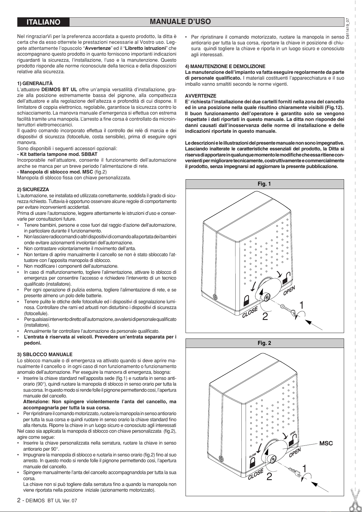
Manovra manuale:.................................... Sblocco meccanico a manopola
N° manovre in 24 ore:.............................................................................. 30
Centralina di controllo: .............................................................. incorporata
Batterie tampone (opzionali): ..................................2 batterie da12V 1,2Ah
Condizioni ambientali: ..................................................... da -15°C a +40°C
Grado di protezione: ............................................................................IP24
Rumorosità: .................................................................................... <70dBA
Peso operatore: ........................................................... 15,4 lb (7kg (≈70N))
Dimensioni : ..................................................................................Vedi fig.2
Classe azionamento cancello................................................................. I, II
(*) Tensioni speciali di alimentazione a richiesta
3.2) Dati tecnici quadro di comando QSC-D UL (Fig.17)
Alimentazione accessori: ....................................................24V~(180 mA)
Regolazione amperostop: .........................................in chiusura e apertura
Tempo di chiusura automatica: .................................................da 3 a 120s
Tempo di lavoro:.................................................................................. 2 min
Tempo di apertura pedonale: .......................................................... 5s fisso
Pausa inversione: ..............................................................................c.a.1s
Collegamento lampeggiante:................................................ 24V max 25W
Fusibili:........................................................................................ Vedi fig.17
Impostazione parametri e opzioni:...............................................................
......................tramite display LCD o programmatore palmare universale
Radioricevente Rolling-Code incorporata:............... frequenza 433.92MHz
Codice a mezzo: ........Algoritmo Rolling-Code con clonazione trasmettitori
N° combinazioni:........................................................................... 4 miliardi
Impedenza antenna:........................................................... 50Ohm (RG58)
N° max. radiocomandi memorizzabili: ..................................................... 64
3.3) Versioni trasmettitori utilizzabili:
Tutti i trasmettitori ROLLING CODE compatibili con .
4) VERIFICHE PRELIMINARI
Prima di procedere a qualsiasi operazione di installazione, verificare che la
struttura del cancello sia conforme a quanto richiesto dalle norme vigenti
ed in particolare:
• Che il binario di scorrimento del cancello sia lineare, orizzontale e le ruote
idonee a sopportare il peso del cancello.
•
Cheilcancello possaesseremossomanualmenteinmodoagevole pertutta
la sua corsa e che non si verifichino eccessivi sbandamenti laterali.
• Chela guida superiorepermetta ilgiusto giococon il cancelloper garantire
un movimento regolare e silenzioso.
• Che siano posizionate le battute di arresto in apertura e chiusura.
• Che la posizione stabilita per il fissaggio del motoriduttore, consenta di
eseguire la manovra di emergenza in modo agevole e sicuro. Nel caso
gli elementi verificati non soddisfino quanto sopra descritto, procedere
alla loro sistemazione o, se necessario, allo loro sostituzione.
ATTENZIONE: Ricordarsi che la motorizzazione è una facilitazione del-
l’uso del cancello e non risolve problemi dovuti a difetti e deficienze di
installazione o di mancata manutenzione del cancello stesso.
Togliere il prodotto dall’imballo e verificarne l’integrità. Se il prodotto non è
integro, rivolgersi alpropriorivenditore.Ricordarsidismaltirei suoi componenti
(cartone, polistirolo, nylon, ecc.) secondo le disposizioni delle norme vigenti.
5) ANCORAGGIO DELLA PIASTRA BASE
5.1) Posizione standard
• Predisporre uno scavo dove eseguire la piazzola di cemento con annegati
i tirafondi della piastra base per il fissaggio del gruppo riduttore (fig.3).
Se il binario di scorrimento è già esistente, lo scavo deve essere ricavato
in parte anche nel getto di fondazione del binario. In questo modo, un
eventuale cedimento del getto di fondazione del binario farà abbassare
anche la base del motoriduttore mantenendo così il gioco tra pignone e
cremagliera (circa 1-2mm).
• Posizionare la piastra base rispettando le quote riportate in fig.4.
Il simbolo del pignone stampigliato nella piastra base deve essere visibile
ed orientato verso il cancello. Ciò garantisce anche la corretta posizione
delle canalette per i collegamenti elettrici.
• Lasciare i tubi flessibili previsti per il passaggio dei collegamenti elettrici
sporgenti dalla piastra base.
• Per mantenere in posizione corretta la piastra base durante la posa in
opera, può risultare utile saldare due piatti di ferro sotto il binario sui quali
poi, saldare i tirafondi (fig.3).
• Eseguire un getto di calcestruzzo, facendo in modo che il getto della
piastra base faccia corpo unico con quello del binario del cancello.
• Controllare accuratamente:
Le quote di posizionamento.
Che la piastra base sia ben livellata.
Che i 4 filetti dei prigionieri siano ben puliti dal cemento.
Lasciare rapprendere il getto.
5.2) Altre posizioni
Il motoriduttore può essere posizionato in diversi modi. A titolo di esempio,
in fig.5 è rappresentato un tipo di installazione particolare. Nel caso il mo-
toriduttore non venga fissato a livello del binario di scorrimento (Posizione
standard),sidevegarantireun sicurofissaggio delmotoriduttore inrelazione
anche alla posizione del cancello, in modo da mantenere un corretto gioco
0,039”-0,078”(1-2mm) tra cremagliera e pignone. Deve essere garantito il
rispetto delle norme di sicurezza vigenti per quanto riguarda le persone,
animali e cose, e in particolare devono essere evitati rischi di infortuni dovuti
a schiacciamento, nella zona di ingranamento pignone - cremagliera ed altri
rischi meccanici.
Tutti i punti critici dovranno essere protetti da dispositivi
di sicurezza secondo quanto prevedono le normative vigenti
.
6) FISSAGGIO MOTORIDUTTORE
Quando il getto è indurito, osservando la fig.6 procedere come segue:
• Posizionare un dado M10 in ognuno dei tiranti mantenendo una distan-
za dalla base di almeno 0,098” (25mm) per permettere di abbassare il
motoriduttore ad installazione ultimata o per aggiustamenti successi del
gioco tra pignone e cremagliera.
• Posizionare un piatto “P”in dotazione in ogni coppia di tiranti e con l’ausilio
di una livella, regolare il piano nei due sensi.
• Togliereilcofanoedilcartercoprivitialmotoriduttore,eposizionareilgruppo
riduttore nei quattro tiranti con il pignone rivolto verso il cancello.
• Posizionare le quattro rondelle e avvitare i quattro dadi di bloccaggio del
motoriduttore.
• Regolare la profondità del motoriduttore facendolo scorrere nelle apposite
feritoieprevistenellabase efissarlo aduna distanzatrapignonee cancello
adeguata al tipo di cremagliera da installare. I denti della cremagliera
devono ingranare nel pignone per tutta la loro larghezza.
Al paragrafo “Montaggio della cremagliera” riportiamo le misure ed il
modo di installazione dei tipi più diffusi di cremagliera.
7) MONTAGGIO DELLA CREMAGLIERA
Al cancello, deve essere fissata una cremagliera con modulo denti 13,1
ft(m=4). Per quanto riguarda la lunghezza, questa deve contemplare, oltre
alla luce del passaggio, anche il fissaggio delle staffe per l’azionamento dei
micro finecorsa e la parte di ingranamento del pignone.Esistono diversi tipi di
cremagliera, ognunodeiqualisidiversificaperla portataedilmododi fissaggio
al cancello. La Ditta commercializza tre tipi di cremagliera che sono:
7.1) Mod. CFZ (Fig.8).
Cremaglieradiferrozincatosez.0,866”x0,866”(22x22mm)- fornitain pezzi da
DEIMOS BT UL Ver. 07 - 5
D811419_07

MANUALE PER L’INSTALLAZIONE
ITALIANO
2 metri - portata oltre i 4409,2 lb (2000kg (≈20000N)). Questi pezzi devono
essere, prima saldati ad un adeguato angolare di ferro e poi il tutto, saldato
al cancello. L’angolare, oltre a mantenere la distanza fra la cremagliera ed
il fianco del cancello, agevola la fase di fissaggio al cancello stesso, anche
se questo ha dei leggeri sbandamenti laterali. Nelle saldature di giunzione
dei vari pezzi di cremagliera, si consiglia di disporre uno spezzone di cre-
magliera come in (fig.7) per garantire il passo corretto per tutta la lunghezza
della cremagliera.
7.2) Mod. CPZ (Fig.8).
Cremagliera di plastica - sez. 0,866”x0,866”(22x22mm) - fornita in pezzi
da 3,28 ft (1m) - portata max. 1102,3 lb(500kg (≈5000N)). Questo modello
va fissato al cancello con viti normali o autofilettanti. È opportuno anche
in questo caso, interporre uno spezzone al contrario nella giunzione tra i
vari spezzi in modo da mantenere il passo corretto dei denti. Questo tipo di
cremagliera, è più silenziosa e permette regolazioni in altezza anche dopo
il fissaggio, per mezzo di feritoie previste.
7.3) Mod. CVZ (Fig.8)
Cremagliera di ferro zincato sez. 1,18x0,47 (30x12mm) fornita in pezzi da
3,28 ft (1m) - distanziali filettati a saldare - portata max. 4409,2 lb (2000kg
(≈20000N)). Fissati i distanziali in centro ad ogni asola dei vari pezzi di cre-
magliera, saldare i distanziali al cancello. Anche in questo caso, sistemare
uno spezzone al contrario nei punti di giunzione dei vari pezzi di cremagliera
per garantire il passo corretto dei denti. Le viti che fissano la cremagliera ai
distanziali, consentono regolazioni in altezza della cremagliera.
7.4) Fissaggio della cremagliera
Per il montaggio della cremagliera, eseguire quanto segue:
• Attivare lo sblocco di emergenza ruotando l’apposita manopola di sblocco
(Vedere paragrafo “Manovra di emergenza”).
• Appoggiare l’estremità della cremagliera sul pignone di comando ed ese-
guire il fissaggio (con saldatura o con viti) in corrispondenza del pignone
facendo scorrere manualmente il cancello (fig.9).
• Nel caso di cancello irregolare (eccessiva curvatura laterale), se non è
possibile correggerla, bisogna interporre degli spessori fra cremagliera
e cancello in modo da garantire sempre il centraggio della cremagliera
rispetto al pignone (fig.10).
PERICOLO - L’operazione di saldatura va eseguita da persona capace e
dotata di tutti i dispositivi di protezione individuali previsti dalle norme
di sicurezza vigenti.
8) REGOLAZIONE PIGNONE
Terminato il fissaggio della cremagliera è necessario regolare il gioco
cremagliera - pignone che deve essere di circa 0,078” (2mm) (fig.6): ciò si
ottiene allentando per circa 0,078”(2mm), i quattro dadi M10 sotto la base del
motoriduttoree fissandopoi iquattrodadi superiori.Assicurarel’allineamento
ed il centraggio della cremagliera - pignone (fig.10).
ATTENZIONE - Ricordarsi che la durata della cremagliera e del pignone
dipendono in modo determinante dal corretto ingranamento.
9) FINECORSA ELETTROMECCANICI
L’operazione va eseguita con sblocco di emergenza attivato e senza alimen-
tazione di rete. I pattini che comandano i finecorsa vanno posizionati alle
estremità della cremagliera.
- Spingere manualmente il cancello in completa apertura.
- Posizionare il pattino finecorsa di apertura (fig.11) in modo che intercetti
la leva di comando del micro e che lo facciano scattare. Individuata la
posizione corretta, serrare le viti del pattino.
- Spingere manualmente il cancello in completa chiusura.
- Posizionare il pattino finecorsa di chiusura (fig.11) in modo che intercetti
la leva di comando del micro e che lo facciano scattare.
Individuata la posizione corretta, serrare le viti del pattino.
-
Ipattini,devonobloccareilcancello,primachequestointercettiifermid’arresto
meccanici posti sulla rotaia.La regolazione del pattino finecorsa di chiusura
deve essere fatta in modo da lasciare un franco di circa 50mm fra il cancello
ed il battente fisso, come previsto dalle norme di sicurezza vigenti oppure,
applicare una costa sensibile di almeno 50mm di spessore (fig.12).
10) FERMI D’ARRESTO
PERICOLO - Il cancello deve essere dotato dei fermi d’arresto mecca-
nici sia in apertura sia in chiusura, in modo da impedire la fuoriuscita
del cancello dalla guida superiore (fig.13); devono essere solidamente
fissati a terra, qualche centimetro oltre il punto d’arresto elettrico.
11) PREDISPOSIZIONE IMPIANTO ELETTRICO
Predisporre l’impianto elettrico come indicato in fig.14 facendo riferimento
alle norme vigenti per gli impianti elettrici CEI 64-8, IEC364, armonizzazione
HD384 ed altre norme nazionali.
ATTENZIONE! Per il collegamento alla rete, utilizzare cavo multipolare
di sezione minima 3x16AWG e del tipo previsto dalle normative vigenti.
A titolo di esempio, se il cavo è all’esterno (all’aperto), deve essere
almeno pari a H07RN-F mentre, se all’interno (in canaletta),deve essere
almeno pari a H05 VV-F con sezione 3x16AWG.
Realizzare i collegamenti dei dispositivi di comando e di sicurezza in armonia
con le norme per la tecnica degli impianti precedentemente citate. I cavi
(rete e ausiliari) devono essere nettamente separati. In fig.14 è riportato il
numero di collegamenti e la loro sezione per una lunghezza di circa 328,08
ft (100 metri); per lunghezze superiori, calcolare la sezione per il carico
reale dell’automazione.
I componenti principali per una automazione sono (fig.14):
IInterruttoreonnipolareomologatodiadeguataportatacon apertura
contati di almeno 0,14”(3,5 mm) provvisto di protezione contro i
sovraccarichi ed i corti circuiti, atto a sezionare l’automazione
dalla rete. Se non presente, prevedere a monte dell’automazione
un interruttore differenziale omologato con soglia 0,03A.
QR Quadro comando e ricevente incorporata
SSelettore a chiave
AL Lampeggiante con antenna accordata
MAttuatore
PPulsantiera a muro
Fte, Fre Coppia fotocellule esterne
TTrasmittente 1-2-4 canali
CCremagliera
INSTALLAZIONE ANTENNA
Usare una antenna accordata sui 433MHz.
Per il collegamento Antenna-Ricevitore usare cavo coassiale RG58.
La presenza di masse metalliche a ridosso dell’antenna, può disturbare la
ricezione radio.In caso di scarsa portata del trasmettitore, spostare l’antenna
in un punto più idoneo.
12) COLLEGAMENTI MORSETTIERA
Passati gli adeguati cavi elettrici nelle canalette e fissati i vari componenti
dell’automazione nei punti prescelti, si passa al loro collegamento secondo
le indicazioni e gli schemi riportati nei relativi manuali istruzione. Effettuare
la connessione della fase, del neutro e della terra (obbligatoria). Il cavo di
rete va bloccato nell’apposito pressacavo (fig.15-rif.P1), i cavi degli accessori
nel pressacavo (fig.15-rif.P2), il conduttore di protezione (terra) con guaina
isolante di colore giallo/verde, deve essere collegato nell’apposito serrafilo
(fig.15-rif.S). L’automazione va messa in funzione quando sono collegati e
verificati tutti i dispositivi di sicurezza. Vedi schema morsettiera fig.16.
JP2
1-2 Collegamento motore (1 Blu - 2 Rosso).
3-4 Secondario trasformatore 24V.
ATTENZIONE - Se il verso di apertura non è corretto, invertire i col-
legamenti 1 e 2 del motore ed i collegamenti 6 e 7 dei finecorsa di
apertura e chiusura.
JP3
5-6 Fine corsa chiusura SWC (5 Nero comune - 6 Rosso).
5-7 Fine corsa apertura SWO (5 Nero comune - 7 Marrone).
8-9 Lampeggiante 24V max 25W.
10-11 Antenna (10 segnale - 11 calza).
12-13 Alimentazione accessori:
24 V~funzionamento in presenza di rete.
24 V (12+,13-) funzionamento in assenza di rete e kit opzionale
batteria tampone. Mod. SB BAT.
14-15 Uscita 24 Vac per segnale acustico (Fig.19A).
16-17 Uscita alimentazione dispositivi di sicurezza (trasmettitore fotocellule
e trasmettitore costa sensibile).
N.B.: uscita attiva solo durante il ciclo di manovra.
24 V~funzionamento in presenza di rete.
24 V (16-,17+) funzionamento in assenza di rete e kit opzionale
batteria tampone. Mod. SB BAT.
18 Ingresso dispositivi di sicurezza FAULT (vedere punto 13).
19-20 Pulsante comando pedonale PED (N.O.) Apre il cancello per un tempo
di 5 secondi con le modalità della logica impostata (3o 4 passi).
21-22 Pulsante di comando START/CLOSE e selettore a chiave (N.O.).
21-23 Pulsante di comando STOP (N.C.).In ogni caso, arresta l’automazione
fino a nuovo start. Se non si usa, lasciare ponticellato.
24 Ingresso PHOT, fotocellula e costa sensibile (vedere punto 13).
21-25 Ingresso contatto costa sensibile BAR (N.C.). In caso di intervento
si ha l’arresto e l’inversione per circa 3s. Se non si usa, lasciare
ponticellato.
21-26 Pulsante di comando APRE (Open) (N.O.).
JP1
31-32 Primario trasformatore 120V~.
33-34 Alimentazione monofase 120V~, 60 Hz (33N - 34L).
13) COLLEGAMENTO DISPOSITIVI DI SICUREZZA
Nota:utilizzaresolamentedispositividi sicurezza riceventicon contatto
in libero scambio (rif. particolare figura 19).
Per il collagamento dei dispositivi di sicurezza verificati, fare riferimento allo
schema riportato in Fig.19, considerando il numero di coppie impiegate: 1
coppia riquadro 1C, 2 coppie riquadro 2C, 3 coppie riquadro 3C e 4 coppie
riquadro 4C. La centralina esegue il test di 3 o 4 dispositivi di sicurezza solo
con la scheda aggiuntiva SCS1-MA (vedi Fig.21). I dispositivi aggiuntivi de-
vono essere con autodiagnosi interna e collegati in serie tra loro. Nel caso
6 - DEIMOS BT UL Ver. 07
D811419_07

non vengano utilizzate, lasciare i ponticelli a filo tra i morsetti 21/23, 21/24
e tra i morsetti 21/25 della scheda QSC D UL.
14) PROGRAMMAZIONE
Il quadro comandi dotato di microprocessore, viene fornito con parametri di
funzionamento preimpostati dal costruttore, validi per installazioni standard.
I parametri predefiniti possono essere variati mediante il programmatore a
display incorporato o mediante programmatore palmare universale.
Nel caso la programmazione venga effettuata mediante programmatore
palmare universale, leggere attentamente le istruzioni relative al program-
matore palmare universale e procedere come segue.
Collegare il programmatore palmare universale alla centrale tramite l’ac-
cessorio UNIFLAT e UNIDA (Vedere fig.17). La centrale QSC-D UL non
alimenta il programmatore palmare universale che quindi necessita di
apposito alimentatore.
Entrare nel menù “CENTRALINE”, nel sottomenù “PARAMETRI” e scorrere
le schermate del display con le frecce su/giù impostando numericamente i
valori dei parametri di seguito elencati.
Per le logiche di funzionamento, riferirsi al sottomenù “LOGICA”.
Nel caso si proceda alla programmazione mediante il programmatore incor-
porato fare riferimento alla Fig. A e B e al paragrafo “configurazione”.
N.B.: La centralina QSC-D UL non può alimentare il programmatore
palmare universale.
15) CONFIGURAZIONE
Il programmatore a display consente di impostare tutte le funzioni del quadro
comandi QSC-D UL.
Il programmatore dispone di tre pulsanti per la navigazione tra i menu e la
configurazione dei parametri di funzionamento:
+ tasto scorrimento menu/incremento valore
- tasto scorrimento menu/riduzione valore
OK tasto di invio (conferma)
La pressione simultanea dei tasti + e - consente di uscire menu in cui si sta
operando e passare al menu superiore.
Le modifiche apportate vengono impostate solo se seguite dalla pressione
del tasto OK.
Con la prima pressione del tasto OK si entra in modalità programmazione.
Inizialmente sul display compaiono le seguenti informazioni:
- Versione Software centrale di comando
- Numero manovre totali effettuate (il valore è espresso in centinaia quindi
durante le prime cento manovre il display indica costantemente 0000)
- Numero manovre effettuate dall’ultima manutenzione (il valore è espres-
so in centinaia quindi durante le prime cento manovre il display indica
costantemente 0000)
- Numero radiocomandi memorizzati.
Unapressione deltastoOK durantelafasedi presentazioneinizialeconsente
di passare direttamente al primo menu.
Diseguitovengonoelencatii menu principali edirelativisottomenu disponibili.
Il parametro predefinito, è quello chiuso fra parentesi quadre [ 0 ]. Tra
parentesi rotonde viene indicata la scritta che appare sul display.
Fate riferimento alle Tabelle A e B per la procedura di configurazione.
15.1) MENU PARAMETRI (PARAMM)
- Tempo Chiusura Automatica (TCA) [10s]
Impostare numericamente il valore del tempo di apertura automatica da
3 a 120 secondi.
- Coppia motori apertura (C. ap) [ 80% ]
Impostare numericamente il valore di coppia dei motori tra 1% e 99%.
- Coppia motori chiusura (C. ch) [ 80% ]
Impostare numericamente il valore di coppia dei motori tra 1% e 99%.
- Coppia motori apertura in rallentamento (C. ap. rALL) [ 50% ]
(Parametri avanzati ⇒indirizzo 8)
Impostare numericamente il valore di coppia dei motori tra 1% e 99%.
- Coppia motori chiusura in rallentamento (C. ch. rALL) [ 50% ]
(Parametri avanzati ⇒indirizzo 9)
Impostare numericamente il valore di coppia dei motori tra 1% e 99%.
- Tempo Veloce in Apertura (T vel ap,) [ 15 s. ]
(Parametri avanzati ⇒indirizzo 6)
Impostareiltempoa velocitàdiaperturanormale (nonrallentata), variabile
da 1 secondo a 2 min.
- Tempo Veloce in Chiusura (T vel ch,) [ 15 s. ]
(Parametri avanzati ⇒indirizzo 7)
Impostareiltempoa velocitàdichiusuranormale(nonrallentata), variabile
da 1 secondo a 2 min.
Nota: Il tempo di rallentamento, in chiusura e in apertura, si ottiene cro-
nometrando la durata di una manovra, ed impostando un valore minore
in questo parametro. Se ad esempio la durata di una manovra è di 15
secondi, impostando un “tempo velocità normale” di 12s si otterranno 3s
di rallentamento.
- Velocità rallentamento (vel rall,) [ 0 ]
(Parametri avanzati ⇒indirizzo 5)
Impostare la velocità di rallentamento scegliendo uno di questi valori:
0 - rallentamento disabilitato
1 - rallentamento al 50% della velocità normale
2 - rallentamento al 33% della velocità normale
3 - rallentamento al 25% della velocità normale
- Zona (Zone) [ 0 ]
(Parametri avanzati ⇒indirizzo 1)
Impostare il numero di zona tra un valore minimo di 0 ed un valore mas-
simo di 127. Vedi paragrafo “Connessione seriale”.
15.2) MENU LOGICHE (LOGIC)
- TCA (TCA) [ OFF ]
ON Attiva la chiusura automatica
OFF Esclude la chiusura automatica.
- 3 Passi (3 Passi) [ OFF ]
ON Abilita la logica 3 passi. Un impulso di start ha i seguenti effetti:
porta chiusa:............................................................................... apre
in apertura:...................... ferma ed inserisce il TCA (se configurato)
porta aperta: ...........................................................................chiude
in chiusura:..................................................................ferma e riapre
OFF Abilita logica 4 passi. Un impulso di start ha i seguenti effetti:
porta chiusa:............................................................................... apre
in apertura:...................... ferma ed inserisce il TCA (se configurato)
porta aperta: ...........................................................................chiude
in chiusura:................................... ferma e non inserisce il tca (stop)
dopo stop:................................................................................... apre
- Blocca Impulsi (BlImp) [ OFF ]
ON L’impulso di start non ha alcun effetto durante la fase di apertura.
OFF L’impulso di start ha effetto durante la fase di apertura o chiusura.
- Fotocellule in apertura (Fotoc ap) [ OFF ]
ON: in caso di oscuramento, esclude il funzionamento della fotocellula in
apertura. In fase di chiusura, inverte immediatamente.
OFF: in caso di oscuramento, le fotocellule sono attive sia in apertura che
in chiusura. Un oscuramento della fotocellula in chiusura, inverte il
moto solo dopo il disimpegno della fotocellula.
- Test fotocellule (test phot) [ OFF ]
(Logiche avanzate ⇒indirizzo 14)
ON Attiva la verifica delle fotocellule
OFF Disattiva la verifica delle fotocellule
Se disabilitato (OFF) inibisce la funzione di verifica delle fotocellule,
consentendo la connnessione di dispositivi non dotati di contatto
supplementare verifica.
- Preallarme (preall) [ OFF ]
ON
Il lampeggiante si accende circa 3 secondi prima della partenza dei
motori.
OFF
Il lampeggiante si accende contemporanteamente alla partenza dei
motori.
- Uomo presente (uomo pres) [ OFF ]
ON Funzionamento a uomo presente: la manovra continua finché viene
mantenuta la pressione sul tasto di comando. (OPEN-CLOSE).
OFF Funzionamento a impulsi, secondo la logica 3 o 4 passi.
- Selezione START - CLOSE (start - close) [ OFF ]
ON L’ingresso tra i due morsetti 21-22 funziona come CLOSE.
OFF L’ingresso tra i due morsetti 21-22 funziona come START.
- Codice Fisso (codice fisso) [ OFF ]
(Logiche avanzate ⇒indirizzo 13)
ON
Il ricevitore risulta configurato per il funzionamento in modalità codice
fisso.
OFF Il ricevitore risulta configurato per il funzionamento in modalità rolling-
code.
- Programmazione radiocomandi (prog radio) [ ON ]
(Logiche avanzate ⇒indirizzo 15)
ON Abilita la memorizzazione via radio dei trasmettitori:
1- Premere in sequenza il tasto nascosto (P1) e il tasto normale (T1-
T2-T3-T4) di un trasmettitore già memorizzato in modalità standard
attraverso il menu radio.
2- Premere entro 10s il tasto nascosto (P1) ed il tasto normale (T1-
T2-T3-T4) di un trasmettitore da memorizzare.
La ricevente esce dalla modalità programmazione dopo 10s, entro
questo tempo è possibile inserire ulteriori nuovi trasmettitori.
Questa modalità non richiede l’accesso al quadro comando.
OFF Disabilita la memorizzazione via radio dei trasmettitori.
I trasmettitori vengono memorizzati solo utilizzando l’apposito menu
Radio.
- Loop (LOOP) [ OFF ]
(Logiche avanzate ⇒indirizzo 11)
ON Nel caso di collegamento centralizzato chiuso ad anello (Fig.20),
settare la centrale su ON.
OFF
Nel caso di collegamento centralizzato aperto (Fig.20) settare la
centrale su OFF.
- Master/Slave (master) [ OFF ]
(Logiche avanzate ⇒indirizzo 12)
MANUALE PER L’INSTALLAZIONE ITALIANO
DEIMOS BT UL Ver. 07 - 7
D811419_07

ON Il quadro comando viene settato come Master in un collegamento
centralizzato (vedi Paragrafo 16).
OFF Il quadro comando viene settato come Slave in un collegamento
centralizzato (vedi Paragrafo7).
15.3) MENU RADIO (RADIO)
Nelcaso diinstallazionistandard nellequalinon sianorichieste lefunzionalità
avanzateè possibileprocedereallamemorizzazionemanualedeitrasmettitori,
facendo riferimento alla Fig.B per la programmazione base:
- Aggiungi
Consente di aggiungere un tasto di un radiocomando nella memoria della
ricevente, dopo la memorizzazione restituisce il numero della ricevente
nella locazione della memoria (da 01 a 64).
Aggiungi Tasto Start (Agg start)
associa il tasto desiderato al comando start
Nota: Il tasto nascosto P1 assume aspetto diverso a seconda del modello
di trasmettitore.
Per i trasmettitori dotati di tasto nascosto, premere il pulsante nascosto
P1 (Fig.B1). Per i trasmettitori sprovvisti del tasto nascosto, il tasto P1
corrisponde alla pressione contemporanea dei 4 tasti del trasmettitore o,
aprendo il vano batteria, a ponticellare con un cacciavite le due piazzole
P1 (Fig.B2).
- Leggi (Leggi)
Effettua una verifica di un tasto di una ricevente, se memorizzato resti-
tuisce numero della ricevente nella locazione della memoria (da 01 a
64) e numero del tasto (T1-T2-T3 o T4).
- Elimina Lista (elim. 64)
ATTENZIONE! Rimuove completamente dalla memoria della ricevente
tutti i radiocomandi memorizzati.
- Lettura codice ricevitore (cod RX)
Visualizza il codice inserito nel ricevitore.
NOTA IMPORTANTE:CONTRASSEGNARE IL PRIMOTRASMETTITORE
MEMORIZZATO CON IL BOLLINO CHIAVE (MASTER).
Il primo trasmettitore, nel caso di programmazione manuale, assegna il
CODICE CHIAVE DEL RICEVITORE; questo codice risulta necessario per
poter effettuare la successiva clonazione dei radiotrasmettitori.
Il ricevitore di bordo incorporato Clonix dispone inoltre di alcune importanti
funzionalità avanzate:
• Clonazione del trasmettitore master (rolling-code o codice fisso)
• Clonazione per sostituzione di trasmettitori già inseriti nel ricevitore
• Gestione database trasmettitori
• Gestione comunità di ricevitori
Per l’utilizzo di queste funzionalità avanzate fate riferimento alle istruzioni
del programmatore palmare universale ed alla Guida alla Programmazione
CLONIX, fornite con il dispositivo del programmatore palmare universale.
15.4) MENU LINGUA (LINGUA)
Consente di impostare la lingua del programmatore a display.
- ITALIANO (ITA)
- FRANCESE (FRA)
- INGLESE (ENG)
- SPAGNOLO (ESP)
15.5) MENU DEFAULT (DEFAULT)
Riporta la centrale ai valori preimpostati dei default. Dopo il ripristino è
necessario effettuare un nuovo autosettaggio.
15.6) DIAGNOSTICA E MONITORAGGIO
Il display presente sul quadro QSC-D UL sia nel normale funzionamento,
sia nel caso di anomalie visualizza alcune utili informazioni.
Diagnostica:
Nel caso di malfunzionamenti il display visualizza un messaggio che indica
quale dispositivo è necessario verificare:
PED = attivazione ingresso pedonale
STRT = attivazione ingresso START
STOP = attivazione ingresso STOP
PHOT = attivazione ingresso PHOT
BAR = attivazione ingresso COSTA
FLT = attivazione ingresso FAULT fotocellule verificate
CLOS = attivazione ingresso CLOSE
OPEN = attivazione ingresso OPEN
SWO = attivazione ingresso finecorsa apertura
SWC = attivazione ingresso finecorsa chiusura
TH = attivazione protezione termica software
Nel caso l’anta incontri un’ostacolo, il quadro QSC-D UL ferma e comanda
un’inversione, simultaneamente il display visualizza il messaggio “AMP”.
Monitoraggio:
Nelle fasi di apertura e chiusura il display visualizza quattro cifre separate
da un punto, ad es.
35.40.
Le cifre si aggiornano costantemente durante la
manovra e rappresentano la coppia massima raggiunta rispettivamente dal
motore (
35
) e la coppia impostata (
40
).
Questi valori consentono di correggere l’impostazione della coppia.
Se il valore di coppia massimo raggiunto durante la manovra si avvicina
sensibilimente al valore impostato nel menu parametri, potrebbero verificarsi
in futuro anomalie di funzionamento dovute all’usura o a piccole deforma-
zioni dell’anta.
Si consiglia pertanto di verificare la coppia massima raggiunta, durante al-
cune manovre in fase di installazione ed eventulmente impostare nel menu
parametri un valore superiore di circa 15/20 punti percentuali.
15.7) MENU AUTOSETTAGGIO (AUTOset)
Consente di effettuare il settaggio automatico della Coppia motori.
ATTENZIONE! L’operazione di autosettaggio va effettuata da finecorsa di
chiusura. Se si prova ad effettuare l’Autoset in una posizione diversa, com-
parirà il messaggio di errore: “nsvc” e la manovra non sarà effettuata.
ATTENZIONE!! L’operazione di autsettaggio va effettuata solo dopo aver
verificato l’esatto movimento dell’anta (apertura/chiusura) ed il corretto
intervento dei finecorsa.
Impostare la velocità di rallentamento adeguata: non appena premuto il
pulsante OK viene visualizzato il messaggio “............”, la centrale comanda
una manovra di apertura senza rallentamento seguita da una manovra di
chiusura senza rallentamento durante le quali memorizza la durata della
corsa, di seguito la centrale comanda una seconda manovra di apertura
con rallentamento seguita da una seconda manovra di chiusura con rallen-
tamento durante le quali viene automaticamente settato il valore minimo di
coppia necessario al movimento dell’anta. Quindi la centrale imposta un
rallentamento di 8 Sec. Se la corsa è inferiore agli 8 secondi, la centrale
imposta un rallentamento della durata di metà corsa.
Durante questa fase è importante evitare l’oscuramento delle fotocellule,
l’utilizzo dei comandi START, STOP, PED, CLOS, OPEN e del display.
Al termine, se l’autosettaggio è stato effettuato con successo, la centrale
visualizza il messaggio “OK”e dopo la pressione di un qualsiasi tasto ritorna
al menu Ausettaggio.
Se invece, la centrale visualizza il messaggio“KO”significa che la procedura
di autosettaggio non è stata eseguita con successo, è necessario verificare
lo stato di usura del cancello e la regolarità del movimento delle ante e quindi
procedere ad una nuova operazione di autosettaggio.
ATTENZIONE! Durante la fase di autosettaggio la funzione di rilevamento
ostacoli non è attiva, quindi l’installatore deve controllare il movimento
dell’automazione e impedire a persone e cose di avvicinarsi o sostare nel
raggio di azione dell’automazione.
In caso di utilizzo di batterie tampone l’autosettaggio deve essere effettuato
con quadro comando alimentato a tensione di rete.
ATTENZIONE: i valori di coppia impostati dall’autosetaggio sono
riferiti alla velocità di rallentamento impostata dall’autosetaggio.
Se si modifica la velocità di rallentamento, occorre modificare anche i
valori di coppia in rallentamento in modo da garantire l’intervento della
protezione con la nuova velocità impostata.
Una errata impostazione della sensibilità può creare danni a
persone, animali o cose.
16) CONNESSIONE SERIALE MEDIANTE SCHEDA SCS1 (Fig.20)
Il quadro di comando QSC-D UL consente, tramite appositi ingressi e uscite
seriali (scheda SCS1), la connessione centralizzata di più automazioni. In
questo modo è possibile, con un unico comando, eseguire l’apertura o la
chiusura di tutte le automazioni connesse.
Seguendo lo schema di Fig.20, procedere alla connessione di tutti i quadri co-
mando QSC-D UL, utilizzando esclusivamente un doppino di tipo telefonico.
Nel caso si utilizzi un cavo telefonico con più coppie risulta indispensabile
utilizzare i fili della stessa coppia.
Lalunghezzadelcavotelefonicofraunaapparecchiaturae lasuccessiva
non deve eccedere i 250 m.
A questo punto è necessario configurare opportunamente ogni quadro co-
mando QSC-D: impostare la prima centrale, che avrà il controllo di tutte le
altre, come MASTER; e le altre come SLAVE (vedi menu logiche).
Impostare inoltre il numero di Zona (vedi menu parametri) tra 0 e 127.
Il numero di zona consente di creare dei gruppi di automazioni, ognuna delle
quali risponde al Master di Zona. Ogni zona può avere un solo Master, il
Master della zona 0 controlla anche gli Slave delle altre zone.
La chiusura ad anello della connessione seriale (indicata con un tratteggio
in Fig.20), è necessaria solamente se si desidera, tramite il programmatore
palmare universale, verificare il numero dei dispositivi collegati.
16.1) Ante scorrevoli contrapposte (Fig.20A)
Tramite connessione seriale è possibile inoltre realizzare il controllo centra-
lizzato di due cancelli scorrevoli contrapposti (Fig.20A).
In questo caso il quadro comando Master M1 comanderà simultaneamente
la chiusura e l’apertura del quadro comando Slave M2.
Nel caso di ante scorrevoli contrapposte il quadro comando M1 (MASTER)
ed il quadro M2 (SLAVE) devono avere lo stesso numero di zona e nella
stessa zona non ci devono essere altri dispositivi collegati.
MANUALE PER L’INSTALLAZIONE
ITALIANO
8 - DEIMOS BT UL Ver. 07
D811419_07

Se il verso di apertura di uno dei due motori non è corretto, invertire i colle-
gamenti 1 e 2 del motore ed i collegamenti 6 e 7 dei finecorsa di apertura
e chiusura.
Idispositividi sicurezza(fotocellulee costesensibili)dovrannoessre collegati
secondo lo schema di Fig. 20A.
Perilcollegamentodidispositividisicurezzaverificati,fareriferimentoaquanto
detto in precedenza nel paragrafo 13. Effettuare i collegamenti sulla centrale
MASTER e riportare sulla centrale SLAVE solo il conduttore del morsetto 24.
Sulla centrale SLAVE il TEST PHOT dev’essere lasciato OFF.
I pulsanti Start, Open, Close, e il contatto Timer andranno normalmente
collegati al quadro M1 (MASTER).
Il comando pedonale andrà collegato al quadro M2 (SLAVE).
Il comando Stop, per una maggiore sicurezza, utilizzerà un pulsante a
doppio contatto NC collegato ad entrambi i quadri comando come indicato
in Fig.20A.
NOTA: Disabilitare il TCA del quadro M2 (slave).
17) STATISTICHE
Collegato il programmatore palmare universale alla centrale, entrare nel
menù CENTRALE / STATISTICHE e scorrere la schermata dei parametri
statistici:
- Versione software microprocessore scheda.
-
Numero cicli effettuati. Se si sostituiscono i motori, annotarsi il numero
di manovre eseguite fino a quel momento.
- Numero cicli effettuati dall’ultima manutenzione. Viene azzerato auto-
maticamente ad ogni autodiagnosi o scrittura parametri.
-
Data ultima manutenzione. Da aggiornare manualmente dall’apposito
menù “ Aggiorna data di manutenzione”.
- Descrizione impianto. Permette di inserire 16 caratteri di individuazione
impianto.
18) ALLARME
L’attuatore è provvisto di una sirena d’allarme gestita dal quadro controllo.
L’allarme entra in funzione nel caso di doppio intervento del dispositivo di
rilevamento ostacoli (amperostop), senza che l’anta venga portata in com-
pleta apertura o chiusura.
In caso di anomalie di funzionamento, l’attivazione dell’allarme arresta
immediatamente qualsiasi manovra.
E’ possibile interrompere il segnale acustico utilizzando il pulsante STOP.
Nel caso di attivazione dell’allarme è necessario procedere alle seguenti
verifiche:
1) Controllare che l’anta non abbia incontrato ostacoli.
2)
Controllare che il binario di scorrimento sia pulito e libero da eventuali
detriti per tutta la corsa dell’anta.
3) Controllare che le ruote di scorrimento sull’anta siano integre e corretta-
mente posizionate sul binario.
19) SBLOCCO MANUALE
Lo sblocco manuale o di emergenza va attivato quando si deve aprire
manualmente il cancello ed in ogni caso di non funzionamento o fun-
zionamento anomalo dell’automazione. Per eseguire la manovra di
emergenza, bisogna:
• Inserire la manopola di sblocco nell’apposita sede (fig.18) e ruotarla in
senso orario per tutta la sua corsa.In questo modo si rende folle il pignone
permettendo cosi, l’apertura manuale del cancello.
Attenzione:Non spingere violentemente l’anta del cancello, ma accom-
pagnarla per tutta la sua corsa.
•
Per ripristinare il comando motorizzato, ruotare la manopola in senso an-
tiorario per tutta la sua corsa, togliere la manopola e depositarla in luogo
sicuro e conosciuto a tutti gli interessati.Nel caso sia applicata la manopola
di sblocco con chiave personalizzata (fig.18), agire come segue:
• Inserire la chiave personalizzata nella serratura, ruotare la chiave in senso
antiorario.
• Impugnare la manopola di sblocco e ruotarla in senso orario (fig.18) fino
al suo arresto.
• Spingere manualmente l’anta del cancello accompagnandola per tutta la
sua corsa.
La chiave non si può togliere dalla serratura fino a quando la manopola
non viene riportata nella posizione iniziale (azionamento motorizzato).
• Per ripristinare il comando motorizzato, ruotare la manopola in senso
antiorario per tutta la sua corsa e togliere la chiave.
20) VERIFICA DELL’AUTOMAZIONE
Prima di rendere definitivamente operativa l’automazione, controllare scru-
polosamente quanto segue:
• Controllare il corretto funzionamento di tutti i dispositivi di sicurezza
(micro-finecorsa, fotocellule, coste sensibili ecc.).
• Verificare che la spinta (antischiacciamento) dell’anta sia entro i limiti
previsti dalle norme vigenti.
• Verificare il comando di apertura manuale.
• Verificare l’operazione di apertura e chiusura con i dispositivi di comando
applicati.
• Verificare la logica elettronica di funzionamento normale e personalizzata.
MANUALE PER L’INSTALLAZIONE ITALIANO
•
E’ richiesta l’installazione dei due cartelli forniti nella zona del cancello
ed in una posizione nella quale risultino chiaramente visibili (Fig.12).
21) USO DELL’AUTOMAZIONE
Poiché l’automazione può essere comandata a distanza mediante radioco-
mando o pulsante di Start, è indispensabile controllare frequente- mente la
perfetta efficienza di tutti i dispositivi di sicurezza. Per qualsiasi anomalia di
funzionamento, intervenirerapidamenteavvalendosi dipersonalequalificato.
Si raccomanda di tenere i bambini a debita distanza dal raggio d’azione
dell’automazione.
22) COMANDO
L’utilizzo dell’automazione consente l’apertura e la chiusura della porta in
modo motorizzato. Il comando può essere di diverso tipo (manuale, con
radiocomando, controllo accessi con badge magnetico, ecc.) secondo le
necessità e le caratteristiche dell’installazione.Per i vari sistemi di comando,
vedere le relative istruzioni.
Gli utilizzatori dell’automazione devono essere istruiti al comando e all’uso.
23) MANUTENZIONE
Per qualsiasi manutenzione, togliere alimentazione al sistema.
• Eseguire saltuariamente la pulizia delle ottiche delle fotocellule.
• Far controllare da personale qualificato (installatore) la corretta regola-
zione della coppia motori.
• Per qualsiasi anomalia di funzionamento non risolta, togliere alimentazio-
ne al sistema e chiedere l’intervento di personale qualificato (installatore).
Nel periodo di fuori servizio, attivare lo sblocco manuale per consentire
l’apertura e la chiusura manuale.
24) DEMOLIZIONE
ATTENZIONE!Avvalersiesclusivamentedipersonalequalificato.L’eliminazio-
ne dei materiali va fatta rispettando le norme vigenti.Nel caso di demolizione
dell’automazione non esistono particolari pericoli o rischi derivanti dall’auto-
mazione stessa.È opportuno, in caso di recupero dei materiali, che vengano
separati per tipologia (parti elettriche - rame - alluminio - plastica - ecc.).
25) SMANTELLAMENTO
ATTENZIONE ! Avvalersi esclusivamente di personale qualificato.
Nel caso l’automazione venga smontata per essere poi rimontata in altro
sito bisogna:
• Togliere l’alimentazione e scollegare tutto l’impianto elettrico esterno.
• Nel caso alcuni componenti non possano essere rimossi o risultino
danneggiati, provvedere alla loro sostituzione.
AVVERTENZE
Il buon funzionamento dell’attuatore è garantito solo se vengono
rispettate i dati riportati in questo manuale. La ditta non risponde dei
danni causati dall’inosservanza delle norme di installazione e delle
indicazioni riportate in questo manuale.
Le descrizioni e le illustrazioni del presente manuale non sono impe-
gnative. Lasciando inalterate le caratteristiche essenziali del prodotto,
la Ditta si riserva di apportare in qualunque momento le modifiche che
essa ritiene convenienti per migliorare tecnicamente, costruttivamente
e commercialmente il prodotto, senza impegnarsi ad aggiornare la
presente pubblicazione.
DEIMOS BT UL Ver. 07 - 9
D811419_07

.P+
*M%'A
OK
+ -
+ -
MENU SEGUENTI
FIG. B
OK
-+
-+
-+
-+
-+
-+
-+
-+
-+
-+
MENU PARAMETRI
TCA valore espresso in secondi
(default 10=10s, min 3=3s, max 120=120s)
Coppia Mot apertura valore espresso
in % (default 80%, min 1%, max 99%)
Coppia Mot chiusura valore espresso
in % (default 80%, min 1%, max 99%)
Coppia Mot apertura in rall. val. espr.
in % (default 50%, min 1%, max 99%)
Coppia Mot chiusura in rall.val. espr.
in % (default 50%, min 1%, max 99%)
Tempo veloce in apertura
valore espresso in secondi
(default 15=15s, min 1=1s, max 2=2min)
Tempo veloce in chiusura
valore espresso in secondi
(default 15=15s, min 1=1s, max 2=2min)
Rallentamento valore numerico
(default 0, min 0, max 3)
Zona valore numerico
(default min 0, max 127)
.P%
[]
OK OK
RA
OK OK
[]
.P%
A.
OK OK
[]
.P%
AAF
-+
OK
RA ON
OFF
[M$$]
.P%
OK
OK
.11' ON
OFF
[M$$]
.P%
OK
OK
@J'+. ON
OFF
[M$$]
.P%
OK
OK
$MRMA. ON
OFF
[M$$]
.P%
OK
OK
R#QR.FMR ON
OFF
[M$$]
.P%
OK
OK
.P#**
ON
OFF
[M$$]
.P%
OK
OK
SMKMNPCQCLRC
OK
ON
OFF
[M$$]
.P%
OK
QR?PRAJMQC
ON
OFF
[M$$]
.P%
OK
-+
OK
.PM%PB'M ON
OFF
[ML ]
.P%
OK
-+
-+
OK
AMB$'11M ON
OFF
[M$$]
.P%
OK
-+
OK OK
[]
.P%
RT#*LMPK.
OK OK
[]
.P%
RT#*LMPKAF
-+
-+
OK OK
[ ]
.P%
T#*P**
OK OK
8MLC []
.P%
-+
OK OK
[]
.P%
A.P**
-+
OK OK
[]
.P%
AAFP**
-+
OK
+1R#P ON
OFF
[M$$]
.P%
OK
-+
OK
*MM. ON
OFF
[M$$]
.P%
OK
Fig. A
+-
$',#
+-
$',#
OK
Premere il tasto OK
$2
OQABSJ
OK
ACCESSO AI MENU
Versione software centrale
Nomanovre totali (in centinaia)
Nomanovre da ultima
manutenzione (in centinaia)
Noradiocomandi memorizzati
LEGENDA
[ ]
Incremento/riduzione parametri o
commutazione ON/OFF
Scorrimento menu
(+ = precedente - = successivo)
Premere tasto OK (Invio/conferma)
Messaggio OK! (conferma avvenuta modifica)
.0%
OK
+-
-+
/ON
/OFF
Messaggio KO! (errore valore o funzione)
.0%
Messaggio "Attesa" (inserire valore o funzione)
OK
Premere simultaneamente i tasti + e -.
Lapressione simultanea deitasti+ e-
consente di uscire dal menu in cui si sta
operando e tornare al precedente, se avviene
al livello principale del menu esce dalla
programmazione e spegne il display.
Le modifiche apportate vengono confermate
solo se seguite dalla pressione del pulsante OK.
Valore preimpostato
10 - DEIMOS BT UL Ver. 07
D811419_07

Fig. B
"#$3*2
0"'-
MENU AUTOSET
Imposta automaticamente la coppia motori.
ATTENZIONE! Durante la fase di autosettaggio la
funzione di rilevamento ostacoli non è attiva,
l’installatoredevecontrollareilmovimento
dell’automazione e impedire a persone e cose di
avvicinarsiosostarenelraggiodiazione
dell’automazione.
MENU PRECEDENTI
FIG. B
OK OK
-+
-+
-+
-+
+/-
$',#
+/-
$',#
OK
+/-
OK
32-QCR
+/-
$',#
*',%3
'2
$0
#,%
CQN
OK OK
OK
OK
OK
+/-
$',#
-+
-+
-+
OK
OK
.0%
Premere P1 del radioco-
mando
Premere T desiderato del
radiocomando vedi Fig.B3
Premere T desiderato del
radiocomando vedi Fig.B3
Rilasciare P1 del
radiocomando
EEQR?PR
R?QRML?QAMQRM PGJ?QAG?
R?QRMBCQGBCP?RM
.0%
*CEEG
MENU RADIO
AGGIUNGI- Consente di aggiungere un tasto di un
radiocomando nella memoria della ricevente, dopo la
memorizzazione restituisce numero del trasmettitore
nella locazione della memoria (da 01 a 64).
Aggiungi Tasto start - associa il tasto desiderato al
comando Start
LEGGI- Effettua una verifica di un tasto di una
ricevente, se memorizzato restituisce numero della
ricevente nella locazione della memoria (da 01 a 64) e
numero del tasto (T1-T2-T3 o T4).
ELIMINA 64
ATTENZIONE! Rimuove completamente dalla
m e m o r i a d e l l a r i c e v e n t e t u t t i i r a d i o c o m a n d i
memorizzati
COD RX
Visualizza il codice ricevitore.
Fare riferimento al paragrafo11.
OK
OK
OK
#JGKGL?
-+
-+
!-"06
OK
!
OK
$"
OK
OK
-+
+/-
R
T1
T2
T1
T2
T3
T4
P1
1 2 3
T1 T2 T1 T2
T3T4
P1
P1
.P+
*M%'A
OK
+ -
+ -
MENU SEGUENTI
FIG. B
OK
-+
-+
-+
-+
-+
-+
-+
-+
-+
-+
MENU PARAMETRI
TCA valore espresso in secondi
(default 10=10s, min 3=3s, max 120=120s)
Coppia Mot apertura valore espresso
in % (default 80%, min 1%, max 99%)
Coppia Mot chiusura valore espresso
in % (default 80%, min 1%, max 99%)
Coppia Mot apertura in rall. val. espr.
in % (default 50%, min 1%, max 99%)
Coppia Mot chiusura in rall.val. espr.
in % (default 50%, min 1%, max 99%)
Tempo veloce in apertura
valore espresso in secondi
(default 15=15s, min 1=1s, max 2=2min)
Tempo veloce in chiusura
valore espresso in secondi
(default 15=15s, min 1=1s, max 2=2min)
Rallentamento valore numerico
(default 0, min 0, max 3)
Zona valore numerico
(default min 0, max 127)
.P%
[]
OK OK
RA
OK OK
[]
.P%
A.
OK OK
[]
.P%
AAF
-+
OK
RA ON
OFF
[M$$]
.P%
OK
OK
.11' ON
OFF
[M$$]
.P%
OK
OK
@J'+. ON
OFF
[M$$]
.P%
OK
OK
$MRMA. ON
OFF
[M$$]
.P%
OK
OK
R#QR.FMR ON
OFF
[M$$]
.P%
OK
OK
.P#**
ON
OFF
[M$$]
.P%
OK
OK
SMKMNPCQCLRC
OK
ON
OFF
[M$$]
.P%
OK
QR?PRAJMQC
ON
OFF
[M$$]
.P%
OK
-+
OK
.PM%PB'M ON
OFF
[ML ]
.P%
OK
-+
-+
OK
AMB$'11M ON
OFF
[M$$]
.P%
OK
-+
OK OK
[]
.P%
RT#*LMPK.
OK OK
[]
.P%
RT#*LMPKAF
-+
-+
OK OK
[ ]
.P%
T#*P**
OK OK
8MLC []
.P%
-+
OK OK
[]
.P%
A.P**
-+
OK OK
[]
.P%
AAFP**
-+
OK
+1R#P ON
OFF
[M$$]
.P%
OK
-+
OK
*MM. ON
OFF
[M$$]
.P%
OK
Fig. A
+-
$',#
+-
$',#
OK
Premere il tasto OK
$2
OQABSJ
OK
ACCESSO AI MENU
Versione software centrale
Nomanovre totali (in centinaia)
Nomanovre da ultima
manutenzione (in centinaia)
Noradiocomandi memorizzati
LEGENDA
[ ]
Incremento/riduzione parametri o
commutazione ON/OFF
Scorrimento menu
(+ = precedente - = successivo)
Premere tasto OK (Invio/conferma)
Messaggio OK! (conferma avvenuta modifica)
.0%
OK
+-
-+
/ON
/OFF
Messaggio KO! (errore valore o funzione)
.0%
Messaggio "Attesa" (inserire valore o funzione)
OK
Premere simultaneamente i tasti + e -.
Lapressione simultanea deitasti+ e-
consente di uscire dal menu in cui si sta
operando e tornare al precedente, se avviene
al livello principale del menu esce dalla
programmazione e spegne il display.
Le modifiche apportate vengono confermate
solo se seguite dalla pressione del pulsante OK.
Valore preimpostato
DEIMOS BT UL Ver. 07 - 11
D811419_07

INSTALLATION MANUAL
ENGLISH
Thank you for buying this product, our company is sure that you will be more
than satisfied with the product’s performance. The product is supplied with
a “Warnings” leaflet and an “Instruction booklet”. These should both be
read carefully as they provide important information about safety, installa-
tion, operation and maintenance.This product complies with the recognised
technical standards and safety regulations.
1) GENERAL SAFETY
WARNING! An incorrect installation or improper use of the product
can cause damage to persons, animals or things.
• The “Warnings” leaflet and “Instruction booklet” supplied with this
product should be read carefully as they provide important information
about safety, installation, use and maintenance.
• Scrap packing materials (plastic, cardboard, polystyrene etc) according
to the provisions set out by current standards. Keep nylon or polystyrene
bags out of children’s reach.
• This product was exclusively designed and manufactured for the use
specified in the present documentation. Any other use not specified in
this documentation could damage the product and be dangerous.
• The Company declines all responsibility for any consequences resulting
from improper use of the product, or use which is different from that
expected and specified in the present documentation.
• Do not install the product in explosive atmosphere.
• The Company declines all responsibility for any consequences resulting
fromfailuretoobserveGoodTechnical Practicewhenconstructing closing
structures (door, gates etc.), as well as from any deformation which might
occur during use.
• Disconnect the electrical power supply before carrying out any work on
the installation. Also disconnect any buffer batteries, if fitted.
• Fit an omnipolar or magnetothermal switch on the mains power supply,
having a contact opening distance equal to or greater than 3,5 mm.
• Check that a differential switch with a 0.03A threshold is fitted just before
the power supply mains.
• Check that earthing is carried out correctly: connect all metal parts for
closure (doors, gates etc.) and all system components provided with an
earth terminal.
• Fitall the safety devices (photocells,electric edges etc.)which areneeded
to protect the area from any danger caused by squashing, conveying and
shearing.
• Position at least one luminous signal indication device (blinker) where it
can be easily seen, and fix a Warning sign to the structure.
•
TheCompany declinesall responsibilitywith respectto theautomation safety
and correct operation when other manufacturers’ components are used.
• Only use original parts for any maintenance or repair operation.
• Do not modify the automation components, unless explicitly authorised
by the company.
• Instruct the product user about the control systems provided and the
manual opening operation in case of emergency.
•
Do not allow persons or children to remain in the automation operation
area.
• Keep radio control or other control devices out of children’s reach, in
order to avoid unintentional automation activation.
• The user must avoid any attempt to carry out work or repair on the automa-
tion system, and always request the assistance of qualified personnel.
• Anything which is not expressly provided for in the present instructions,
is not allowed.
• Installation must be carried out using the safety devices and controls
prescribed by the EN 12978 Standard.
2) GENERAL OUTLINE
The DEIMOS BT UL actuator offers ample installation versatility thanks
to its compactness, the extremely low position of its pinion as well as the
height and depth adjustments available. The adjustable electronic torque
limiter ensures antisquash safety.The emergency manual manoeuvre can be
activated very easily by means of a knob. The end-of-run stop is controlled
by electromechanical limit microswitches. The control unit is incorporated.
Before each manoeuvre, the control unit performs a check of the operation
relays and safety devices (photocells, rubber skirt, etc.).
The gearmotor (fig.1) comprises:
The incorporated control panel checks the drive relays and safety devices
(photocells and safety edge) before carrying out any manoeuvre.
MMotor.
RReduction gear with worm screw and wheel.
FElectromechanical limit switch unit.
PPinion.
SRelease mechanism.
QSC-D UL Control panel
The following optional accessories are available:
- SBBAT mod. Buffer battery kit
It can be incorporated into the actuator and allows the automation system
to operate even when the mains power supply is disconnected for a short
time. The pack includes (fig.1):
• 2 buffer batteries (ref. B).
• 1 battery holder base (ref. BB).
• 1 battery charger board (ref. SBS).
• Assembly instruction manual.
• Various bolts, screws and cables.
- MSC mod. Release knob (fig.18)
Fixed release knob with personalised key.
INSTALL THE GATE OPERATOR ONLY WHEN:
• The operator is appropriate for the construction of the gate and the usage
Class of the gate,
• All exposed pinch points are eliminated or guarded,
• The operator is intended for installation only on gates used for vehicles.
Pedestrians must supplied with a separate access opening,
• The gate must be installed in a location so that enough clearance is
supplied between the gate and adjacent structures when opening and
closing to reduce the risk of entrapment. Swinging gates shall not open
into public access areas,
• The gate must be properly installed and work freely in both directions prior
to the installation of the gate operator. Do not over-tighten the operator
clutch or presure relief valve to compensate for a damaged gate.
FOR GATE OPENERS WITH HOLD-TO-RUN CONTROL:
• The gate operator controls must be placed so that the user has full view
of the gate area when the gate is moving,
• A sign with the message “WARNING” must be positioned near the
controls. The characters for the writing should be at least 6.4 mm high.
The following statement should also be indicated: “Moving Gate Has the
Potential of Inflicting Injury or Death - Do Not Start Gate Unless Path is
Clear”.
• An automatic closing device (such as a timer, loop sensor, or similare
device) shall not be employed
• No other activation device shall be connected.
Controls must be far enough from the gate so that the user is prevented
from coming in contact with the gate while operating the controls. controls
intended to be used to reset an operator after 2 sequential activations of the
entrapment protection device or devices must be located in the line-of-sight
of the gate. Outdoor or easly accesible controls shall have a security feature
to prevent unauthorized use.
All warnings signs and placards must be installed where visible in the area
of the gate.
FORGATEOPERATOR PROVIDEDWITHSENSORFOR CONTACT-FREE
DETECTION:
• See instructions on the placement of non contact sensor for each type
of application,
• Care shall be exercised to reduce the risk of nuisance tripping, such as
when a vheicle, trips the sensor while the gate is still moving.
• One or more non-contact sensor shall be located where the risk of
entrapment or obstruction exist, such as the perimeter reachable by a
moving gate or barrier.
FOR GATE OPERATOR PROVIDEDWITH CONTACT DETECTION (RUB-
BER EDGE OR SIMILAR):
• On or more contact sensor shall be located at the pinch point of a vehicular
vertical pivot gate.
• A hardwired contact sensor shall be located and its wiring arranged so
that the communication between the sensor and the gate operator is not
subjected to mechanical damage.
• A wireless contact sensor such as one that transimts radio frequency
(RF) signals the gate operator for entrapment protection functions shall
be located where the transimission of the signals are not obscrtucted or
impeded y building structure, natural landscaping or similar obstruction.
A wireless contact sensor shall function under the intended end-use
conditions.
IMPORTANT SAFETY INSTRUCTIONS
WARNINGS: to reduce the risk of injury or death:
• Read and follow all instructions.
• Never let children operate or play with gate control. Keep the remote
control away from children.
• Always keep people and objects away from the gate. NO ONE SHOULD
CROSS THE PATH OF THE MOVING GATE.
• All openings of a horizontal slide gate are guarded or screened from the
bottom of the gate to a minimum of 4 feet (1.22 m) above the ground to
12 - DEIMOS BT UL Ver. 07
D811419_07

INSTALLATION MANUAL ENGLISH
prevent a 2-1/4 inch (57.2 mm) diameter sphere from passing through
the openings anywhere in the gate, and in that portion of the adjacent
fence that the gate covers in the open position.
• All exposed pinch points are eliminated or guarded, and guarding is
supplied for sliding gates exposed rollers.
• Test the gate operator monthly. The gate MUST reverse on contact with
a rigid object or stop when an object activates the non-contact sensors.
If the gate operator is not functioning properly, have a qualified service
technician adjust the motor torque setting or the limit of travel and retest
the gate operator.
Failure to retest and to have any necessary adjustments made to the gate
operator so it functions properly can increase the risk of injury or death.
• Use the emergency release only when the gate is not moving.
• KEEP GATES PROPERLY MAINTAINED. Read the user’s manual. Have
a qualified service person make repairs to gate hardware.
• The entrance is for vehicles only. Pedestrians must use a separate en-
trance.
• SAVE THESE INSTRUCTIONS.
3) TECHNICAL DATA
3.1) DEIMOS BT UL Actuator
Power supply: ....................................... single-phase 120V ±10% 60Hz (*)
Motor: ............................................................................................... 24Vdc
Motor revolutions: ........................................................................3500min-1
Absorbed power:.................................................................................. 70W
Max absorbed power:...................................... 0,5A (120V~) - 1A (110V~)
Reduction ratio: .................................................................................... 1/44
Output revolutions:........................................................................... 79min-1
Pinion pitch:........................................................... 0,157” (4mm) (14 teeth)
Leaf speed:....................................................................... 7,87”/s (0,2 m/s)
Max leaf weight: .............................................. 1102,3 lb (5000N) (≈500kg)
Max torque:................................................................... 14,747 lb ft (20Nm)
Impact reaction:..................................................... Electronic torque limiter
Lubrication:.................................................................... Permanent grease
Manual manoeuvre:............................................. Mechanical knob release
No. manoeuvres in 24 hours:.................................................................. 30
Control unit: ............................................................................ incorporated
Buffer batteries (optional): ........................................ 2 batteries 12V 1.2Ah
Environmental conditions:........................................... from -15°C to +40°C
Degree of protection:........................................................................... IP24
Noise:............................................................................................. < 70dBA
Controller weight:........................................................ 15,4 lb (7kg (≈70N))
Dimensions:.................................................................................. See fig.2
Class of gate operator ............................................................................ I, II
(*) Special supply voltages on request.
3.2) QSC-D UL Control unit technical data (Fig.17)
Supply to accessories:........................................................ 24V~(180 mA)
Ampere-stop setting:.............................................. on closing and opening
Automatic closing time: ........................................................ from 3 to 120s
Working time:...................................................................................... 2 min
Pedestrian opening time:................................................................ 5s fixed
Reverse pause:........................................................................... approx. 1s
Blinker connection: ............................................................... 24V max 25W
Fuses:......................................................................................... See fig.17
Parameter and option setting:......................................................................
by means of keys or universal palmtop programmer
Incorporated Rolling-Code radio receiver:............... frequency 433.92MHz
Coded by means of :.............................................. Rolling-Code Algorithm
No. combinations: ......................................................................... 4 milliard
Antenna impedance: ...........................................................50Ohm (RG58)
Max no. radio controls to be memorised:................................................ 64
3.3) Transmitter versions which can be used:
all Rolling Code transmitters compatible with .
4) PRELIMINARY CHECKS
Before proceeding to any installation work, check that the gate structure
conforms to whatever is prescribed by the current standards, and in
particular that:
• The gate sliding track is linear and horizontal, and the wheels are suitable
for supporting the gate weight.
• The gate manual operation can be carried out smoothly along its entire
run, and there is no excessive side slipping.
• A correct play is provided between the upper guide and the gate to ensure
regular noiseless movement.
• The opening and closing gate stops are positioned.
• The established position for gearmotor fixing allows the emergency ele-
ments checked do not meet the above requirements, proceed to carrying
out the necessary corrective actions or replacements.
WARNING:Rememberthatcontrol devicesare intended tofacilitategate
operation, but can not solve problems due to any defects or deficiency
resultingfromfailuretocarryoutcorrectinstallationormaintenance.Take
theproduct outof itspackingand inspectit fordamage.Should itbe damaged,
contact your dealer. Remember to dispose of its components (cardboard,
polystyrene, nylon, etc.) according to the current prescriptions.
5) BASE PLATE ANCHORING
5.1) Standard position
• Dig a hole where the cement pad with the buried base plate log bolts is to
be placed in order to fix the reduction gear unit (fig.3). If the sliding track
is already there, digging must be partly carried out in the track foundation
casting.This way, should the track foundation casting sag, the gearmotor
base would also lower, thus maintaining the play between pinion and rack
(approximately 0,039”-0,078” (1-2 mm).
• Position the base plate according to the dimensions specified in fig.4.
• The pinion symbol printed on the base plate must be visible and directed
towards the gate.This also ensures the correct positioning of the raceways
for electrical connections.
• Let the flexible pipes containing electrical cables protrude from the
base plate.
• In order to keep the base plate in its correct position during installation,
it may be useful to weld two iron flat bars under the track, and then weld
the log bolts onto them (fig.3).
• Make a concrete casting in such a way as to embody the base plate
casting into that of the gate track.
• Accurately check that:
The positioning dimensions are correct.
That the base plate is well levelled.
That the 4 stud threads are well clear of cement.
Let the casting harden.
5.2) Other positions
The gearmotor can be positioned in different ways. As an example, fig.5
illustrates a particular type of installation. In the case where the gearmotor
is not fixed on the level of the sliding track (Standard position), you must
ensure that the gearmotor is tightly secured also in relation to the gate posi-
tion, so as to maintain a correct play 0,039”-0,078” (1-2 mm) between rack
and pinion. The current safety standards with respect to persons, animals
and things must be strictly observed, and in particular risks of accidents due
to squashing in the area of pinion-rack meshing, as well as other mechanical
risks, must be carefully avoided. All the critical spots must be protected
by safety devices in compliance with the current prescriptions.
6) GEARMOTOR FIXING
When the casting has hardened, observe fig. 6 and proceed as follows:
• Position an M10 nut on each of the tie rods, keeping a distance of at least
0,098” (25mm) from the base to allow the gearmotor to be lowered after
the installation is completed, or for subsequent adjustments of the play
between pinion and rack.
• Position a plate “P”supplied as standard on each pair of tie rods and, with
the help of a level, adjust the plane in both directions.
• Remove the cover and screw-cover guard from the gearmotor, and po-
sition the reduction gear unit on the four tie rods with the pinion facing
the gate.
• Position the four washers and screw the four gearmotor locking bolts.
• Adjust the depth of the gearmotor, making it slide in the appropriate slots
found in the base, and fix it at a distance between pinion and gate which
is adequate to the type of rack to be installed.The rack teeth must mesh
into the pinion along their entire width. In the paragraph headed “Rack
fitting” we specify the measurements and installation methods of the
most widely used types of rack.
7) RACK FITTING
A rack having a 4 tooth pitch must be fitted to the gate. As far as the length
is concerned, this must include the passage space, as well as the space for
securing the brackets activating the limit microswitches, and for the pinion
meshing section. There are different types of rack, each one differing in
terms of capacity and gate fixing method. The Company markets three
types of racks, which are.
7.1) Mod. CFZ (Fig.8).
Galvanised iron rack - 0,866”x0,866 (22x22mm) section - supplied in 2
- metre lengths - capacity over 4409,2 lb (2000kg (≈20000N)). First weld
these pieces onto an adequate iron angle bar and then weld the lot to the
gate. Besides maintaining the distance between the rack and the side of the
gate, the angle bar makes it easy to fix the rack to the gate, even when the
latter is subject to slight side slipping. When join welding the various rack
pieces, you are advised to arrange a section of rack as in (fig.7) to ensure
a correct pitch along the entire length of the rack.
DEIMOS BT UL Ver. 07 - 13
D811419_07

7.2) Mod. CPZ (Fig.8).
Plastic rack - 22x22mm section - supplied in 3,28ft (1- metre) lengths - max.
capacity 1102,3lb (500kg (≈5000N)). This model is to be fixed to the gate
by means of normal or self-threading screws. Also in this case, you are
advised to insert a section of rack the other way round in the joint between
the various pieces, so as to maintain the correct tooth pitch. This type of
rack is quieter and allows height adjustments to be made even after having
been fixed, using the slots provided.
7.3) Mod. CVZ (Fig.8)
Galvanised iron rack - 1,18x0,47“(30x12mm) section - supplied in 3,28ft (1
- metre) lengths - threaded spacers to be welded - max. capacity 4409,2 lb
(2000kg (≈20000N)). Having fixed the spacers in the middle of each of the
slots in the various rack pieces, weld the spacers to the gate. Also in this
case, arrange a section of rack the other way round in the joining points of
the various rack pieces to ensure a correct tooth pitch.The screws which fix
the rack to the spacers allow the rack to be adjusted in height.
7.4) Rack fitting
To fit the rack, proceed as follows:
• Activate the emergency release by rotating the appropriate release knob
(See paragraph “Emergency manoeuvre”).
• Rest the rack end on the control pinion and secure it (by welding or using
screws) in correspondence with the pinion, while sliding the gate along
by hand (fig. 9).
•
In the case of incorrect gate alignment (excessive side curving) which
cannot be corrected, place a few shims between the rack and gate in
order to ensure continuous centring of the rack with respect to the pinion
(fig. 10).
DANGER - The welding operation is to be carried out by a competent
person who mustbe provided withallthe personalprotectionequipment
required by the current safety standards.
8) PINION ADJUSTMENT
Having finished fixing the rack, the rack-pinion play needs to be adjusted to
approximately 0,078”(2mm) (fig.6): this is obtained by slackening the four
M10 nuts under the gearmotor base by approximately 0,078”(2mm), and
then securing the four upper nuts. Make sure that the rack and pinion are
aligned and centred (fig.10).
WARNING - Remember that the rack and pinion life strictly depends
on their correct meshing.
9) ELECTROMECHANICAL LIMITING DEVICES
The operation must be carried out with the emergency release activated and
the mains power supply disconnected.The runners which control the limiting
devices are to be positioned at both ends of the rack.
- Push the gate fully open by hand.
- Position the opening end-of-stroke runner (fig.11) so that it intercepts the
microswitch control lever and makes it trigger.Having identified the correct
position, tighten the runner screws.
- Push the gate fully closed by hand.
- Position the closing end-of-stroke runner (fig.11) so that it intercepts the
microswitch control lever and makes it trigger.Having identified the correct
position, tighten the runner screws.
- The runners must lock the gate before this intercepts the mechanical
backstopsplacedonthetrack.Theclosingend-of-strokerunneradjustment
must be made in such a way as to leave a clearance of approximately
50mm between the gate and the fixed swing leaf, as prescribed by the
current safety standards, otherwise fit an electric edge at least 50mm
thick (fig.12).
10) GATE BACKSTOPS
DANGER -The gate must be provided with mechanical backstops, both
on opening and closing,in order prevent it from coming out of the upper
guide (fig.13); the backstops must be tightly secured to the ground, a
few centimetres beyond the electrical stop point.
11) ELECTRICAL INSTALLATION SETUP
Lay out the electrical installation as shown in fig.14 with reference to the CEI
64-8 and IEC364 provisions complying with the HD384 and other national
standards in force for electrical installation.
WARNING! For connection to the mains, use a multipolar cable having
a minimum cross section of 3x16 AWG and complying with the current
standards.(For example, if the cable is not protected, it must be at least
equal to H07 RN-F, whereas if it is protected it must be at least equal
to H07 VV-F with a 3x16 AWG sq cross section).
Connect the control and safety devices in compliance with the previously
mentioned technical installation standards.The cables (mains and auxiliary)
must be distinctly separated. Fig.14 shows the number of connections and
their cross sections for a length of approximately 328,08 ft(100 metres); for
greater lengths, calculate the cross section for the true automation load.
The main automation components are (fig.14):
I Type-approved adequately rated omnipolar circuit-breaker with
at least 0,14”(3,5 mm) contact opening, provided with protection
againstoverloadsandshortcircuits,suitablefor cuttingoutautoma-
tion from the mains.If not already install ed, place a type-approved
omnipolar circuit-breaker with a 0.03A threshold just before the
automation system.
QR Control panel with built-in receiver
SKey selector.
AL Blinker with tuned antenna.
MActuator
PWall-mounted pushbutton panel.
Fte, Fre Pair of external photocells.
T1-2-4 channel transmitter
C Rack
ANTENNA INSTALLATION
Use an antenna tuned to 433MHz.
For Antenna-Receiver connection, use RG8 coaxial cable.
The presence of metallic masses next to the antenna can interfere with radio
reception. In case of insufficient transmitter range, move the antenna to a
more suitable position.
12) TERMINAL CONNECTIONS
After adequate electric cables have been made to pass through the raceways
and the various automation components fixed to the chosen points, these
must be connected according to the instructions and diagrams shown in the
relevant instruction manuals. Connect the phase, neutral and earth (com-
pulsory) cables. The mains cable is to be secured in the appropriate cable
clamp (fig.15- ref. P1), the accessory cables in their cable clamp (fig.15- ref.
P2), and the protection (earth) wire, having a yellow/green insulating sheath,
must be held in its appropriate wire clamp (fig.15 - ref. S).
The automation device is to be set at work after all the safety devices have
been connected and checked. See the terminal diagram in fig.16.
JP2
1-2 Motor connection (1 Blue - 2 Red).
3-4 Transformer secondary circuit 24V.
WARNING – If the opening direction is not correct, reverse connections
1 and 2 for the motor and connections 6 and 7 for opening and closing
limit switches.
JP3
5-6 Closing limit switch SWC (5 Black common - 6 Red)
5-7 Opening limit switch SWO (5 Black common - 7 Brown)
8-9 Blinker 24V max 25W.
10-11 Antenna (10 signal - 11 braid)
12-13 Power supply for accessories:
24 V~operation with power supply on
24V (12+,13-) operation with power supply off and optional battery
back up. Mod. SB BAT
14-15 24 V~output for acoustic signal (Fig. 19A).
16-17 Output for power supply to safety devices (photocell transmitter and
safety edge transmitter)
N.B.: output only active during the manoeuvre cycle
24 V~operation with power supply on
24 V (16-,17+) operation with power supply off and optional battery
back up. Mod. SB BAT.
18 Input for safety devices FAULT (see item 13).
19-20 Pedestrian control button PED (N.O.) Opens the gate for 5 seconds
according to the logic set (3or 4 steps).
21-22 START/CLOSE control button and key selector (N.O.).
21-23 STOP control button (N.C.). In all cases, stops the operator until the
next Start command. If not used, leave bridged.
21-24 Input for photocell PHOT (see item 13). If not used, leave bridged.
21-25 BAR electricedge contactinput (N.C.).Incase oftriggering, movement
is stopped and reversed for about 3s. If not used, leave bridged.
21-26 OPEN control button (N.O.)
JP1
31-32 Transformer primary circuit 120V~.
33-34 Single-phase power supply 120V~, 60Hz (33N - 34L).
13) CONNECTION TO SAFETY DEVICES
Note:only use safety devices which can receive with a free changeover
contact (refer to Fig.19).
INSTALLATION MANUAL
ENGLISH
14 - DEIMOS BT UL Ver. 07
D811419_07

To connectthe photocells refer tothe diagramin fig.19 taking intoaccount the
number of pairs used:1 pair box 1C, 2 pairs box 2C.The control unit performs
the test of 2 safety devices. The additional devices must be equipped with
internal self-diagnosis and connected in series. If photocells are not used,
leave the jumpers aligned between terminal 21/23, and between terminal
21/24 of the QSC D UL board. The connection of the infrared rubber skirt
must be performed in the same way as for the photocells, i.e. by energizing
the transmitter from terminal 16/17 and the receiver from terminal 12/13.
14) PROGRAMMING
The control panel provided with a microprocessor is supplied with function
parameterspresetbythemanufacturer,suitableforstandardinstallations.The
predefined parameters can be altered by means of either the incorporated
display programmer or universal palmtop programmer.
In the case where programming is carried out by means of universal palmtop
programmer, carefully read the instructions relating to universal palmtop
programmer, and proceed in the following way.
Connect the universal palmtop programmer to the control unit through the
UNIFLAT and UNIDA accessories (See fig. 17). The QSC-D UL control unit
does not supply the universal palmtop programmer with power, and therefore
requires an appropriate supply unit.
Enterthe“CONTROL UNITS”menu,andthe“PARAMETERS”submenu, then
scroll the display screenfuls using the up/down arrows to set the numerical
values of the parameters listed below.
For the function logics, refer to the “LOGIC” submenu.
In the case where programming is carried out by means of the incorporated
programmer, refer to Fig. A and B and to the paragraph on “Configuration”.
N.B.:The QSC-D UL control unit cannot supply the universal palmtop
programmer with power.
15) CONFIGURATION
The display programmer is used to set all the QSC-D UL control panel
functions.
The programmer is provided with three pushbuttons for menu scrolling and
function parameter configuration:
+menu scrolling/value increment key
- menu scrolling/value reduction key
OK Enter (confirm) key
The simultaneous pressure of the + and - keys is used to exit the active
menu and move to the preceding menu.
The modifications made are only set if the OK key is subsequently pres-
sed.
When the OK key is pressed for the first time, the programming mode is entered.
The following pieces of information appear on the display at first:
- Control unit software version.
- Number of total manoeuvres carried out (the value is expressed in
hundreds, therefore the display constantly shows 0000 during the first
hundred manoeuvres).
- Number of manoeuvres carried out since the latest maintenance opera-
tion (the value is expressed in hundreds, therefore the display constantly
shows 0000 during the first hundred manoeuvres).
- Number of memorised radio control devices.
When the OK key is pressed during the initial presentation phase, the first
menu can be accessed directly.
Here follows a list of the main menus and the respective submenus available.
The predefined parameter is shown between square brackets [ 0 ].
The writing appearing on the display is indicated between round brackets.
Refer to Figures A and B for the configuration procedure.
15.1) Parameters menu
- Automatic Closing Time (TCA) [ 10s ]
Set the numerical value of the automatic closing time from 3 to 120
seconds.
- Opening Motor torque (op. t) [ 80% ]
Set the numerical value of the motor torque between 1% and 99%.
- Closing Motor torque (cls. t) [ 80% ]
Set the numerical value of the motor torque between 1% and 99%.
- Slow-down opening motor torque (op. t slow) [ 50% ]
(parameters
⇒
address 8)
Set the numerical value of the motor torque between 1% and 99%.
- Slow-down closing motor torque (cls. t slow) [ 50% ]
(Advanced parameters
⇒
address 9)
Set the numerical value of the motor torque between 1% and 99%.
- Fast Opening Time (op. speed. time) [ 15 s. ]
(Advanced parameters
⇒
address 6)
Set the time ato normal opening speed (not slowed down), ranging from
1 second to 2 mins.
- Fast Closing Time (cls. speed. time) [ 15 s. ]
(Advanced parameters
⇒
address 7)
Set the time to normal closing speed (not slowed down), ranging from 1
second to 2 mins.
Note: The slow-down time, on closing and on opening, is obtained by
timing one manoeuvre, and setting a lower value within this parameter. If,
for example, one manoeuvre lasts 15 seconds, set “normal speed time”
to 12s to obtain 3s of slow-down time.
- Slow-down speed (slov speed) [ 0 ]
(Advanced parameters
⇒
address 5)
Set the slow-down speed by choosing from one of the following values:
0 – slow down disabled
1 – slow down at 50% of normal speed
2 – slow down at 33% of normal speed
3 – slow down at 25% of normal speed
- Zone (zone) [ 0 ] (Advanced parameters
⇒
address 1)
Set the zone number between a minimum value of 0 and a maximum
value of 127. See paragraph on “Serial connection”.
15.2) MENU LOGIQUES (logic)
- TCA (TCA) [ OFF ]
ON Activates automatic closing
OFF Excludes automatic closing
- 3 Steps (3 step) [ OFF ]
ON Enables 3-step logic. A Start impulse has the following effects:
door closed: opens
on opening: stops and enters TCA (if configured)
door open: closes
on closing: stops and reopens
OFF Enables 4-step logic. A Start impulse has the following effects:
door closed: opens
on opening: stops and enters TCA (if configured)
door open: closes
on closing: stops and does not enter TCA (stop)
after stopping: opens
- Impulse lock (ibl open) [ OFF ]
ON The Start impulse has no effect during the opening phase.
OFF The Start impulse becomes effective during the opening or closing
phase.
- Photocells on opening (photc. open) [ OFF ]
ON: In case of obscuring, this excludes photocell operation on opening.
During the closing phase, it immediately reverses the motion.
OFF: In case of obscuring, the photocells are active both on opening and
on closing. When a photocell is obscured on closing, it reverses the
motion only after the photocell is disengaged.
- Photocell test (test phot) [ OFF ]
(Advanced logics ⇒address 14)
ON Activates photocell check
OFF Deactivates photocell check
If this setting is not activated (OFF), it inhibits the photocell checking
function, allowing connection of devices not provided with additional
checking contact.
- Prealarm (preal) [ OFF ]
ON The blinker comes on about 3s before the motors start.
OFF The blinker comes on at the same time as the motors start
- Hold-to-run control (hold-to-run) [ OFF ]
ON Hold-to-run operation:the manoeuvre continues as long as the control
key is kept pressed.(OPEN-CLOSE)
OFF Impulse operation, according to the 3 or 4 step logic.
- Start-Close selection (start - close) [ OFF ]
ON The input between the two terminals 21-22 acts as close
OFF The input between the two terminals 21-22 acts as start
- Fixed code (fixed code) [ OFF ]
(Advanced logics ⇒address 13)
ON The receiver is configured for operation in fixed-code mode, see
paragraph on “Radio Transmitter Cloning”.
OFF The receiver is configured for operation in rolling-code mode, see
paragraph on “Radio Transmitter Cloning”.
- Radio transmitter programming (radio prog) [ ON ]
(Advanced logics ⇒address 15)
ON This enables transmitter storage via radio:
1 – First press the hidden key (P1) and then the normal key (T1, T2,
T3 or T4) of a transmitter already memorised in standard mode by
means of the radio menu.
2 – Within 10s press the hidden key (P1) and the normal key (T1, T2,
T3 or T4) of a transmitter to be memorised.
The receiver exits the programming mode after 10s, other new tran-
smitters can be entered before the end of this time.
This mode does not require access to the control panel.
INSTALLATION MANUAL ENGLISH
DEIMOS BT UL Ver. 07 - 15
D811419_07

INSTALLATION MANUAL
ENGLISH
OFF This disables transmitter storage via radio.
The transmitters can only be memorised using the appropriate Radio
menu.
- Loop (loop) [ OFF ] (Advanced logics - address 11)
ON In the case of a closed loop centralised connection (Fig.20), set the
control unit to ON.
OFF In the case of an open centralised connection (Fig.20), set the control
unit to OFF.
- Master/Slave (Master) [ OFF ] (Advanced logics - address 12)
ON The control panel is set as Master in a centralised connection.
OFF The control panel is set as Slave in a centralised connection.
15.3) RADIO MENU (RADIO)
- Add
Allows you to add one key of a radio control device to the receiver
memory; after storage it displays a message showing the receiver
number in the memory location (from 01 to 64).
- Add Start button (add start)
associates the required key to Start command
For transmitters with hidden key, press hidden key P1 (fig. B1).
For transmitters without hidden key, the key P1 function corresponds
to simultaneously pressing the 4 transmitter keys or, after opening
the battery compartment, bridging the two P1 points by means of a
screwdriver (fig. B2).
- Read (read)
Checks one key of a receiver; if stored it displays a message showing
the receiver number in the memory location (from 01 to 64), and the
key number (T1, T2, T3 or T4).
- Eliminate list (erease 64)
WARNING! Completely removes all memorised radio control devices
from the receiver memory.
- Receiver code reading (RX code)
This displays the code entered in the receiver.
IMPORTANT NOTE: STICK THE ADHESIVE KEY LABEL ON THE FIRST
MEMORISED TRANSMITTER (MASTER).
In the case of manual programming, the first transmitter assigns the RECEI-
VER KEY CODE; this code is necessary in order to carry out subsequent
cloning of radio transmitters.
The on-board Clonix incorporated receiver is provided with a number of
advanced functions:
• Cloning of master transmitter (rolling-code or fixed code)
• Cloning by replacement of transmitters already inserted in the receiver
• Management of transmitter database
• Management of common receivers
To use these advanced function, refer to the universal palmtop programmer
instructions and the CLONIX programming guide, supplied with the universal
palmtop programmer device.
15.4) LANGUAGE MENU (language)
Allows you to set the language on the display programmer.
- ITALIAN (ITA)
- FRENCH (FRA)
- ENGLISH (ENG)
- SPANISH (ESP)
15.5) DEFAULT MENU (default)
Restores the preset default values on the control unit. After restoring, a new
autoset operation must be carried out.
15.6) DIAGNOSTICS AND MONITORING
The display on the QSC-D UL panel shows some useful information, both
during normal operation and in the case of malfunctions.
Diagnostics:
In the case of malfunctions, the display shows a message indicating which
device needs to be checked:
PED = Pedestrian input activation
STRT = START input activation
STOP = STOP input activation
PHOT = PHOT input activation
BAR = COST input activation
FLT = FAULT input activation for checked photocells
CLOS = CLOSE input activation
OPEN = OPEN input activation
SWO = Opening limit switch input activation
SWC = Closing limit switch input activation
TH = Activation of software thermal protection
In the case where an obstacle is found, the QSC-D UL panel stops the door
and activates a reverse manoeuvre; at the same time the display shows the
“AMP” message.
Monitoring:
During the opening and closing phases, the display shows four digits sepa-
rated by a dot, for example 35.40. The digits are constantly updated during
the manoeuvre, and represent the maximum torque reached by motor 1 (35)
and the selected torque (40).
These values allow the torque setting to be corrected.
If the maximum torque value reached during the manoeuvre gets sensibly
close to the value set in the parameter menu, malfunctions may occur in the
future following wear or slight door deformation.
It is therefore advisable to check the maximum torque reached during some
of the manoeuvres carried out in the course of installation, and if necessary
set a value about 15-20 percent points higher in the parameter menu.
15.7) AUTOSET MENU (autoset)
Allows you to automatically set the Motor torque.
WARNING! The autosetting operation is carried out from closing end-of-
stroke devices. If Autoset is commanded in a different position an error
message indicating “nsvc” will be displayed and the required manoeuvre
will not take place.
WARNING!!The autoset operation is only to be carried out after checking the
exact leaf (opening/closing) movement, and correct limit-switch activation.
Set the adequate slow-down speed:by pressing OK the message “........ ....”
is displayed and the control unit commands an opening manoeuvre without
slow-down,followedby a closing manoeuvrewithout slow-down during which
the duration of the stroke is memorised.Then, the control unit commands a
second opening manoeuvre with slow-down followed by a second closing
manoeuvre with slow-down during which the minimum torque value neces-
sary for the movement of the leaf is automatically set. Then the control unit
sets a slow-down speed of 8 sec.If the stroke lasts less than 8 seconds, the
control unit sets a slow-down time equal to half stroke.
During this phase, it is important to avoid obscuring the photocells, as well as
using the STRT, STOP, PED, CLOS or OPEN commands and the display.
Afterthis,ifautosettinghasbeensuccessfullycompleted,thecontrolunitdisplays
the “OK” message and, after pressing any key, returns to the Autoset menu.
If, on the other hand, the control unit displays the “KO” message, it means
that the autoset procedure has not been successfully completed; it is thus
necessary to check the wear condition of the gate and the regular movement
of the leaves before proceeding to a new autoset operation.
WARNING! During the autoset phase, the obstacle detection function is
not active, therefore the installer must control the automation movement
and prevent persons and things from approaching or standing within the
automation working range.
In the case where buffer batteries are used, autosetting must be carried out
with the control panel supplied by mains power voltage.
WARNING: the torque values determined by autosetting refer to
the slow-down speed determined by autosetting.When modifying
the slow-down speed, the slow-down torque values must be modified
as well so that activation of the safety device takes place according
to the new speed set.
Incorrect sensitivity setting can cause injuries to persons or
animals, or damage to things.
16) SERIAL CONNECTION USING SCS1 BOARD (Fig.20).
TheQSC-D ULcontrol panelallows several automationunits tobe connected
ina centralisedway bymeans ofappropriateserialinputsand outputs(SCS1).
This makes it possible to use one single command to open and close all the
automation units connected.
Following the diagram in Fig. 20, proceed to connecting all the QSC-D UL
control panels, exclusively using a telephone-type line.
Should a telephone cable with more than one pair be needed, it is indispen-
sable to use wires from the same pair.
The length of the telephone cable between one appliance and the next
must not exceed 820,2ft (250 m).
At this point, each of the QSC-D control panels must be appropriately con-
figured, by setting a MASTER unit first of all, which will have control over all
the others, to be necessarily set as SLAVE (see logic menu).
Also set the Zone number (see parameter menu) between 0 and 127.
The zone number allows you to create groups of automation units,
each one answering to the Zone Master unit. Each zone can only be
assigned one Master unit, the Master unit in zone 0 also controls the Slave
units in the other zones.
Loop closing of the serial connection (indicated by a dotted line in Fig.20)
is only needed if you require to check the no. of the connected devices by
means of universal palmtop programmer.
16.1) Opposite sliding leaves (Fig. 20A)
Serial connection also provides centralized control of two opposite sliding
gates (Fig. 20A).
16 - DEIMOS BT UL Ver. 07
D811419_07

In this case, the Master M1 control board will perform closing and opening
of Slave M2 control board simultaneously.
In case of opposite sliding leaves, the M1 (master) control board and the
M2 (slave) control board should bear the same area number without other
devices being connected in such area.
If the opening direction of one of the two motors is incorrect, invert the
connection 1 and 2 of the motor as well as the connections 6 and 7 of the
opening and closing limiting devices.
The safety devices (photocells and sensing edges) should be connected
according to the diagram in Fig. 20A.
To connect checked safety devices, make reference to whatever is specified
in previous paragraph 13. Carry out connections on the MASTER control
unit and only bring the cable of terminal 24 to the SLAVE control unit. On the
SLAVE control unit, the TEST PHOT switch must be left on OFF.
The Start, Open, Close, push-buttons and the Timer contact should be
normally connected to the M1 (master) control board.
The pedestrian command is to be connected to the M2 panel (slave).
TheStopcommandprovidesgreatersafetyandisgeneratedbyadoublecontact
NC push-button connected to both control boards as shown in Fig. 20A.
NOTE: Disable the TCA function from the M2 (slave) panel.
17) STATISTICS
Havingconnectedthe universal palmtopprogrammertothe controlunit,enter
the CONTROL UNIT / STATISTICS menu and scroll the screenful showing
the statistical parameters:
- Board microprocessor software version.
- Number of cycles carried out. If motors are replaced, count the number
of manoeuvres carried out up to that time.
- Number of cycles carried out from the latest maintenance operation.
It is automatically set to zero after each self-diagnosis or parameter writing.
- Date of latest maintenance operation. To be updated manually from the
appropriate menu “Update maintenance date”.
- Installation description. 16 characters can be entered for installation
identification.
18) ALARM SIGNAL
The operator is provided with an alarm siren managed from the control panel.
The alarm signal is set off in the case where the obstacle detection device
(amperostop) is activated twice, without the leaf being brought to its fully
opened or closed position.
In the case of malfunctions, any alarm activation immediately stops all
manoeuvres.
The acoustic signal can be interrupted using the STOP button.
In the case of alarm activation, proceed to the following checks:
1) Check that the gate has not met any obstacles.
2) Check that the sliding track is clean and free from any debris along the
entire leaf stroke.
3) Check that the sliding wheels on the leaf are undamaged and correctly
positioned along the track.
19) MANUAL RELEASE
The manual or emergency release is to be activated when you have to open
the gate by hand, and in any event of failed or incorrect operation of the
automation system. To carry out the emergency manoeuvre, you have to:
• Insertthereleaseknobinitsappropriateseat(fig.18) androtateitclockwise
along its entire travel. This way you set the pinion idling, thus allowing to
gate to be opened by hand.
Warning: Do not push the gate leaf hard, but help it along its
entire stroke.
• To reset motorised control, rotate the knob anticlockwise along its entire
travel, remove the knob and leave it in a safe place which is known to all
the persons concerned.
In the case where a release knob with personalised key is fitted (fig.18),
proceed as follows:
• Insert the personalised key in the lock, and rotate the key anti-
clockwise.
• Grip the release knob and rotate it clockwise (fig.18) until it stops.
• Push the gate leaf by hand and help it along its entire travel.
• The key cannot be removed from its lock until the knob is returned to its
initial position (motorised activation).
• To reset motorised control, rotate the knob anticlockwise along it entire
travel and remove the key.
20) AUTOMATION CHECK
Before allowing the automation to be used normally, carry out the following
procedure very carefully:
• Check the correct functioning of all safety devices (limit microswitches,
photocells, sensitive edges etc.).
• Check that the thrust (anti-squash) force of the leaf is within the limits
set by current regulations.
• Check the manual opening command.
INSTALLATION MANUAL ENGLISH
•
Check the opening and closing operations with the control devices in
use.
• Check the standard and customised electronic functioning logic.
•
The installation of the two supplied placards is required in the area of
the gate and in a location where they are clearly visible. (Fig.12).
21) AUTOMATION OPERATION
Since the automation can be remote-controlled by means of a remote control
device or a start button, and so out of sight, the good working order of all the
safety devices should be checked regularly. In the event of any anomalous
functioningofthe safetydevices,consultaspecialisedtechnicianimmediately.
Keep children at a safe distance from the automation operation area.
22) CONTROL
The automation is used for the power-operated opening and closing of the
gate. The control can be of a number of types (manual, remote-controlled,
magnetic badge access control, etc.) depending on requirements and the
characteristics of the installation.See the specific instructions for the various
control systems.Users of the automation must be instructed about its control
and operation.
23) MAINTENANCE
Disconnect the power supply when carrying out any maintenance opera-
tions.
• Clean the lenses of the photocells every so often.
• Have a qualified person (installer) check correct motor torque setting.
• In the event of any anomalous functioning which cannot be resolved,
disconnect the power supply and contact a specialised technician (in-
staller).Whilst the automation is out of order, activate the manual release
to allow manual opening and closing.
24) SCRAPPING
WARNING! This operation should only be carried out by qualified personnel.
Materials must be disposed of in conformity with the current regulations.
In case of scrapping, the automation devices do not entail any particular risks
or danger. In case of materials to be recycled, these should be sorted out by
type (electrical components, copper, aluminium, plastic etc.).
25) DISMANTLING
WARNING! This operation should only be carried out by qualified personnel.
When the automation system is disassembled to be reassembled on another
site, proceed as follows:
• Disconnect the power supply and the entire external electrical installa-
tion.
• In the case where some of the components cannot be removed or are
damaged, they must be replaced.
WARNINGS
Correct controller operation is only ensured when the data contained
in the present manual are observed.The company is not to be held
responsible for any damage resulting from failure to observe the
installation standards and the instructions contained in the present
manual.
DEIMOS BT UL Ver. 07 - 17
D811419_07

.P+
*M%'A
OK
+ -
+ -
OK
-+
-+
-+
-+
-+
-+
-+
-+
-+
-+
.P%
[ ]
OK OK
RA
OK OK
[ ]
.P%
-.2
OK OK
[]
.P%
!*12
-+
OK
RA ON
OFF
[M$$]
.P%
OK
OK
QRCN ON
OFF
[M$$]
.P%
OK
OK
G@JMNCL ON
OFF
[M$$]
.P%
OK
OK
NFMRMAMNCL
ON
OFF
[M$$]
.P%
OK
OK
R#QR.FMR
ON
OFF
[M$$]
.P%
OK
OK
ON
OFF
[M$$]
.P%
OK
OK
NPC?J
FMJBRMPSL
OK
ON
OFF
[M$$]
.P%
OK
QR?PRAJMQC
ON
OFF
[M$$]
.P%
OK
-+
OK
P?BGMNPME ON
OFF
[ML ]
.P%
OK
-+
-+
OK
DGVCBAMBC ON
OFF
[M$$]
.P%
OK
-+
OK OK
[ ]
.P%
LMPKMNQNCCB
LMPKAJQQNCCB
OK OK
[ ]
.P%
-+
-+
OK OK
[ ]
.P%
QJMUQNCCB
OK OK
8MLC []
.P%
-+
OK OK
[ ]
.P%
MNRQJMU
-+
OK OK
[ ]
.P%
AJQRQJMU
-+
OK
+1R#P ON
OFF
[M$$]
.P%
OK
-+
OK
*MM. ON
OFF
[M$$]
.P%
OK
Fig. A
FOLLOWING MENUS
FIG. B
PARAMETER MENU
TCA (automatic closing time)
value expressed in seconds
(default 10=10s, min 3=3s, max 120=120s)
Opening Motor torque – value
expressed in % (default 80%, min 1%, max
99%)
Closing Motor torque – value expressed
in % (default 80%, min 1%, max 99%)
Slow-down opening motor torque –
value expressed in % (default 50%, min
1%, max 99%)
Slow-down closing motor torque – value
expressed in % (default 50%, min 1%, max
99%)
Fast opening time
value expressed in seconds
(default 15=15s, min 1=1s, max 2=2 min)
Fast closing time
value expressed in seconds
(default 15=15s, min 1=1s, max 2=2 min)
Slow-down numerical value
(default 0, min 0, max 3)
Zone numerical value
(default min 0, max 127)
+-
$',#
+-
$',#
OK
$2
OQABSJ
OK
OK
LEGENDA
[ ] Preset value
Parameter increment/reduction
or ON/OFF commutation
Menu scrolling
(+ = preceding - = following)
Press OK key (Enter/confirm)
Message: Programming in progress
.0%
OK
+-
-+
/ON
/OFF
Message: KO! (value or function error)
Simultaneously press the + and - keys.
Simultaneous pressure of the + and – keys
allows you to exit the active menu and return to
the preceding menu; if this takes place at the
main menu level, programming is exited and
the display switched off.
The modifications made are only confirmed if
the OK key is subsequently pressed.
Message: “Wait” (enter value or function)
Press the OK key
ACCESS TO MENUS
Control unit software version
No. total manoeuvres
(in hundreds)
No. manoeuvres since latest
maintenance (in hundreds)
No. radio control devices
memorised
18 - DEIMOS BT UL Ver. 07
D811419_07

Fig. B
"#$3*2
0"'-
AUTOSET MENU
It automatically sets the motor torque.
WARNING! During the autoset phase, the obstacle
detection function is not active, therefore the installer
must control the automation movement and prevent
persons and things from approaching or standing
within the automation working range.
PRECEDING MENUS
FIG. A
OK OK
-+
-+
-+
-+
+/-
#,"
+/-
#,"
OK
+/-
OK
32-QCR
+/-
#,"
J?LES?EC
'2
$0
#,%
CQN
OK OK
OK
OK
OK
+/-
#,"
-+
-+
-+
OK
OK
.0%
Press P1 (pushbutton) on radio
control device
Press the required T (key) on
radio control device – see Fig. B3
Press the required T (key) on
radio control device – see Fig. B3
Release P1 on radio
control device
""QR?PR
FGBBCL@SRRML PCJC?QC
BCQGPCB@SRRML
.0%
0#"
OK
OK
OK
#01#
-+
-+
R
!-"06
OK
!
OK
$"
OK
OK
-+
+/-
RADIO MENU
ADD - Allows you to add one key of a radio control
device to the receiver memory; after storage it displays
a message showing the receiver number in the
memory location (from 01 to 64).
Add Start button – associates the required key to Start
command
RE AD - C he ck s on e ke y on a r ec ei ve r, if s to re d it
displays a message showing the receiver number in
th e me mor y lo ca tio n (f ro m 01 to 6 4) , and the k ey
number (T1, T2, T3 or T4).
ERASE 64
WARNING! Completely removes all memorised radio
control devices from the receiver memory.
COD RX
Displays the receiver code.
Make reference to paragraph 11.
T1
T2
T1
T2
T3
T4
P1
1 2 3
T1 T2 T1 T2
T4 T3
P1
P1
.P+
*M%'A
OK
+ -
+ -
OK
-+
-+
-+
-+
-+
-+
-+
-+
-+
-+
.P%
[ ]
OK OK
RA
OK OK
[ ]
.P%
-.2
OK OK
[]
.P%
!*12
-+
OK
RA ON
OFF
[M$$]
.P%
OK
OK
QRCN ON
OFF
[M$$]
.P%
OK
OK
G@JMNCL ON
OFF
[M$$]
.P%
OK
OK
NFMRMAMNCL
ON
OFF
[M$$]
.P%
OK
OK
R#QR.FMR
ON
OFF
[M$$]
.P%
OK
OK
ON
OFF
[M$$]
.P%
OK
OK
NPC?J
FMJBRMPSL
OK
ON
OFF
[M$$]
.P%
OK
QR?PRAJMQC
ON
OFF
[M$$]
.P%
OK
-+
OK
P?BGMNPME ON
OFF
[ML ]
.P%
OK
-+
-+
OK
DGVCBAMBC ON
OFF
[M$$]
.P%
OK
-+
OK OK
[ ]
.P%
LMPKMNQNCCB
LMPKAJQQNCCB
OK OK
[ ]
.P%
-+
-+
OK OK
[ ]
.P%
QJMUQNCCB
OK OK
8MLC []
.P%
-+
OK OK
[ ]
.P%
MNRQJMU
-+
OK OK
[ ]
.P%
AJQRQJMU
-+
OK
+1R#P ON
OFF
[M$$]
.P%
OK
-+
OK
*MM. ON
OFF
[M$$]
.P%
OK
Fig. A
FOLLOWING MENUS
FIG. B
PARAMETER MENU
TCA (automatic closing time)
value expressed in seconds
(default 10=10s, min 3=3s, max 120=120s)
Opening Motor torque – value
expressed in % (default 80%, min 1%, max
99%)
Closing Motor torque – value expressed
in % (default 80%, min 1%, max 99%)
Slow-down opening motor torque –
value expressed in % (default 50%, min
1%, max 99%)
Slow-down closing motor torque – value
expressed in % (default 50%, min 1%, max
99%)
Fast opening time
value expressed in seconds
(default 15=15s, min 1=1s, max 2=2 min)
Fast closing time
value expressed in seconds
(default 15=15s, min 1=1s, max 2=2 min)
Slow-down numerical value
(default 0, min 0, max 3)
Zone numerical value
(default min 0, max 127)
+-
$',#
+-
$',#
OK
$2
OQABSJ
OK
OK
LEGENDA
[ ] Preset value
Parameter increment/reduction
or ON/OFF commutation
Menu scrolling
(+ = preceding - = following)
Press OK key (Enter/confirm)
Message: Programming in progress
.0%
OK
+-
-+
/ON
/OFF
Message: KO! (value or function error)
Simultaneously press the + and - keys.
Simultaneous pressure of the + and – keys
allows you to exit the active menu and return to
the preceding menu; if this takes place at the
main menu level, programming is exited and
the display switched off.
The modifications made are only confirmed if
the OK key is subsequently pressed.
Message: “Wait” (enter value or function)
Press the OK key
ACCESS TO MENUS
Control unit software version
No. total manoeuvres
(in hundreds)
No. manoeuvres since latest
maintenance (in hundreds)
No. radio control devices
memorised
DEIMOS BT UL Ver. 07 - 19
D811419_07

Fig. 1
Fig. 2 Fig. 3
Fig.4 Fig. 5
QSC-D
SBS
S
R
BB
F
P
B
8888
9,8" (249 mm)
5,1" (131mm) 4,6" (118 mm)
6,2" (160mm)
10,4" (265 mm)
4,8"
(122 mm)
1,9"
(50 mm)
0,8"
(22mm)
1,7"(43mm)
Min. 3,9" (100mm) (Z14)
Z14
Øp 2,2"
(56 mm)
0,9"
(25mm)
Min. 2,9"
(75mm)
AXI PIGNON - RITZELACHSE - CENTRO PINON
CENTRO PIGNONE - PIGNON CENTER
M
20 - DEIMOS BT UL Ver. 07
D811419_07
Other manuals for DEIMOS BT KIT UL
1
Table of contents
Languages:
Other BFT Gate Opener manuals
Popular Gate Opener manuals by other brands

Beninca
Beninca DU.35 Operating instructions and spare parts catalogue

GFA
GFA ELEKTROMAT SE 9.20 WS-25,40 installation instructions

Autoglide
Autoglide CASA-50P user manual

GATEXPERT
GATEXPERT GT1000DC user manual

cedamatic
cedamatic CE.ATM Operating instructions and spare parts catalogue

Proteco
Proteco leader ta Installation and use manual