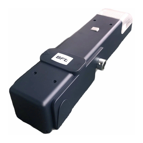
BFT ARGO BT A 20 User manual

D814081 03A79_01 27-06-19
ARGO BT A
20-35
INSTALLATION MANUAL
INSTRUCTIONS D’INSTALLATION
MONTAGEANLEITUNG
INSTALLATIEVOORSCHRIFTEN
INSTRUKCJA UŻYTKOWANIA I INSTALACJI
INÁVOD K OBSLUZE A INSTALACI
OPERATORS FOR INDUSTRIAL SECTIONAL DOORS
AUTOMATISMES POUR PORTES MULTI-LAMES INDUSTRIELLES
AUTOMATISCHE ANTRIEBE FÜR INDUSTRIE-SEKTIONALTORE
AUTOMATISERINGEN VOOR INDUSTRIËLE OPDRACHTGERICHTE DEUREN
AUTOMATY DO BRAM SEKCYJNYCH PRZEMYSŁOWYCH
AUTOMATICKÉ SYSTÉMY PRO PRŮMYSLOVÁ SEKČNÍ VRATA
Caution! Read “Warnings” inside carefully! Attention! Veuillez lire attentivement les Avertissements qui se trouvent à l’intérieur! Achtung! Bitte lesen Sie aufmerksam die „Hinweise“ im Inneren! Let op! Lees de “Waar-
schuwingen”aan de binnenkant zorgvuldig!Uwaga! Należy uważnie przeczytać “Ostrzeżenia”w środku! ! “”! Varování! Přečtěte si pozorně kapitolu
“Upozornění”!

GENERAL INFORMATION
Actuator for motorizing residential and industrial sectional doors. Its compact design and mounting versatility mean the drive can be applied in
dierent ways.
GÉNÉRALITÉS
Actionneur pour motorisation de portes résidentielles et industrielles. La compacité et la versatilité de montage permettent d’appliquer diérents
modes de motorisation.
ALLGEMEINES
Trieb für die Motorisierung von Sektionaltoren in Wohn- und Industriebauten. Die Kompaktheit und die Vielseitigkeit gestatten eine Vielzahl von
Einsatzweisen der Motorisierung.
ALGEMEENHEDEN
Aandrijver voor motorisering van de residentiële en industriële sectiedeuren. De compactheid en de veelzijdigheid van montage maken de mo-
torisering toepasselijk op verschillende manieren.
UWAGI OGÓLNE
Automat napędowy do bram sekcyjnych mieszkalnych i przemysłowych. Łatwość i zróżnicowane możliwości montażowe sprawiają, iż napęd
znajduje zastosowanie w przeróżnych kombinacjach.
, .
.
VŠEOBECNÉ ÚDAJE
Akční prvek pro motorový pohon sekčních vrat domovních a průmyslových.
Díky kompaktní a všestranné montáži lze motorový pohon použít různými
způsoby.
KIT COMPOSITION - COMPOSITION DU KIT
ZUSAMMENSETZUNG DES BAUSATZES - SAMENSTELLING VAN DE KIT
SKŁAD ZESTAWU - - SLOŽENÍ SADY
Ø16
Wall
Mural
Mauer
Muur
Ścianie
Стене
Zeď
EQUIPMENT- OUTILS - AUSRÜSTUNG-UITRUSTING - NARZĘDZIA - - VYBAVENÍ
17
PH2
PH2
For installations that require the operator to operate at heights greater than 2 meters above the oor level, it is mandatory to use equipment with higher safety levels such
as scaolding or rolling towers. For activities outside Italy, check the specic local legislation in advance.
Pour les installations qui exigent que l’opérateur travaille à des hauteurs supérieures à 2 mètres par rapport au plancher, utiliser impérativement des équipements avec des
niveaux de sécurité supérieurs tels qu’échafaudages ou chevalets. Pour les activités à l’étranger, consulter à l’avance les réglementations locales spéciques.
Für Installationen, bei denen in Höhen von über 2 Meter über dem darunterliegenden Boden gearbeitet werden muss, müssen Ausrüstungen mit erhöhtem Sicherheitsniveau verwendet
werden, wie zum Beispiel Maurerarbeitsbühnen oder fahrbare Gerüste. Überprüfen Sie bei Arbeiten außerhalb Italiens vorher die entsprechenden örtlichen Bestimmungen.
Voor installaties waarbij de operator op een hoogte van meer dan 2 meter boven het onderstaande niveau moet werken, is het verplicht uitrustingen te gebruiken met hogere
beveiligingsniveaus, zoals ladders of steigers. Voor activiteiten buiten Italië, moet men vooraf de specieke lokale normen controleren.
w instalacjach, które wymagają pracy operatora na wysokości większej niż 2 metry od podłoża, obowiązkowo należy stosować sprzęt o zwiększonym poziomie bezpieczeństwa,
taki jak np.rusztowanie lub rusztowania jezdne. Odnośnie działań prowadzonych poza terenem Włoch należy wcześniej sprawdzić przepisy obowiązujące w danym miejscu.
Для установок, эксплуатация которых предполагает, что оператор работать на высоте более 2 метров от находящегося под ним покрытия, необходимо
использовать средства, обеспечивающие более высокий уровень безопасности, такие как мостки или передвижные платформы. Перед выполнением работ
за пределами Италии следует предварительно ознакомиться с требованиями национального законодательства.
U zařízení, která vyžadují, aby provozovatel pracoval ve výškách více než 2 metry nad podlahou, je povinné používat vybavení s větším zabezpečením, jako je lešení nebo pra-
covní plošina. Pro činnosti mimo Itálii ověřte nejprve danou místní legislativu.
*
*
M10x20 GROWER
Ø10,5 Ø10,5
63.5
6.35
5.35
ISTRUZIONI D’USO E DI INSTALLAZIONE
INSTALLATION AND USER’S MANUAL
INSTRUCTIONS D’UTILISATION ET D’INSTALLATION
INSTALLATIONS-UND GEBRAUCHSANLEITUNG
INSTRUCCIONES DE USO Y DE INSTALACION
GEBRUIKS- EN INSTALLATIEAANWIJZINGEN
AUTOMAZIONIPER PORTE SEZIONALI INDUSTRIALI
OPERATORSFOR INDUSTRIAL SECTIONAL DOORS
AUTOMATISMESPOUR PORTES MULTI-LAMES INDUSTRIELLES
AUTOMATISCHEANTRIEBE FÜR INDUSTRIE-SEKTIONALTORE
AUTOMATISMOSPARA PUERTASSECCIONALES INDUSTRIALES
AUTOMATISERINGENVOOR INDUSTRIËLE OPDRACHTGERICHTE DEUREN
ARGO BT A
20-35
2-ARGO BT A 20-35
D814081 03A79_01

A
A1
B
115
351
65.5
292 59
226.5
77 19
22
M10
M10
377
*
230V
230V
240V
24V
880
*
Ø25.5(1 in)
11.5
101
CABLE ARRANGEMENT - PRÉDISPOSITION DES CÂBLES-VORBEREITUNG DER KABEL -PREDISPOSITIE KABELS
PRZYGOTOWANIE PRZEWODÓW- -PŘÍPRAVA KABELŮ
DIMENSIONS - DIMENSIONS -ABMESSUNGEN - AFMETINGEN - WYMIARY - -ROZMĚRY
CABLE ENTRY ENTRÉE CÂBLESKABELEINGAN
INGANG KABELS
WEJŚCIE KABLI-
-VSTUP KABELŮ
ARGO BT A 20-35 - 3
D814081 03A79_01

C
C1
65 min.
226
95 115
276
180 max
341 max
256
171
90
73
90
INSTALLATION MODE-MODE D’INSTALLATION-INSTALLATIONSMETHODE - INSTALLATIEMODUS
SPOSÓB INSTALACJI- -ZPŮSOB INSTALACE
MOTOR POSITIONS WITH STANDARD FASTENING BRACKET, POSITIONS DU MOTEUR AVEC BRIDE DE FIXATION DE SÉRIE,
MOTORPOSITIONEN MIT SERIENMÄSSIGEM BEFESTIGUNGSBÜGEL, POSITIES MOTOR MET STANDAARD BEVESTIGINGSBEUGEL
POŁOŻENIE SILNIKA ZE STANDARDOWYM UCHWYTEM MOCUJĄCYM,
, UMÍSTĚNÍ MOTORU SE STANDARDNÍM UPEVŇOVACÍM DRŽÁKEM
MOTOR POSITIONS WITH STANDARD FASTENING BRACKET AND NON-STANDARD ACCESSORY
POSITIONS DU MOTEUR AVEC BRIDE DE FIXATION DE SÉRIE ET ACCESSOIRE NON FOURNI DE SÉRIE
MOTORPOSITIONEN MIT SERIENMÄSSIGEM BEFESTIGUNGSBÜGEL UND NICHT MITGELIEFERTEM ZUBEHÖR
POSITIES MOTOR MET STANDAARD BEVESTIGINGSBEUGEL EN ACCESSOIRES NIET BIJGELEVERD
POŁOŻENIE SILNIKA ZE STANDARDOWYM UCHWYTEM MOCUJĄCYM I Z OSPRZĘTEM NIEWCHODZĄCYM W SKŁAD DOSTAWY
UMÍSTĚNÍ MOTORU SE STANDARDNÍM UPEVŇOVACÍM DRŽÁKEM A NESTANDARDNÍM PŘÍSLUŠENSTVÍM
right
droitea
rechts
lewa
vpravo
right
droitea
rechts
lewa
vpravo
left
gauche
links
wersja prawa
vlevo
left
gauche
links
wersja prawa
vlevo
TO OPEN
(OPEN IN OTHER DIRECT= OFF)
OUVERTURE
(INV.SENS.OUV= OFF)
ÖFFNUNG
(INV RICHT OFFNUNG= OFF)
OPENING
(OPENIN OTHER DIRECT.= OFF)
4-ARGO BT A 20-35
D814081 03A79_01

D
20
Ø10,5 Ø10,5
17
10
V1
R1 R2
V2
R1
R2
R2
Ø16
PH2
>115
>115
*
ASSEMBLY AND INSTALLATION-MONTAGE ET INSTALLATION-MONTAGE UND INSTALLATION
MONTAGE EN INSTALLATIE-MONTAŻ I INSTALACJA- - MONTÁŽ A INSTALACE
Loosen without dismantling!
Desserrer sans enlever!
Lösen, aber nicht entfernen!
Lossen zonder te verwijderen!
Poluzować, ale nie wyjmować!
, !
Uvolněte bez odstranění!
Not supplied
Ne sont pas fournis
Nicht im lieferum
Niet meegeleverd
Nie dostarczane w zestawie
Není součástí dodávky
Wall
Mural
Mauer
Muur
Ścianie
Стене
Zeď
ARGO BT A 20-35 - 5
D814081 03A79_01

Ø 16mm
D
V1
R1
R2
20
Ø10,5 Ø10,5
10
V1
R1 R2
2
R2
R2
V1 R1
Not supplied
Ne sont pas fournis
Nicht im lieferum
Niet meegeleverd
Nie dostarczane w zestawie
Není součástí dodávky
Fix!
Fixer! Reparieren!
Repareren!
Przymocować!
! Opravit!
6-ARGO BT A 20-35
D814081 03A79_01

. . . . . .
KO
>30 s
KO
>30 s
KO
>30 s
KO
>30 s
KO
>30 s
KO
>30 s
. . . . . .
. . . . . .
OK
. . . . . .
. . . . . .
. . . . . .
H
E
KO
. . . . . .
PUTTING INTO OPERATION FROM GROUND-MISE EN MARCHE DEPUIS LE SOL-INBETRIEBNAHME VOM BODEN
INBEDRIJFSTELLING VANAF DE GROND-URUCHOMIENIE ZE STANOWISKA NA ZIEMI-
-UVEDENÍ DO PROVOZU ZE ZEMĚ
Function activated automatically only if the settings are the factory settings (default) and no remote control is memorized
Fonction activée automatiquement uniquement si les réglages sont les réglages d’usine (par défaut) et sans télécommande mémorisée
Die Funktion wird nur automatisch aktiviert, wenn die Werkseinstellungen (Default) eingestellt sind und keine Funksteuerung gespeichert ist
Functie enkel automatisch ingeschakeld als de (standaard) fabrieksinstellingen actief zijn en er geen afstandsbediening opgeslagen is
Funkcja aktywowana automatycznie tylko w przypadku ustawień fabrycznych (domyślnych) i bez żadnego zapamiętanego pilota
, ( ) .
Funkce se aktivuje automaticky pouze v případě, že se jedná o nastavení v závodu (výchozí nastavení) a žádné rádiové ovládání není uloženo v paměti
Mount the operator with door partially closed.
Monter l’opérateur avec la porte partiellement fermée.
Den Antrieb bei teilweise geschlossener Tür montieren.
Monteer de operator wanneer de poort gedeeltelijk is gesloten.
Siłownik zamontować przy częściowo zamkniętych drzwiach.
.
Namontujte pohon s částečně zavřenými dveřmi.
ARGO BT A 20-35 - 7
D814081 03A79_01

WARNING!! Check that the force of impact measured at the points provided for by standard EN 12445 is lower than the value laid down by standard
EN 12453.
Warning!! While the autoset function is running, the obstacle detection function is not active. Consequently, the installer must monitor the automated
system’s movements and keep people and property out of range of the automated system.
ATTENTION !! Vériez si la valeur de la force de choc mesurée dans les points prévus par la norme EN12445 est inférieure à celle indiquée dans la
norme EN 12453.
Attention !! Pendant l’autoréglage la fonction de détection des obstacles n’étant pas active le monteur doit contrôler le mouvement de l’automatisation
et empêcher que des personnes ou des choses ne s’approchent ou ne stationnent dans le rayon d’action de l’automatisation.
ACHTUNG!! Stellen Sie sicher, dass der Wert der Kraft, gemessen an den gemäß Norm EN12445 vorgesehenen Punkten, kleiner als der in der Norm
EN 12453 angegeben ist.
Achtung!! Während der Auto-Einstellung ist die Funktion Hinderniserfassung nicht aktiv; der Monteur muss die Bewegung der Automatisierung über-
wachen und verhindern, dass Personen oder Sachen in den Bewegungsbereich der Automatisierung gelangen.
OPGELET!! Controleren of de waarde van de botsingskracht gemeten in de punten voorzien door de norm EN12445, lager is dan hetgeen aange-
geven in de norm EN 12453.
Opgelet!! Tijdens de autoset-fase is de functie voor obstakeldetectie niet actief; de installateur moet de beweging van het automatiseringssysteem con-
trolerenen voorkomen dat personen ofvoorwerpenin de buurt komen vandeactieradius van het automatiseringssysteem ofzichdaarbinnen bevinden.
UWAGA!! Sprawdzić, czy wartość siły uderzenia zmierzona w miejscach przewidzianych w normie EN12445 jest mniejsza niż podano w normie EN 12453.
Uwaga!! Podczas automatycznego ustawiania funkcja wykrywania przeszkód jest nieaktywna; instalator powinien kontrolować ruch automatu i
pilnować, aby żadne osoby nie zbliżały się do obszaru roboczego automatu, oraz aby w tym obszarze nie znajdowały się żadne przedmioty.
! , , , EN12445,
EN 12453.
!! ,
.
Podle normy EN 12445, je menší, než je uvedeno v normě EN 12453.
Pozor!! Během automatického nastavení není funkce zjišťování překážek aktivní, instalatér tedy musí kontrolovat pohyb automatického systému
a zabránit osobám nebo věcem přiblížit se nebo prodlévat v akčním rádiu automatického systému.
8-ARGO BT A 20-35
D814081 03A79_01

H
F
24V~(-)
24V~(+)
24 VSafe~(+)
IC 1
IC 2
NO
NO
SAFE 1
STOP
COM
SAFE 2
NC
NC
NC
AUX 3
(MAX 24V 1A)
20 2126 27 70 7172 7350 515260 6162
20 2126 27 70 7172 7350 515260 6162
Courtesy lamp,
Lampe de courtoisie,
Hilfsbeleuchtung,
Luz interior, Waaklicht,
Oświetlenie wnętrza,
,
Prodleva zhasnutí
Palmtop programmer connector,
Connecteur programmateur de poche,
Steckverbinder Palmtop-Programmierer,
Connector programmeerbare palmtop.
Łącznik programatora cyfrowego,
,
Konektor ručního programátoru
Display plus programming keys,
Acheur et touches de programmation,
Display und Programmierungstasten,
Display meerdere toetsen programmeur.
Wyświetlacz + przyciski programowania,
+ ,
Displej + programovací tlačítka
Power ON LED,
Voyant LED présence d’alimentation,
Led Vorhandensein Stromversorgung
Led Aanwezigheid voeding
Kontrolka zasilania
Kontrolka LED přítomnosti napětí
Optional board connector,
Connecteur carte facultative,
Steckverbinder Zusatzkarte,
Connector optionele kaart.
Łącznik karty opcjonalnej,
,
Konektor doplňkové přídavné karty
Fuse,
Fusible,
Schmelzsicherung,
Zekering
Bezpiecznik,
,
Pojistka:
1,6 AT
ARGO BT A 20-35 - 9
D814081 03A79_01

ENGLISH
Terminal Denition Description
Aux
20
AUX 0 - 24V POWE-
RED CONTACT (N.O.)
(MAX. 1A)
FLASHING LIGHT output .
The contact remains closed during the movement of the leaves.
21
26 AUX 3 - FREE
CONTACT (N.O.)
(MAX. 24V 1A)
AUX 3 congurable output - Default setting MONOSTABLE RADIO CHANNEL
Output MONOSTABLE RADIO CHANNEL/ SCA GATE OPEN LIGHT/ COURTESY LIGHT command/ ZONE LIGHT command/
STAIRLIGHT/GATEOPENALARM/FLASHINGLIGHT/SOLENOIDLATCH/MAGNETICLOCK/MAINTENANCE/FLASHINGLIGHT
AND MAINTENANCE / GATE CLOSED STATUS / BISTABLE RADIO CHANNEL /TIMED RADIO CHANNEL / GATE OPEN STATUS
27
Accessories
power
supply
50 24V- Accessories power supply output.
51 24V+
52 24 Vsafe+ Tested safety device power supply output (photocell transmitter).
Output active only during operating cycle.
Commands
60 Common IC 1 and IC 2 inputs common
61 IC 1 Congurable command input 1 (N.O.) - Default START E.
START E / START I / OPEN / CLOSE / PED / TIMER / TIMER PED
Refer to the“Command input conguration” table.
62 IC 2 Congurable command input 2 (N.O.) - Default PED.
START E / START I / OPEN / CLOSE / PED / TIMER / TIMER PED
Refer to the“Command input conguration” table.
Safety devices
70 Common STOP, SAFE 1 and SAFE 2 inputs common
71 STOP The command stops movement. (N.C.)
If not used, leave jumper inserted.
72 SAFE 1
Congurable safety input 1 (N.C.) - Default BAR.
PHOT / PHOT TEST / PHOT OP / PHOT OP TEST / PHOT CL / PHOT CL TEST / BAR / BAR TEST / BAR 8K2 /
BAR OP / BAR
OP TEST / BAR 8K2 OP/ BAR CL / BAR CL TEST / BAR 8K2 CL /STOP 8K2
Refer to the“Safety input conguration” table.
73 SAFE 2
Congurable safety input 2 (N.C.) - Default PHOT.
PHOT / PHOT TEST / PHOT OP / PHOT OP TEST / PHOT CL / PHOT CL TEST / BAR / BAR TEST / BAR OP / BAR OP TEST / BAR CL /
BAR CL TEST
Refer to the“Safety input conguration” table.
FRANÇAIS
Borne Dénition Description
Aux
20 AUX 0 - CONTACT
ALIMENTÉ 24V
(N.O.) (1 A MAX)
Sortie pour CLIGNOTANT.
Le contact reste fermé pendant le mouvement des vantaux.
21
26 AUX 3 - CONTACT
LIBRE (N.O.)
(Max 24V 1A)
Sortie congurable AUX3 – Défaut Sortie 2ème CANAL RADIO.
CANAL RADIO MONOSTABLE/ VOYANT PORTAIL OUVERT SCA/ Commande LUMIÈRE COURTOISIE/ Commande LUMIÈRE
ZONE/ LUMIÈRE ESCALIERS/ ALARME PORTAIL OUVERT/ CLIGNOTANT/ SERRURE ÉLECTRIQUE À DÉCLIC/ SERRURE ÉLECTRI-
QUE À AIMANT/ENTRETIEN/CLIGNOTANT ET ENTRETIEN / ANTIEFFRACTION/ ETAT PORTAIL FERME’/CANAL RADIO BISTABLE/
CANAL RADIO TEMPORISE/ ETAT PORTAIL OUVERT
27
Alimentation
des
accessoires
50 24V- Sortie alimentation accessoires.
51 24V+
52 24 Vsafe+ Sortie alimentation des dispositifs de sécurité vériés (émetteur photocellules)
Sortie active uniquement pendant le cycle de manœuvre.
Commandes
60 Commun Commun entrées IC 1 et IC 2
61 IC 1 Entrée de commande congurable 1 (N.O.) - Défaut START E.
START E / START I / OPEN / CLOSE / PED / TIMER / TIMER PED
Consulter le tableau“Conguration des entrées de commande”.
62 IC 2 Entrée de commande congurable 2 (N.O.) - Défaut PED.
START E / START I / OPEN / CLOSE / PED / TIMER / TIMER PED
Consulter le tableau“Conguration des entrées de commande”.
Sécurités
70 Commun Commun entrées STOP, SAFE 1 et SAFE 2
71 STOP La commande interrompt la manœuvre. (N.F.)
Si vous ne l’utilisez pas, laissez la barrette en place.
72 SAFE 1
Entrée de sécurité congurable 1 (N.F.) - Défaut BAR.
PHOT / PHOT TEST / PHOT OP / PHOT OP TEST / PHOT CL / PHOT CL TEST / BAR / BAR TEST / BAR 8K2 /
BAR OP / BAR
OP TEST / BAR 8K2 OP/ BAR CL / BAR CL TEST / BAR 8K2 CL /STOP 8K2
Consulter le tableau“Conguration des entrées de sécurité”.
73 SAFE 2
Entrée de sécurité congurable 2 (N.C.) - Défaut PHOT.
PHOT / PHOT TEST / PHOT OP / PHOT OP TEST / PHOT CL / PHOT CL TEST / BAR / BAR TEST / BAR OP / BAR OP TEST / BAR CL /
BAR CL TEST
Consulter le tableau“Conguration des entrées de sécurité”.
DEUTSCH
Klemme Denition Beschreibung
Aux
20 BLINKEND -
GESPEISTER
KONTAKT 24V
(N.O.) (1A MAX)
BLINKENDER Ausgang.
Der Kontakt bleibt während der Bewegung der Türügel geschlossen.
21
26 AUX 3 - FREIER
KONTAKT (N.O.)
(Max 24V 1A)
Kongurierbarer Ausgang AUX 3 - Default Ausgang 2. FUNKKANAL.
2. FUNKKANAL/ KONTROLLLEUCHTE TOR OFFEN SCA/ Steuerung INNENLEUCHTE/ Steuerung BEREICHSLICHT/
TREPPENLEUCHTE / ALARM TOR OFFEN/ BLINKEND/ ELEKTRO-VERSCHLUSS MIT EINRASTEN/ ELEKTRO-VERSCHLUSS
MIT MAGNET / WARTUNG / BLINKEND / WARTUNG / EINBRUCHSSCHUTZ / STATUS TOR GESCHLOSSEN / BISTABILER
FUNKKANAL / ZEITGESTEUERTER FUNKKANAL / STATUS TOR OFFEN
27
Strom-
vers.
Zubehör
50 24V- Ausgang Stromversorgung Zubehör.
51 24V+
52 24 Vsafe+
Stromversorgungsausgang für geprüfte Sicherheitsvorrichtungen (Fotozellensender).
Ausgang nur während des Manöverzyklus aktiv.
Befehle
60 Sammel Sammeleingänge IC 1 und IC 2
61 IC 1 Kongurierbarer Steuereingang 1 (N.O.) - Default START E.
START E / START I / OFFEN / GESCHLOSSEN / PED / TIMER / TIMER PED
Siehe Tabelle“Konguration der Steuereingänge”.
62 IC 2 Kongurierbarer Steuereingang 2 (N.O.) - Default PED.
START E / START I / OFFEN / GESCHLOSSEN / PED / TIMER / TIMER PED
Siehe Tabelle“Konguration der Steuereingänge”.
Sicherheit
70 Sammel Sammeleingänge STOP, SAFE 1 und SAFE 2
71 STOP Der Befehl unterbricht das Manöver. (N.C.)
Wenn nicht verwendet, die Überbrückung eingeschaltet lassen.
72 SAFE 1
Kongurierbarer Sicherheitseingang 1 (N.C.) - Default BAR.
PHOT / PHOT TEST / PHOT OP / PHOT OP TEST / PHOT CL / PHOT CL TEST / BAR / BAR TEST / BAR 8K2 / BAR OP /
BAR OP TEST / BAR 8K2 OP/ BAR CL / BAR CL TEST / BAR 8K2 CL /STOP 8K2
Siehe Tabelle“Konguration der Sicherheitseingänge”.
73 SAFE 2
Kongurierbarer Sicherheitseingang 2 (N.C.) - Default PHOT.
PHOT / PHOT TEST / PHOT OP / PHOT OP TEST / PHOT CL / PHOT CL TEST / BAR / BAR TEST / BAR OP / BAR OP TEST / BAR
CL / BAR CL TEST
Siehe Tabelle“Konguration der Sicherheitseingänge”.
10-ARGO BT A 20-35
D814081 03A79_01
NEDERLANDS
Klem Denitie Beschrijving
Aux
20 KNIPPERLICHT -
CONTACT GEVOED
24V (N.O.) (1A
MAX)
Uitgang KNIPPERLICHT.
Het contact blijft gesloten tijdens de beweging van de vleugels.
21
26 AUX 3 - VRIJ CON-
TACT (N.O.)
(Max 24V 1A)
Congureerbare AUX 3 - Standaard Uitgang 2° RADIOKANAAL.
2° RADIOKANAAL/ CONTROLELAMP POORT GEOPEND SCA/ Bediening VERLICHTING/ Bediening LICHT ZONE/
LICHT TRAPPEN/ ALARM POORT GEOPEND/ KNIPPERLICHT/ ELEKTRISCH SNAPSLOT/ ELEKTRISCH MAGNEETSLOT /
ONDERHOUD/ KNIPPERLICHT/ ONDERHOUD /INBRAAKBEVEILIGING/ STATUS POORT GESLOTEN/ BISTABIEL RADIO-
KANAAL/ RADIOKANAAL MET TIMER/ STATUS POORT GEOPEND
27
Toev.
Acces-
soires
50 24V- Uitgang toevoer accessoires.
51 24V+
52 24 Vsafe+
Uitgang voeding voor geverieerde veiligheidsvoorzieningen (zender fotocellen).
Uitgang enkel actief tijdens de bewegingscyclus.
Bedieningen
60 Gemeenschappelijk Gemeenschappelijk ingangen IC 1 en IC 2
61 IC 1 Congureerbare ingang bediening 1 (N.O.) - Standaard START E.
START E / START I / OPEN / CLOSE / PED / TIMER / TIMER PED
Zie de tabel“Conguratie ingangen bediening”.
62 IC 2 Congureerbare ingang bediening 2 (N.O.) - Standaard PED.
START E / START I / OPEN / CLOSE / PED / TIMER / TIMER PED
Zie de tabel“Conguratie ingangen bediening”.
Beveiligingen
70 Gemeenschappelijk Gemeenschappelijk ingangen STOP, SAFE 1 en SAFE 2
71 STOP Het commando onderbreekt de beweging. (N.C.)
Laat de brug verbonden indien ze niet gebruikt wordt.
72 SAFE 1
Congureerbare ingang veiligheid 1 (N.C.) - Standaard BAR.
PHOT / PHOT TEST / PHOT OP / PHOT OP TEST / PHOT CL / PHOT CL TEST / BAR / BAR TEST / BAR 8K2 / BAR OP /
BAR OP TEST / BAR 8K2 OP/ BAR CL / BAR CL TEST / BAR 8K2 CL /STOP 8K2
Zie de tabel“Conguratie ingangen veiligheid”.
73 SAFE 2
Congureerbare ingang veiligheid 2 (N.C.) - Standaard PHOT.
PHOT / PHOT TEST / PHOT OP / PHOT OP TEST / PHOT CL / PHOT CL TEST / BAR / BAR TEST / BAR OP / BAR OP TEST / BAR
CL / BAR CL TEST
Zie de tabel“Conguratie ingangen veiligheid”.
POLSKI
Zacisk Nazwa Opis
Aux
20 LAMPA MIGAJĄCA
- STYK ZASILANY
24 V (N.O.)
(1A MAKS.)
Wyjście LAMPY MIGAJĄCEJ
Styk pozostaje zamknięty podczas ruchu skrzydeł.
21
26 AUX 3 - STYK
WOLNY (N.O.)
(Maks. 24V 1A)
Wyjście kongurowalne AUX 3 - Default Wyjście 2. KANAŁ RADIA.
2.KANAŁRADIA/ KONTROLKABRAMAOTWARTA SCA/SterowanieŚWIATŁEMZEWNĘTRZNYM/SterowanieŚWIATŁEM
STREFY/ ŚWIATŁEM SCHODÓW/ ALARM DRZWI BRAMY OTWARTEJ/ MIGAJĄCY/ ELEKTROZAMEK ZATRZASKOWY/
ELEKTROZAMEKMAGNETYCZNY/KONSERWACJA/MIGAJĄCY/KONSERWACJA/PRZECIWWŁAMANIOWY/STANBRAMY
ZAMKNIĘTEJ/ KANAŁ RADIA BISTABILNY / KANAŁ RADIA CZASOWY/ STAN BRAMY OTWARTEJ
27
Zasil.
Akce-
soria
50 24V- Wyjście zasilania akcesoriów.
51 24V+
52 24 Vsafe+
Wyjście zasilania dla zwerykowanych urządzeń bezpieczeństwa (nadajnik fotokomórek).
Wyjście aktywne tylko podczas wykonywania cyklu.
Przyciski ste-
rownicze
60 Wspólny Wspólny wejść IC 1 i IC 2
61 IC 1 Wejście sterowania kongurowalne 1 (N.O.) - Default START E.
START E / START I / OPEN / CLOSE / PED / TIMER / TIMER PED
Odnieść się do tabeli„Konguracja wejść sterowania”.
62 IC 2 Wejście sterowania kongurowalne 2 (N.O.) - Default PED.
START E / START I / OPEN / CLOSE / PED / TIMER / TIMER PED
Odnieść się do tabeli„Konguracja wejść sterowania”.
Zabezpie
czenia
70 Wspólny Wspólny wejść STOP, SAFE 1 i SAFE 2
71 STOP Polecenie przerywa manewr. (N.Z.)
Jeśli nie jest używane, zostawić mostek założony.
72 SAFE 1
Wejście bezpieczeństwa kongurowalne 1 (N.Z.) - Default BAR.
PHOT / PHOT TEST / PHOT OP / PHOT OP TEST / PHOT CL / PHOT CL TEST / BAR / BAR TEST / BAR 8K2 / BAR OP / BAR OP
TEST / BAR 8K2 OP/ BAR CL / BAR CL TEST / BAR 8K2 CL /STOP 8K2
Odnieść się do tabeli„Konguracja wejść bezpieczeństwa”.
73 SAFE 2
Wejście bezpieczeństwa kongurowalne 2 (N.Z.) - Default PHOT.
PHOT / PHOT TEST / PHOT OP / PHOT OP TEST / PHOT CL / PHOT CL TEST / BAR / BAR TEST / BAR OP / BAR OP TEST /
BAR CL / BAR CL TEST
Odnieść się do tabeli„Konguracja wejść bezpieczeństwa”.
PCCK
Aux
20 -
24
(..) ( 1 )
.
.
21
26 . 3 -
(..)
(Ma. 24 1A)
.3 - 2° .
2° / SCA/ /
/ / / /
/ / / / /
//
/ /
27
.
.
50 24V- Saída de alimentação dos acessórios.
51 24V+
52 24 . +
( ).
.
60 . IC 1 IC 2
61 IC 1 1 (..) - START E.
START E / START I / OPEN / CLOSE / PED / TIMER / TIMER PED
.“ ”.
62 IC 2 2 (..) - PED.
START E / START I / OPEN / CLOSE / PED / TIMER / TIMER PED
.“ ”.
70 . STOP, SAFE 1 SAFE 2
71 STOP . (..)
, .
72 SAFE 1
1 (..) - BAR.
PHOT / PHOT TEST / PHOT OP / PHOT OP TEST / PHOT CL / PHOT CL TEST / BAR / BARTEST / BAR 8K2 / BAR OP / BAR
OP TEST / BAR 8K2 OP/ BAR CL / BAR CL TEST / BAR 8K2 CL /STOP 8K2
.“ ”.
73 SAFE 2
2 (..) - PHOT.
PHOT / PHOT TEST / PHOT OP / PHOT OP TEST / PHOT CL / PHOT CL TEST / BAR / BARTEST / BAR OP / BAR OP TEST
/ BAR CL / BAR CL TEST
.“ ”.
ARGO BT A 20-35 - 11
D814081 03A79_01

1
2
1
2
H
G
18
2
3
4
5
6
7
5s
20 2126 27 70 7172 7350 515260 6162
70 7172 7360 6162
9
OK
20 2126 27 70 7172 7350 515260 6162
OK
20 2126 27 70 7172 7350 515260 6162
OK
20 2126 27 70 7172 7350 515260 6162
OK
20 2126 27 70 7172 7350 515260 6162
OK
20 2126 27 70 7172 7350 515260 6162
20 2126 27 70 7172 7350 515260 6162
OK
20 2126 27 70 7172 7350 515260 6162
OK
12
13
10
11
20 2126 27 70 7172 7350 515260 6162
a.prg
20 2126 27 70 7172 7350 515260 6162
autoset
20 2126 27 70 7172 7350 515260 6162
close
20 2126 27 70 7172 7350 515260 6162
open
20 2126 27 70 7172 7350 515260 6162
prg
20 2126 27 70 7172 7350 515260 6162
up
20 2126 27 70 7172 7350 515260 6162
20 2126 27 70 7172 7350 515260 6162
prg
20 2126 27 70 7172 7350 515260 6162
down
20 2126 27 70 7172 7350 515260 6162
. . . .
20 2126 27 70 7172 7350 515260 6162
. . . .
20 2126 27 70 7172 7350 515260 6162
. . . .
20 2126 27 70 7172 7350 515260 6162
. . . .
20 2126 27 70 7172 7350 515260 6162
20 2126 27 70 7172 7350 515260 6162
20 2126 27 70 7172 7350 515260 6162
OK
20 2126 27 70 7172 7350 515260 6162
20 2126 27 70 7172 7350 515260 6162
20 2126 27 70 7172 7350 515260 6162
ČEŠTINA
Svorka Popis POPIS
Aux
20 BLIKAJÍCÍ - STYKAČ
NAPÁJENÍ 24V (N.O.)
(1A MAX)
BLIKAJÍCÍ výstup.
Kontakt zůstane sepnutý během pohybu brány.
21
26
AUX 3 – VOLNÝ KON-
TAKT (N.O.)
(Max. 24 V 1 A)
Kongurovatelný výstup AUX 3 – defaultní nastavení výstupu 2. KANÁLU RÁDIA.
2.KANÁLRÁDIA/KONTROLKAOTEVŘENÝCHVRATSCA/OvládáníDISKRÉTNÍHOOSVĚTLENÍ/OvládáníZÓNOVÉHO
OSVĚTLENÍ / OSVĚTLENÍ SCHODŮ / VÝSTRAŽNÉ UPOZORNĚNÍ NA OTEVŘENÁ VRATA / BLIKAJÍCÍ / IMPULZNÍ
ELEKTRICKÉZAMYKÁNÍ/ELEKTROMAGNETICKÉZAMYKÁNÍ/BLIKAJÍCÍ/ÚDRŽBA/SYSTÉMPROTINEOPRÁVNĚNÝM
ZÁSAHŮM / STAV ZAVŘENÝCH VRAT / RÁDIOVÝ KANÁL S BISTABILNÍM REŽIMEM / RÁDIOVÝ KANÁL S REŽIMEM
ČASOVÁNÍ / STAV OTEVŘENÝCH VRAT
27
Napáj.
Přísluše
nství
50 24V- Výstup napájení příslušenství.
51 24V+
52 24 Vsafe+
Výstup napájení pro ověřená bezpečnostní zařízení (vysílač fotobuněk).
Výstup je aktivní pouze během manévrování.
Ovladače
60 Všeobecný Všeobecný vstupy IC 1 a IC 2
61 IC 1 Kongurovatelný ovládací vstup 1 (N.O.) – defaultní START E.
START E / START I / OPEN (otevření) / CLOSE (zavření) / PED / TIMER (časovač) / TIMER PED
Seznamte se s tabulkou„Kongurace ovládacích vstupů“.
62 IC 2 Kongurovatelný ovládací vstup 2 (N.O.) – defaultní PED.
START E / START I / OPEN (otevření) / CLOSE (zavření) / PED / TIMER (časovač) / TIMER PED
Seznamte se s tabulkou„Kongurace ovládacích vstupů“.
Zabezpečení
70 Všeobecný Všeobecný vstupy STOP, SAFE 1 a SAFE 2
71 STOP Ovladač přeruší manévr. (N.C.)
Pokud se nepoužívá, nechte drát zapojený.
72 SAFE 1
Kongurovatelný bezpečnostní vstup 1 (N.C.) – defaultní BAR.
PHOT / PHOT TEST / PHOT OP / PHOT OP TEST / PHOT CL / PHOT CL TEST / BAR / BAR TEST / BAR 8K2 / BAR OP /
BAR OP TEST / BAR 8K2 OP / BAR CL / BAR CL TEST / BAR 8K2 CL / STOP 8K2
Seznamte se s tabulkou„Kongurace bezpečnostních ovládacích vstupů“.
73 SAFE 2
Kongurovatelný bezpečnostní vstup 2 (N.C.) – defaultní PHOT.
PHOT / PHOT TEST / PHOT OP / PHOT OP TEST / PHOT CL / PHOT CL TEST / BAR / BAR TEST / BAR OP / BAR OP TEST / BAR
CL / BAR CL TEST
Seznamte se s tabulkou„Kongurace bezpečnostních ovládacích vstupů“.
12-ARGO BT A 20-35
D814081 03A79_01

1
2
1
2
H
G
18
2
3
4
5
6
7
5s
20 2126 27 70 7172 7350 515260 6162
70 7172 7360 6162
9
OK
20 2126 27 70 7172 7350 515260 6162
OK
20 2126 27 70 7172 7350 515260 6162
OK
20 2126 27 70 7172 7350 515260 6162
OK
20 2126 27 70 7172 7350 515260 6162
OK
20 2126 27 70 7172 7350 515260 6162
20 2126 27 70 7172 7350 515260 6162
OK
20 2126 27 70 7172 7350 515260 6162
OK
12
13
10
11
20 2126 27 70 7172 7350 515260 6162
a.prg
20 2126 27 70 7172 7350 515260 6162
autoset
20 2126 27 70 7172 7350 515260 6162
close
20 2126 27 70 7172 7350 515260 6162
open
20 2126 27 70 7172 7350 515260 6162
prg
20 2126 27 70 7172 7350 515260 6162
up
20 2126 27 70 7172 7350 515260 6162
20 2126 27 70 7172 7350 515260 6162
prg
20 2126 27 70 7172 7350 515260 6162
down
20 2126 27 70 7172 7350 515260 6162
. . . .
20 2126 27 70 7172 7350 515260 6162
. . . .
20 2126 27 70 7172 7350 515260 6162
. . . .
20 2126 27 70 7172 7350 515260 6162
. . . .
20 2126 27 70 7172 7350 515260 6162
20 2126 27 70 7172 7350 515260 6162
20 2126 27 70 7172 7350 515260 6162
OK
20 2126 27 70 7172 7350 515260 6162
20 2126 27 70 7172 7350 515260 6162
20 2126 27 70 7172 7350 515260 6162
START-UP - MISE EN SERVICE - INBETRIEBNAHME - INBEDRIJFSTELLING- URUCHAMIANIE- - ΘΕΣΗ ΣΕ ΛΕΙΤΟΥΡΓΙΑ
ARGO BT A 20-35 - 13
D814081 03A79_01

WARNING!! Check that the force of impact measured at the points provided for by standard EN 12445 is lower than the value laid
down by standard EN 12453.
Warning!! While the autoset function is running, the obstacle detection function is not active. Consequently, the installer must monitor
the automated system’s movements and keep people and property out of range of the automated system.
ATTENTION !! Vériez si la valeur de la force de choc mesurée dans les points prévus par la norme EN12445 est inférieure à celle
indiquée dans la norme EN 12453.
Attention !! Pendant l’autoréglage la fonction de détection des obstacles n’étant pas active le monteur doit contrôler le mouvement de
l’automatisationetempêcherquedespersonnesoudeschosesnes’approchentounestationnentdanslerayond’actiondel’automatisation.
ACHTUNG!! Stellen Sie sicher, dass der Wert der Kraft, gemessen an den gemäß Norm EN12445 vorgesehenen Punkten, kleiner als
der in der Norm EN 12453 angegeben ist.
Achtung!! Während der Auto-Einstellung ist die Funktion Hinderniserfassung nicht aktiv; der Monteur muss die Bewegung der Automa-
tisierung überwachen und verhindern, dass Personen oder Sachen in den Bewegungsbereich der Automatisierung gelangen.
στα σηεία τα οποία ορίζει το πρότυπο EN12445, είναι κατώτερη από την τιή που προβλέπει το πρότυπο EN 12453.
Προσοχή!! Κατά τη διάρκεια τη αυτορρύθιση η λειτουργία ανίχνευση εποδίων δεν είναι ενεργή. Ο εγκαταστάτη πρέπει να
ελέγχειτην κίνησητουαυτοατισούκαιναηνεπιτρέπεισε κανένανναπλησιάσειή να σταθείεντότηακτίνα δράση τουηχανισού.
UWAGA!!Sprawdzić,czy wartośćsiłyuderzenia zmierzonawmiejscach przewidzianychw normie EN12445jest mniejszaniż podanow normie
EN 12453.
Uwaga!! Podczas automatycznego ustawiania funkcja wykrywania przeszkód jest nieaktywna; instalator powinien kontrolować ruch
automatu i pilnować, aby żadne osoby nie zbliżały się do obszaru roboczego automatu, oraz aby w tym obszarze nie znajdowały się
żadne przedmioty.
! , , , EN12445,
EN 12453.
!! ,
.
Podle normy EN 12445, je menší, než je uvedeno v normě EN 12453 .
Pozor!! Během automatického nastavení není funkce zjišťování překážek aktivní, instalatér tedy musí kontrolovat pohyb automa-
tického systému a zabránit osobám nebo věcem přiblížit se nebo prodlévat v akčním rádiu automatického systému.
14-ARGO BT A 20-35
D814081 03A79_01

H
K
H
L
H
J
H
I
o o o
<10 s
prg
<10 s
o o o
<10 s <10 s
1
1 3
4 5 6
2
2 3 4 5 6 7
10 s 10 s
o o
o o
OK
<3s
+
70 7172 7350 515260 6162
20 2126 27 70 7172 7350 515260 6162
5s
20 2126 27 70 7172 7350 515260 6162
20 2126 27 70 7172 7350 515260 6162
20 2126 27 70 7172 7350 515260 6162
20 2126 27 70 7172 7350 515260 6162
20 2126 27 70 7172 7350 515260 6162
8888
8888
. . . .
rst
2s
2s
*
*
*DEFAULT
70 71
TRANSMITTERS CANCELLATION ANNULATION DES ÉMETTEURSLÖSCHEN DER SENDER WISSEN ZENDERS
ANNULATION DES ÉMETTEURSLÖSCHEN DER SENDER ELIMINACIÓN TRANSMISORES
REMOTE TRANSMITTER PROGRAMMING PROGRAMMATION ÉMETTEURS À DISTANCE FERNPROGRAMMIERUNG DER SENDER
PROGRAMMERING ZENDERS OP AFSTAND ZDALNE PROGRAMOWANIE NADAJNIKÓW
VZDÁLENÉ PROGRAMOVÁNÍ VYSÍLAČŮ
transmitter already memorized
émetteur déjà mémorisé
Sender bereits gespeichert
Sender zu speichern
Nadajnik zaprogramowany
Vysílač je již uložený v paměti
transmitter to be memorized
Émetteur à mémoriser
Reeds opgeslagen zender
Zender die opgeslagen moet worden
Nadajnik do programowania
Je nutné uložit vysílač do paměti
RESTORING FACTORY SETTINGS-RÉTABLISSEMENT DES CONFIGURATIONS D’USINE
-
WIDERHERSTELLUNG DER WERKSEINSTELLUNG-DE
FABRIEKSINSTELLINGEN HERSTELLEN-
RESETOWANIE DO USTAWIEŃ FABRYCZNYCH - -OBNO-
VENÍ TOVÁRNÍHO NASTAVENÍ
Cancellation in progress
Annulation en cours
Löschen läuft
Löschen durchgeführt
Kasowanie w toku
Probíhá mazání
Cancellation completed
Annulation eectuée
Wissen bezig
Wissen uitgevoerd
Kasowanie wykonane
Mazání dokončeno
MANUAL TRANSMITTER PROGRAMMING -PROGRAMMATION MANUELLE ÉMETTEURS-MANUELLE SENDERPROGRAMMIERUNG-HANDMATIGE PRO-
GRAMMERING ZENDERS -RĘCZNEPROGRAMOWANIENADAJNIKÓW- - RUČNÍ PROGRAMOVÁNÍVYSÍLAČŮ
PARTIAL OPENING
ouv.partielle
teilöffnung
ARGO BT A 20-35 - 15
D814081 03A79_01

ENGLISH
ACCESS MENUS Fig. 2
stat
password
-+
-+
OK
vers
bft . . .
+/-
OK
0000
+/-
+/-
n. cycles
OK
OK
01.33
0--- 10-- 150- 1520 prg
00
-+
err
02.01
........
30.15
+/-
Exit Menù
Conrm/Switch on display
Scroll up
Scroll down
See PARAMETERS MENU
See LOGIC MENU
language
n. remotes
List of last 30 errors
Control unit
software version
No total manoeuvres(in hundreds)
No radio controldevices memorised
x2
0--- 10-- 150- 1520 ok
***
See RADIO MENU
hidden butt
release desired button
Add. 2ch
hidden butt
release desired button
hidden butt
release desired button
Add. 4ch
hidden butt
release desired button
Add. 1ch
Add. 3ch
erase 64
If cancelled
If not present
If clone, it is disabled
(0001 )
ok
KO
dis
erase 1
*** Password entry.
Request with Protection Level
logic set to 1, 2, 3, 4
20 2126 27 70 7172 7350 515260 6162
8888
20 2126 27 70 7172 7350 515260 6162
8888
autoset
reg fc
Fig. G
phases 8 --> 13
Fig. G
phases 1 --> 7
• Opening command
• ≥ 2 sec Manual transmitter programming as start (FIG. I)
• Closure command
• ≥ 2 sec Manual transmitter programming as 2nd radio chan-
nel
(FIG. I)
• ≥ 5 sec Cancellation of remote controls (FIG. K)
• Access menu
• ≥ 5
sec end stop adjustment menu + autoset (FIG. G)
Diagnostics
code DESCRIPTION NOTES
STRE START E external start input activated
STRI START I internal start input activated
OPEN OPEN input activated
CLS CLOSE input activated
PED PED pedestrian input activated
TIME TIMER input activated
STOP STOP input activated
PHOT PHOT photocell input activated
PHOP PHOT OP opening photocell input activated
PHCL PHOT CL closing photocell input activated
BAR BAR safety edge input activated
BARc Activation of edge input in BARC closure
BARo Activation of edge input in BARO opening
SWC SWC motor closing limit switch input activated
SWO SWO motor opening limit switch input activated
rst Restoring of factory settings in progress
SET
Theboardisstandingbytoperformacompleteopening-
closing cycle uninterrupted by intermediate stops in
order to acquire the torque required for movement.
WARNING! Obstacle detection not active
TH03
At the end of an opening or closing manoeuvre the use
ofthermalresourcesutilisedbythemotortoperformthe
movementgetssignalled(03means3%).Uponreaching
100%,the thermal protection is triggered, impeding the
movement until the motor is cooled.
ER01 Photocell test failed Check photocell connection and/or logic settings
ER02 Safety edge test failed Checksafetyedgeconnectionand/orlogicsettings
ER03 Opening photocell test failed Check photocell connection and/or parameter/
logic setting
ER04 Closing photocell test failed Check photocell connection and/or parameter/
logic setting
er06 8k2 safety edge test failed Check safety edge connection and/or parameter/
logic settings
ER1x*Board hardware test error - Check connections to motor
- Hardware problems with board (contact techni-
cal assistance)
ER3x*Reverse due to obstacle - Amperostop Check for obstacles in path
ER4x*Thermal cutout Allow automated device to cool
ER70-ER71
ER74-ER75 Internal system supervision control error. Try switching the board o and back on again.
If the problem persists, contact the technical as-
sistance department.
ER72 Consistencyerrorofthecontrolunit’sparameters(Logics
and Parameters)
Pressing OK the detected settings are conrmed. The
boardwillkeeponworkingwiththedetectedsettings.
The board settings must be checked (Parame-
ters and Logics)
ER73 D-track parameter error Pressing OK, the board will keep on working with
D-track as a default.
An autoset is required
* X= 0,1,…,9,A,B,C,D,E,F
20 2126 27
16-ARGO BT A 20-35
D814081 03A79_01

ENGLISH
TABLE“A” PARAMETERS MENU - PARA
Parameter min. max. Default
Personal
Denition Description
TCA 0 180 40 Automatic closing
time [s] Waiting time before automatic closing.
t.light 30 300 90 Lighting time of the
courtesy light [s] Lighting time of the courtesy light [s]Activation time of the courtesy light on the board
output
ti e 1 240 10 Activation time of
the timed output [s] Activation length of timed radio channel output in seconds
OP.DIST.
SLOUD 1 99 1 Slow-down distance
during opening [%]
Slow-downdistanceformotor(s)duringopening,givenasapercentageoftotaltravel.WARNING:Once
theparameterhasbeen edited, a completeuninterruptedopening-closing cycleisrequired.
WARNING: when the display reads“SET”, obstacle detection is not active.
CL.DIST.
SLOUD 1 99 1 Slow-down distance
during closing [%]
Slow-downdistanceformotor(s)duringclosing,givenasapercentageoftotaltravel.WARNING:Once
theparameterhasbeen edited, a completeuninterruptedopening-closing cycleisrequired.
WARNING: when the display reads“SET”, obstacle detection is not active.
PARTIAL
OPENING 10 99 20 Partial opening [%] Partial opening distance as a percentage of total opening following activation of PED pedestrian
command.
out prog 1 1 99 99 Output 1,
programmable
in height
The output set as AUX=17 (see the AUX outputs Conguration table) gets activated when the
door exceeds the opening percentage set in this parameter (1% = door closed, 99% = door open).
out prog 2 1 99 50 Output 2,
programmable
in height
The output set as AUX=18 (see the AUX outputs Conguration table) gets activated when the
door exceeds the opening percentage set in this parameter (1% = door closed, 99% = door open).
OP.FORCE 1 99 75 Leaf force during
opening [%]
Force exerted by leaf/leaves during opening. This is the percentage of force delivered, beyond
the force stored during the autoset cycle (and subsequently updated), before an obstacle alarm
is generated.
The parameter is set automatically by the autoset function.
WARNING:It aectsimpactforcedirectly: make surethatcurrentsafetyrequirements
are met with the set value (*). Install anti-crush safety devices where necessary (**).
CLS.FORCE 1 99 10 Leaf force during
closing [%]
Force exerted by leaf/leaves during closing. This is the percentage of force delivered, beyond the
force stored during the autoset cycle (and subsequently updated), before an obstacle alarm is
generated.
The parameter is set automatically by the autoset function.
WARNING: Itaects impactforcedirectly:makesurethatcurrent safety requirements
are met with the set value (*). Install anti-crush safety devices where necessary (**).
rev.dis.
space 0 200 0 Reverse
disabling space
Disables obstacle/curb detection near the limit stop in closing
0 = no disabling 200 = disabling Maximum
WARNING: It aects impact force directly: make sure that current safety requirements
are met with the set value (*). Install anti-crush safety devices where necessary.
OP SPEED 25 99 99 Opening speed [%] Percentage of maximum speed that can be reached by motor(s) during opening. WARNING: Once
theparameterhasbeen edited, a completeuninterruptedopening-closing cycleisrequired.
WARNING: when the display reads "SET", obstacle detection is not active.
CL SPEED 25 99 35 Closing speed [%] Percentage of maximum speed that can be reached by motor(s) during closing. WARNING: Once
theparameterhasbeen edited, a completeuninterruptedopening-closing cycleisrequired.
WARNING: when the display reads "SET", obstacle detection is not active.
ainte-
nance 0250 0
Programming num-
ber of operations
for maintenance
threshold
[in hundreds]
Allows you to set a number of operations after which the need for maintenance will be reported
on the AUX output congured as Maintenance or Flashing Light and Maintenance .
(*) In the European Union, apply standard EN 12453 for force limitations, and standard EN 12445 for measuring method.
(**) Impact forces can be reduced by using deformable edges.
TABLE“B” LOGIC MENU - logic
Logic Denition
Default
Cross
out
setting
used
Optional extras
TCA Automatic
Closing Time 00 Logic not enabled
1 Switches automatic closing on
STEP-BY-STEP
OVE NT
Step-by-step
movement 0
0Inputs congured as Start E, Start I, Ped oper-
ate with 4-step logic.
step-by-step mov.
3 STEP 4 STEP
CLOSED OPENS OPENS
DURING CLOSING
STOPS
OPEN CLOSES CLOSES
DURING OPENING
STOP + TCA
STOP + TCA
AFTER STOP
OPENS OPENS
1Inputs congured as Start E, Start I, Ped oper-
ate with 3-step logic. Pulse during closing
reverses movement.
sw
ov
Movement on
endstop 3
0 Logic not active
1-10
Causes the movement to be reversed when it stops on the closing limit switch
(10 = Greater movement)
PRE-ALAR Pre-alarm 00 The ashing light comes on at the same time as the motor(s) start.
1 The ashing light comes on approx. 3 seconds before the motor(s) start.
ARGO BT A 20-35 - 17
D814081 03A79_01

ENGLISH
Logic Denition
Default
Cross
out
setting
used
Optional extras
HOLD-TO-RUN Deadman 0
0Pulse operation.
1
Deadman mode.
Input 61 is congured as OPEN UP.
Input 62 is congured as CLOSE UP.
Operation continues as long as the OPEN UP or CLOSE UP keys are held down.
WARNING: safety devices are not enabled.
2
Emergency Deadman mode. Usually pulse operation.
If the board fails the safety device tests (photocell or safety edge, Er0x) 3 times in a row, Deadman mode is
enabled which will stay active for 1 minute after the OPEN UP - CLOSE UP keys are released.
Input 61 is congured as OPEN UP.
Input 62 is congured as CLOSE UP.
WARNING: with the device set to Emergency Deadman mode, safety devices are not enabled.
3
Dead-man function during closing.
The input 61 is congured as OPEN UP.
The input 62 is congured as CLOSE UP.
The opening manoeuvre occurs automatically, the closing manoeuvre continues until the control button (CLOSE) is pressed.
WARNING: safety devices are not active during the opening.
IBL OPEN Block pulses du-
ring opening 00 Pulse from inputs congured as Start E, Start I, Ped has eect during opening.
1 Pulse from inputs congured as Start E, Start I, Ped has no eect during opening.
OPEN IN OTHER
DIRECT.
Open in other
direction 00 Standard operating mode (See Fig.C1).
1 Opens in other direction to standard operating mode (See Fig. C1)
SAFE 1
Conguration
of safety input
SAFE 1.
72
6
0 Input congured as Phot (photocell).
1 Input congured as Phot test (tested photocell).
2 Input congured as Phot op (photocell active during opening only).
3 Input congured as Phot op test (tested photocell active during opening only).
SAFE 2
Conguration
of safety input
SAFE 2.
73
4
4 Input congured as Phot cl (photocell active during closing only).
5 Input congured as Phot cl test (tested photocell active during closing only).
6 Input congured as Bar, safety edge.
7 Input congured as Bar, tested safety edge.
8Input congured as Bar 8k2. (Inactive on SAFE 2).
9InputconguredasBarOP,safetyedgewithinversionactiveonlywhileopening.Ifwhileclosing,themovementstops.
10 Input congured as Bar OP TEST, safety edge tested with inversion active only while opening. If while closing, the
movement stops.
11 Inputconguredas Bar OP8k2,safety edge withinversionactiveonly while opening.Ifwhile closing,the movement
stops. (Inactive on SAFE 2).
12 InputconguredasBarCL,safetyedgewithinversionactiveonlywhileclosing.Ifwhileopening,themovementstops.
13 Input congured as Bar CL TEST, safety edge tested with inversion active only while closing. If while opening, the
movement stops.
14 Input congured asBar CL8k2, safetyedge withinversionactive onlywhile closing.If whileopening,the movement
stops. (Inactive on SAFE 2).
15 Not used
16 Input congured as STAR 8k2. (Inactive on SAFE 2).
IC 1
Conguration
of command
input IC 1.
61
2
0 Input congured as Start E.
1 Input congured as Start I.
2 Input congured as Open.
3 Input congured as Close.
IC 2
Conguration
of command
input IC 2.
62
3
4 Input congured as Ped.
5 Input congured as Timer.
6 Input congured as Timer Pedestrian.
1ch
Conguration
of the 1st radio
channel com-
mand 00 Radio control congured as START E.
1 Radio control congured as Start I.
2 Radio control congured as Open.
2ch
Conguration
of the 2nd
radio channel
command 4
3 Radio control congured as Close
4 Radio control congured as Ped
5 Radio control congured as STOP
3 ch
Conguration
of the 3rd
radio channel
command 96 Not used
7 Not used
8 Not used
4 ch
Conguration
of the 4th
radio channel
command 12
9 Radio control congured as AUX3 **
10 Radio control congured as EXPO1 **
11 Radio control congured as EXPO2 **
12 Radio control congured as COURTESY LIGHT
18-ARGO BT A 20-35
D814081 03A79_01

ENGLISH
Logic Denition
Default
Cross
out
setting
used
Optional extras
AUX 3
Congura-
tion of AUX 3
output.
26-37
17
0Output congured as monostable Radio Channel.
1 Output congured as SCA (gate open light).
2 Output congured as Courtesy Light command.
3Not used
4 Not used
5Not used
6Not used
7Not used
8Not used
9 Output congured as Maintenance
10 Not used
11 Not used
12 Not used
13 Output congured as closed Gate Status
14 Output congured as Bistable Radio Channel
15 Output congured as timed Radio Channel
16 Output congured as open Gate Status
17 Output congured as Output 1 PROGRAMMABLE IN HEIGHT
18 Output congured as Output 2 PROGRAMMABLE IN HEIGHT.
FIXED CODE Fixed code 0
0Receiver is congured for operation in rolling-code mode.
Fixed-Code Clones are not accepted.
1Receiver is congured for operation in xed-code mode.
Fixed-Code Clones are accepted.
Protection
level
Setting the
protection level 0
0
A - The password is not required to access the programming menus
B - Enables wireless memorizing of transmitters.
Operations in this mode are carried out near the control panel and do not require access:
- Press in sequence the hidden key and normal key (T1-T2-T3-T4) of a transmitter that has already been memori-
zed in standard mode via the radio menu.
- Press within 10 sec. the hidden key and normal key (T1-T2-T3-T4) of a transmitter to be memorized.
The receiver exits programming mode after 10 sec.: you can use this time to enter other new transmitters by
repeating the previous step.
C - Enables wireless automatic addition of clones.
Enables clones generated with the universal programmer and programmed Replays to be added to the recei-
ver’s memory.
D - Enables wireless automatic addition of replays.
Enables programmed Replays to be added to the receiver’s memory.
E - The board’s parameters can be edited via the U-link network
1A - You are prompted to enter the password to access the programming menus
The default password is 1234.
No change in behaviour of functions B - C - D - E from 0 logic setting
2
A - You are prompted to enter the password to access the programming menus
The default password is 1234.
B - Wireless memorizing of transmitters is disabled.
C - Wireless automatic addition of clones is disabled. No change in behaviour of functions D - E from 0 logic
setting
3
A - You are prompted to enter the password to access the programming menus
The default password is 1234.
B - Wireless memorizing of transmitters is disabled.
D - Wireless automatic addition of Replays is disabled.
No change in behaviour of functions C - E from 0 logic setting
4
A - You are prompted to enter the password to access the programming menus
The default password is 1234.
B - Wireless memorizing of transmitters is disabled.
C - Wireless automatic addition of clones is disabled.
D - Wireless automatic addition of Replays is disabled.
E - The option of editing the board’s parameters via the U-link network is disabled.
Transmitters are memorized only using the relevant Radio menu.
IMPORTANT: This high level of security stops unwanted clones from gaining access and also stops radio interfe-
rence, if any.
SERIAL ODE
Serial mode
(Identies how
board is con-
gured in a BFT
network
connection).
0
0 Standard SLAVE: board receives and communicates commands/diagnostics/etc.
1 Standard MASTER: board sends activation commands (START, OPEN, CLOSE, PED, STOP) to other boards.
ADDRESS Address 0 [ ___ ] Identies board address from 0 to 119 in a local BFT network connection.
(see U-LINK OPTIONAL MODULES section)
revers.obst Reversing
obstacle 2
0During closure, after an obstacle is detected, the movement gets reversed for 2 seconds.
During opening, after an obstacle is detected, the manoeuvre gets interrupted and the automation is blocked.
1Both while closing as well as opening, after an obstacle is detected, the movement gets reversed for 2 seconds.
2After detecting an obstacle during closure, it re-opens completely.
After detecting an obstacle during opening, the manoeuvre gets interrupted and blocks the automation.
ARGO BT A 20-35 - 19
D814081 03A79_01

ENGLISH
Logic Denition
Default
Cross
out
setting
used
Optional extras
EXPI1
Conguration
of EXPI1 input
on input-output
expansion
board.
1-2
2
0 Input congured as Start E command.
1 Input congured as Start I command.
2 Input congured as Open command.
3 Input congured as Close command.
4 Input congured as Ped command.
5 Input congured as Timer command.
6 Input congured as Timer Pedestrian command.
7 Input congured as Phot (photocell) safety.
8 Input congured as Phot op safety (photocell active during opening only).
9 Input congured as Phot cl safety (photocell active during closing only).
10 Input congured as Bar safety (safety edge).
11 Input congured as safety Bar OP, safety edge with inversion active only while opening, if while closing the mo-
vement stops.
12 Input congured as safety Bar CL, safety edge with inversion active only while closing, if while opening the mo-
vement stops.
13 Input congured as Phot test safety, tested photocell.
14 Input congured as Phot op test safety, tested photocell active only while opening.
15 Input congured as Phot cl test safety, tested photocell active only while closing.
16 Input congured as Bar safety, tested safety edge.
17 Input congured as safety Bar OP test, safety edge with inversion active only while opening, if while closing the
movement stops.
18 Input congured as safety Bar CL test, safety edge with inversion active only while closing, if while opening the
movement stops.
EXPI2
Conguration
of EXPI2 input
on input-output
expansion
board.
1-3
3
0 Input congured as Start E command.
1 Input congured as Start I command.
2 Input congured as Open command.
3 Input congured as Close command.
4 Input congured as Ped command.
5 Input congured as Timer command.
6 Input congured as Timer Pedestrian command.
EXPO1
Congura-
tion of EXPO2
output
on input-output
expansion
board
4-5
13
0Output congured as monostable Radio Channel.
1Output congured as SCA (gate open light).
2Output congured as Courtesy Light command.
3Not used
4Not used
5Not used
6Not used
7Not used
8Not used
EXPO2
Congura-
tion of EXPO2
output
on input-output
expansion
board
6-7
16
9 Output congured as Maintenance.
10 Not used
11 Not used
12 Not used
13 Output congured as Gate Status
14 Output congured as Bistable Radio Channel
15 Output congured as timed Radio Channel
16 Output congured as open gate Status
(**) Active only if the output is congured as Monostable Radio Channel, Courtesy Light, Zone Light, Stair Light, Bistable Radio Channel orTimed Radio Channel.
AUX output conguration
Aux logic= 0 - MONOSTABLE RADIO CHANNEL output.
Contact stays closed for 1s when radio channel is activated.
Aux logic= 1 - SCA GATE OPEN LIGHToutput.
Contact stays closed during opening and with leaf open, intermittent during closing, open with leaf closed.
Aux logic= 2 - COURTESY LIGHT command output.
Contact stays on for 90 seconds after the last operation.
Aux logic= 3 – Not used
Aux logic= 4 – Not used
Aux logic= 5 – Not used
Aux logic= 6 – Not used
Aux logic= 7 – Not used
Aux logic= 8 – Not used
Aux logic= 9 - MAINTENANCE output.
Contact stays closed once the value set for the Maintenance parameter is reached, to report that maintenance is required.
Aux logic= 10 – Not used
Aux Logic= 11 – Not used
Aux Logic= 12 – Not used
Aux logics= 13 - GATE STATUS output
Contact stays closed while gate is closed.
AUX logics= 14 - BISTABLE RADIO CHANNEL output
The contact changes status (open-closed) when the radio channel is activated
AUX logics= 15 -TIMED RADIO CHANNEL output
The contact remains closed for a programmable length of time when the radio channel is activated (output time)
If, during this time, the button is pressed again, counting starts all over again.
Aux logic= 16 - GATE OPEN ALARM output.
Contact stays closed when the gate is open.
Logic Aux=17 – Output 1 PROGRAMMABLE IN HEIGHT.
The contact closes when the door exceeds the percentage opening set in parameter“Out Prog 1”
Logic Aux=18 – Output 2 PROGRAMMABLE IN HEIGHT.
The contact closes when the door exceeds the percentage opening set in parameter“Out Prog 2”
Command input conguration
IC logic= 0 - Input congured as Start E. Operation according to STEP-BY-STEP OV. logic. External start for trac light control.
IC logic= 1 - Input congured as Start I. Operation according to STEP-BY-STEP OV. logic. Internal start for trac light control.
20-ARGO BT A 20-35
D814081 03A79_01
This manual suits for next models
1
Table of contents
Languages:
Other BFT Gate Opener manuals
Popular Gate Opener manuals by other brands

Nortek Security & Control
Nortek Security & Control Mighty Mule HD272 installation manual

tousek
tousek TURN 10 Installation and operating instructions

SOMFY
SOMFY AXOVIA 220B RTS installation instructions

Nice HySecurity
Nice HySecurity CBOX1050 Installation and programming manual

CAME
CAME FROG-PM4 installation manual

Aprimatic
Aprimatic ONDA 500 installation instructions