7
Before starng
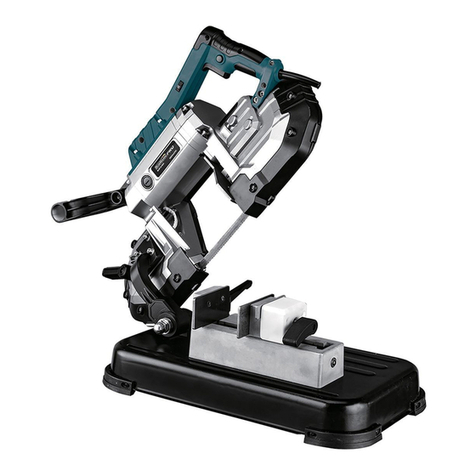
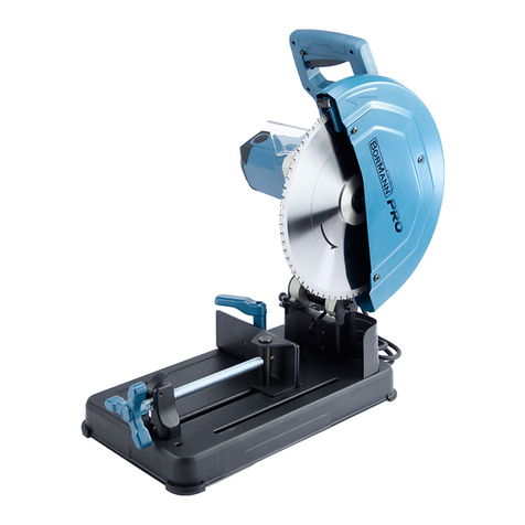
Descripon of Machine Components
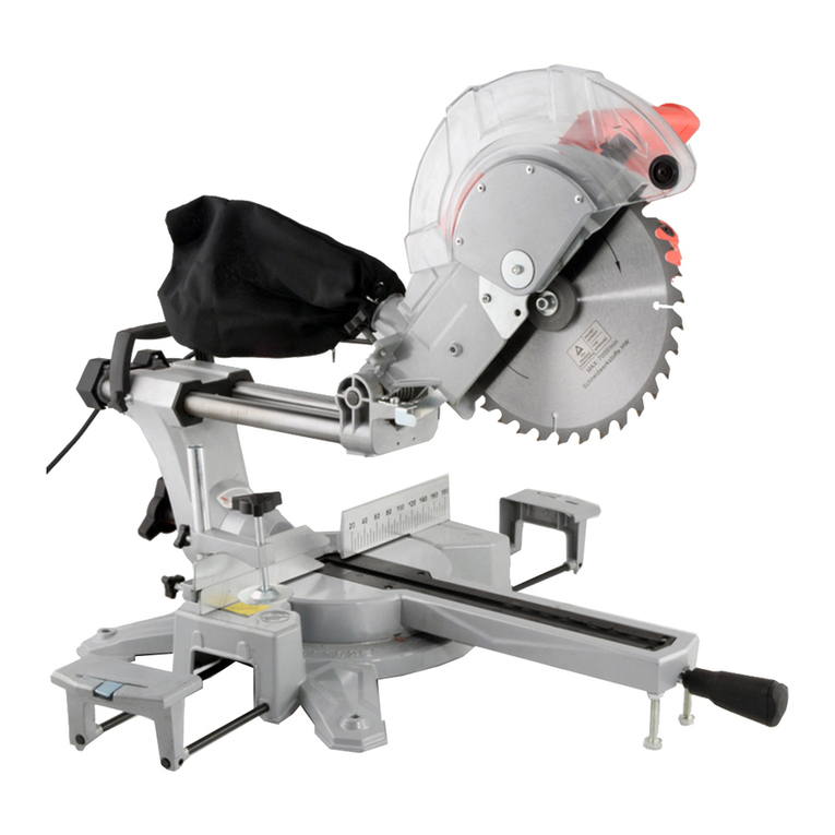
1. D - Handle
2. ON/OFF switch
3. Carry handle
4. Carbon brush cover
5. Interlock
6. Cung depth screw
7. Cung depth nut
8. Angle guide
9. Vice
10. Base plate
Please note that the tool must be placed in a stable posion on a workbench or on bolted to a solid sub-frame. Before starng the machine, check that all covers
and safety equipment are correctly ed. Ensure that the cung disc moves easily. Before you switch on the tool, ensure that all the moving parts move easily and
that the cung disc is installed correctly. Before connecng the tool to the power supply, ensure that the data on the rang plate are idencal to the mains data.
11. Vice crank
12. Quick clamping lever
13. Cung disc
14. Movable guard
Important. Disconnect the machine from the mains supply before starng any seng, assembly and servicing work.
Transport brace / carry-handle ( See Fig. I and Fig. II)
-Push down the saw head by the handle (1) and pull out the interlock (5). (Fig.I)
-Slowly raise the saw head.
Important! The reseng spring lis the saw head automacally. Therefore, do not simply let go of the handle aer cung, but allow the saw head to rise
slowly by applying slight counter-pressure.
-Whenever you want to transport the machine you should use the interlock (5) to anchor the saw head again in its lower posion.(Fig.II)
-The saw is equipped with a carry-handle (3) to make it easier to transport.
Adjusng the stop screw (See. Fig. III)
The downward movement of the cung disc can be adjusted with the cung depth screw (6). This is necessary to compensate wheel wear – as the cung
disc becomes smaller in diameter it would no longer be able to cut right through the workpiece.
- Release the cung depth nut (7).
- Turn the cung depth screw (6) in or out as required.
- Lower the saw head to check whether the cung disc reaches the clamping face of the vise.
- Re ghten the cung depth nut (7).
Set the vice (See Fig. IV)
The mounng for the vice (9) can be enlarged by adjusng the angle guide (8).
- Unscrew the two screws on the angle guide (8).
-Adjust the angle guide (8) to the rear and secure it using the holes provided for it.
- Ensure that the screw connecons are ght again.
Clamp the workpiece in the vice. (See Fig. V)
Your workpiece must be secured very carefully in the vice (6) before you start the cung process.
-Move the quick clamping lever (12) to the le. This lever enables you to adjust the spindle (9) innitely, in other words to turn it, pull it out or push it in.
-Place your workpiece between the two clamping areas (8, 9).
-Move the spindle right up against the workpiece.
-Now move the quick clamping lever (12) to the right.
-Now turn the rotate handle unl the workpiece is securely xed in the vice.
Compleng mitre cuts (See Fig VII, Fig. VIII and Fig. IX)
The vice can be adjusted so that you can complete mitre cuts at angles of 45o - 0o - 45o.
-Undo the two screws on the rear clamping area.
-Adjust the clamping area to the angle you require.
-Tighten the two screws again.
The front clamping area will automacally adjust to the angle you have set.
Change the cung disc (See Fig. X)
-Move the saw head to its highest posion.
-Move the front saw guard upwards. The enre cung disc cover will open.
-Move the ange cover down.
-Push the sha lock to the right.
-Turn the cung disc (13) unl the sha lock engages.
-Unscrew the sha screw by turning it an-clock wise with a suitable socket wrench.
-Remove the sha screw, external ange and the washer.
-Pull the worn cung disc out forwards.
-Before you t the new cung disc, carefully clean the external ange, the washer and the sha screw.
-Fit the new cung disc. Note the direcon of rotaon as you do so.
-Ret the washer and then the external ange.
-Screw in the sha screw again.
Assembly
15. Spindle lock
