F 002 DG9 918 2017-10-16|Bosch Limited
| EPS 610 | 3 en
Contents English
1. Symbols used 4
1.1 In the documentation 4
1.1.1 Warning notices -
Structure and meaning 4
1.1.2 Symbols in this documentation 4
1.2 On the product 4
2. User information 5
2.1 Important notes 5
2.2 Safety instructions 5
3. Product description 6
3.1 Application 6
3.2 Requirements 6
3.3 Delivery specification 6
3.4 Special accessories 6
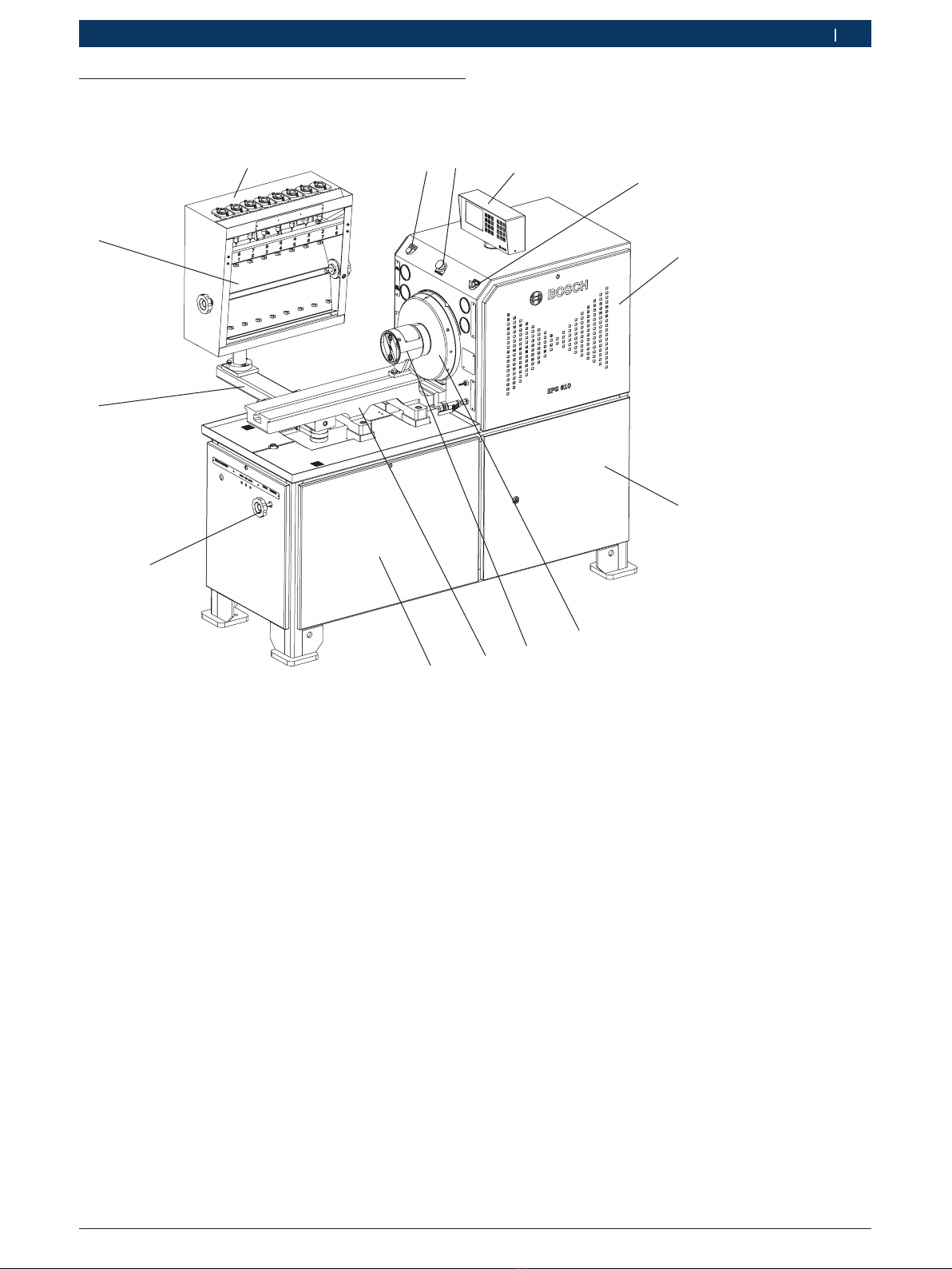
3.5 Description of unit 7
3.5.1 EPS 610 7
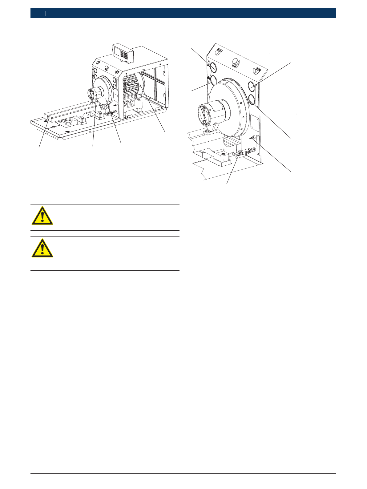
3.5.2 Drive 8
3.5.3 Front panel 8
3.5.4 Frame 8
3.5.5 Measuring glass carrier 8
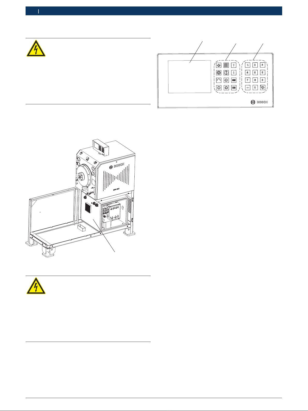
3.5.6 Control cabinet 10
3.5.7 Human Machine Interface (HMI) 10
3.5.8 Test oil supply unit 11
3.5.9 Pressure control valve for high and
low pressure 11
3.6 Test oil tank 11
3.6.1 Cooling the test oil 11
3.6.2 Heating the test oil 12
3.7 Temperature measurement and control 12
3.8 Temperature control for VE pumps 12
3.9 Power supply for start / stop valve
(12/24 V for distributor pumps) 12
4. Initial start-up 13
4.1 Transportation 13
4.2 Unpacking the EPS 610 13
4.3 Moving the EPS 610 to the installation
location 13
4.4 Before turning on for the first time 14
4.4.1 Installation 14
4.4.2 Mains connections 15
4.4.3 HMI connection 15
4.4.4 Test oil connections 16
4.4.5 Connection for cooling water 17
4.4.6 Checking pressure gauges 17
5. Program description 17
5.1 Description of keys on the HMI 17
5.2 Operation of the HMI 18
5.3 Changing the set values 18
5.3.1 Setting the motor speed 18
5.3.2 Change direction of rotation 19
5.3.3 Set number of strokes 19
5.3.4 Oil temperature control 19
5.4 Automatic selection of stroke count
and motor speed 19
5.4.1 Selecting a preset stroke count 19
5.4.2 Selecting a preset motor speed 19
5.5 Saving customer-specific speed rates 20
5.6 Activate stroke counting 20
6. Operation 20
6.1 Switch-on 20
6.2 Switch-off 21
6.3 Emergency stop 21
6.3.1 Activating emergency stop 21
6.3.2 Deactivating emergency stop 21
6.4 Preparing to carry out tests 21
6.5 Checking pre-stroke, start of delivery and
cam offset for in-line pumps 22
6.6 Checking start of delivery for distributor
pumps with pre-stroke specifications 23
7. Troubleshooting 23
7.1 System error messages 24
7.2 Drive error messages 25
8. Maintenance 26
8.1 Cleaning 26
8.2 Spare and wearing parts 26
8.3 Servicing 26
8.3.1 Maintenance intervals 26
8.3.2 Removing contaminated test oil 27
8.3.3 Cleaning the MGT strainer 27
8.3.4 Replacing the filter insert 27
8.3.5 Draining the test oil from the
test oil tank 28
8.3.6 Cleaning the suction strainer 28
8.3.7 Flexible coupling 29
8.3.8 Adjusting the MGT tray 29
9. Decommissioning 30
9.1 Temporary shutdown 30
9.2 Change of location 30
9.3 Disposal and scrapping 30
9.3.1 Substances hazardous to water 30
9.3.2 EPS 610 and accessories 30
10. Technical data 31
10.1 EPS 610 31
10.2 Bench layout 32
10.3 Tightening torques 33
10.3.1 Fastening parts 33
10.3.2 Coupling halves 33
10.4 Machinery noise information
pursuant to the bench safety code 33