manuals.online logo
Brands
  1. Home
  2. •
  3. Brands
  4. •
  5. Bpt
  6. •
  7. Intercom System
  8. •
  9. Bpt HPV/0-2 VR User manual

Bpt HPV/0-2 VR User manual

1
IISTRUZIONI PER
L’INSTALLAZIONE
BPT S.p.A.
30020 Cinto Caomaggiore
Venezia/Italy
07.2001/2405-5000
HPC/1÷4 VR
HPV/0÷2 VR POSTO ESTERNO HPC/1÷4 VR
Togliere la piastrina fermacavi (fig. 6).
Inserire il gruppo audio in alto, vicino
alla testata del telaio (fig. 1-2).
Nel caso di impianti dove può insor-
gere l’effetto Larsen, il microfono può
essere montato in posizione remota,
come indicato nelle figure 3 e 4.
Per scrivere i dati desiderati sul car-
tellino portanome, estrarre il ferma
cartellino e quindi il cartellino (fig. 5).
NOTA. Si possono utilizzare cartellini
portanome personalizzati fino ad un
massimo di 2 mm di spessore.
Effettuare i collegamenti e rimettere la
piastrina fermacavi (fig. 6).
Fissare il telaio alla placca tramite le
due viti in dotazione (fig. 6).
Per montare la placca sulla scatola
incasso avvitare le due viti di fissag-
gio tramite la chiave in dotazione (fig.
7).
Caratteristiche tecniche
• Potenza massima commutabile del
microcontatto: 24V 1A.
• Assorbimento del gruppo di illumi-
nazione: 30mA, 17,5V.
• Temperatura di funzionamento: da
-15 °C a +50 °C.
POSTO ESTERNO HPV/0÷2 VR
Togliere la piastrina fermacavi (fig.
12).
Inserire il gruppo audio-video in alto,
vicino alla testata del telaio (fig. 8-9).
Nel caso di impianti dove può insor-
gere l’effetto Larsen, il microfono può
essere montato in posizione remota,
come indicato nelle figure 10 e 11.
Per scrivere i dati desiderati sul car-
tellino portanome, estrarre il ferma
cartellino e quindi il cartellino (fig. 5).
NOTA. Si possono utilizzare cartellini
portanome personalizzati fino ad un
massimo di 2 mm di spessore.
Effettuare i collegamenti e rimettere la
piastrina fermacavi (fig. 12).
Fissare il telaio alla placca tramite le
due viti in dotazione (fig. 12).
Per montare la placca sulla scatola
incasso avvitare le due viti di fissag-
gio tramite la chiave in dotazione (fig.
13).
Caratteristiche tecniche
• Potenza massima commutabile del
microcontatto: 24V 1A.
• Assorbimento del gruppo di illumi-
nazione: 30mA, 17,5V.
• Temperatura di funzionamento: da
-15 °C a +50 °C.
5218111214
2
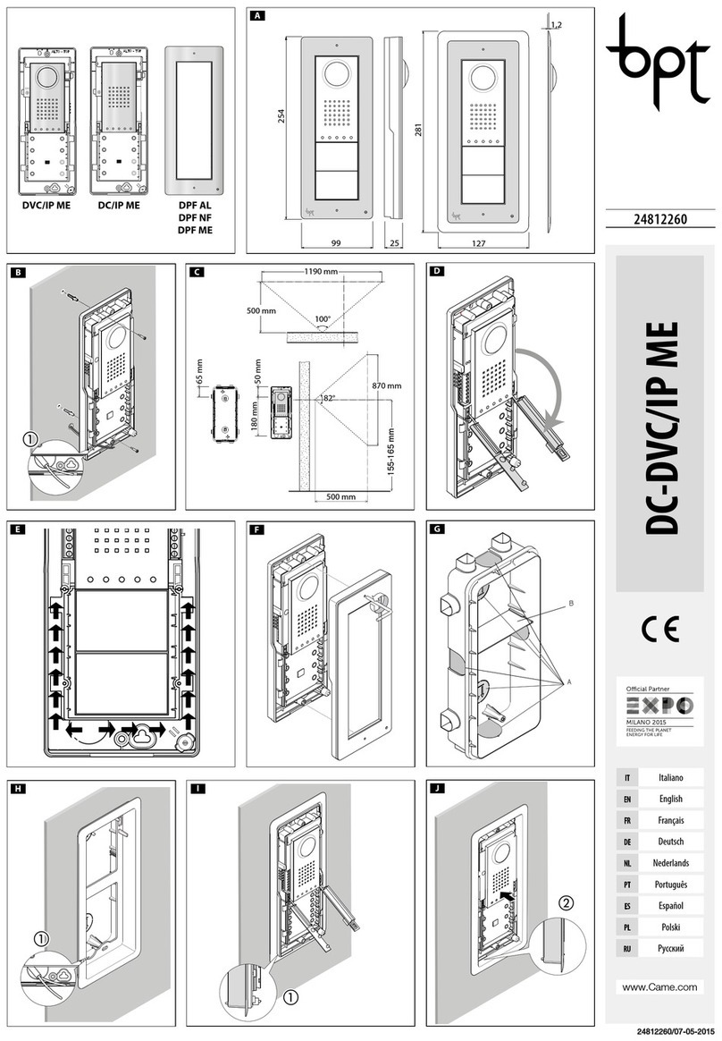
HPC/1÷4 VR ENTRY PANEL
Remove the cable-clamp plate (fig.
6).
Insert the audio module at the top,
near to the top moulding of the chas-
sis (fig. 1-2).
In those installations liable to be
affected by the Larsen effect, the
microphone can be fitted in a remote
position, as indicated in figures 3 and
4.
The name card can be removed and
filled in with the relevant information
by removing the card clip followed by
the actual card itself (fig. 5).
NOTE: Personalized name cards can
be used up to a maximum of 2 mm
thick.
Perform the wiring and refit the cable-
clamp plate (fig. 6).
Secure the chassis to the front plate
using the two screws supplied (fig. 6).
In order to fit the front plate on the
embedding box, screw on the two
fastening screws using the screw-
driver supplied (fig. 7).
Technical features
• Max. switching capacity of the
micro-contact: 24V 1A.
• Current demand of the lighting
module: 30mA, 17.5V.
• Working temperature range: from -15
°C to +50 °C.
HPV/0÷2 VR ENTRY PANEL
Remove the cable-clamp plate (fig.
12).
Insert the audio-video module at the
top, near to the top moulding of the
chassis (fig. 8-9).
In those installations liable to be
affected by the Larsen effect, the
microphone can be fitted in a remote
position, as indicated in figures 10
and 11.
The name card can be removed and
filled in with the relevant information
by removing the card clip followed by
the actual card itself (fig. 5).
NOTE: Personalized name cards can
be used up to a maximum of 2 mm
thick.
Perform the wiring and refit the cable-
clamp plate (fig. 12).
Secure the chassis to the front plate
using the two screws supplied (fig. 12).
In order to fit the front plate on the
embedding box, screw on the two
fastening screws using the screw-
driver supplied (fig. 13).
Technical features
• Max. switching capacity of the
micro-contact: 24V 1A.
• Current demand of the lighting
module: 30mA, 17.5V.
• Working temperature range: from -15
°C to +50 °C.
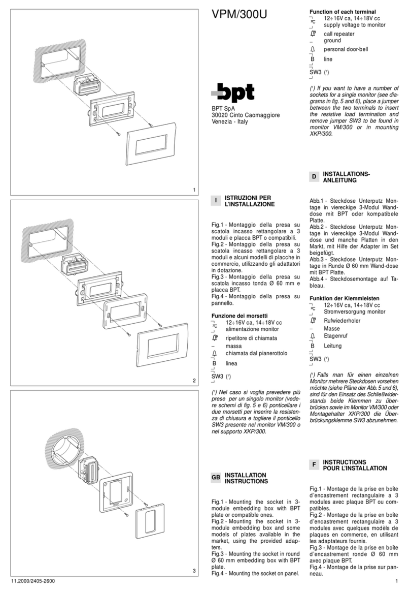
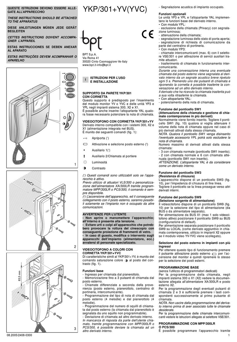
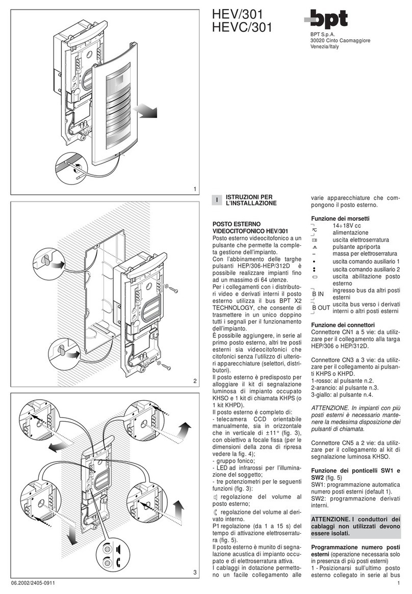
GB INSTALLATION
INSTRUCTIONS
5218111214
1
2
5
DINSTALLATIONS-
ANLEITUNG
AUSSENSTATION HPC/1÷4 VR
Kabelhalterplättchen abnehmen
(Abb. 6).
Audio oben, an der Stirnseite der
Chassis einsetzen (Abb. 1-2).
Bei Anlagen mit möglichem Larsen-
effekt kann das Mikrofon gemäß den
Abbildungen 3 und 4 in Fernstellung
gebracht werden.
Kärtchenhalter und somit Kärtchen
herausnehmen und gewünschte
Daten auf Namenskärtchen schrei-
ben (Abb. 5).
ANMERKUNG. Es können bis zu
max. 2 mm dicke Namenskärtchen
verwendet werden.
Anschlüsse vornehmen und Kabel-
halterplättchen wieder anbringen
(Abb. 6).
Chassis durch die mitgelieferten
Schrauben an das Tableau anschrau-
ben (Abb. 6).
Um das Tableau auf den Up-Kasten
zu montieren, müssen die Arretier-
schrauben mit dem mitgeliefertem
Schlüssel fest zuschraubt werden
(Abb. 7).
Technische Daten
• Max. Schaltkapazität des Mikro-
kontakt: 1A bei 24V.
• Stromaufnahme des Beleuchtung-
einheit: 30mA, 17,5V.
• Betriebstemperatur: von -15 °C bis
+50 °C.
AUSSENSTATION HPV/0÷2 VR
Kabelhalterplättchen abnehmen
(Abb. 12).
Audio-Videosatz oben, an der Stirn-
seite der Chassis einsetzen (Abb. 8-
9).
Bei Anlagen mit möglichem Larsen-
effekt kann das Mikrofon gemäß den
Abbildungen 10 und 11 in Fernstel-
lung gebracht werden.
Kärtchenhalter und somit Kärtchen
herausnehmen und gewünschte
Daten auf Namenskärtchen schrei-
ben (Abb. 5).
ANMERKUNG. Es können bis zu
max. 2 mm dicke Namenskärtchen
verwendet werden.
Anschlüsse vornehmen und Kabel-
halterplättchen wieder anbringen
(Abb. 12).
Chassis durch die mitgelieferten
Schrauben an das Tableau anschrau-
ben (Abb. 12).
Um das Tableau auf den Up-Kasten
zu montieren, müssen die Arretier-
schrauben mit dem mitgeliefertem
Schlüssel fest zuschraubt werden
(Abb. 13).
Technische Daten
• Max. Schaltkapazität des Mikro-
kontakt: 1A bei 24V.
• Stromaufnahme des Beleuchtung-
einheit: 30mA, 17,5V.
• Betriebstemperatur: von -15 °C bis
+50 °C.
FINSTRUCTIONS
POUR L’INSTALLATION
POSTE EXTERIEUR HPC/1÷4 VR
Enlever la plaquette serre-câbles (fig.
6).
Introduire le groupe audio en haut, à
côté de l’embout du châssis (fig. 1-
2).
En cas d’installation où il pourrait se
produire l’effet Larsen, le microphone
pourra être installé à distance
comme indiqué dans les figures 3 et
4.
Pour écrire les données désirées sur
l’étiquette porte-nom, enlever d’a-
bord la protection transparente puis
l’étiquette (fig. 5).
NOTA. Il est possible d’utiliser des
étiquettes porte-nom personnalisées
ayant une épaisseur de 2 mm maxi-
mum.
Effectuer les connexions et remettre
la plaquette serre-câbles (fig. 6).
Fixer le châssis à la platine avec les
deux vis fournies (fig. 6).
Pour visser la platine au boîtier d’en-
castrement, utiliser les deux vis de
fixation et la clé fournie (fig. 7).
Caractéristique techniques
• Pouvoir de coupure du micro-con-
tact: 24V 1A maxi.
• Consommation du groupe d’éclai-
rage: 30mA, 17,5V.
• Température de fonctionnement:
de -15 °C à +50 °C.
POSTE EXTERIEUR HPV/0÷2 VR
Enlever la plaquette serre-câbles (fig.
12).
Introduire le groupe audio-vidéo en
haut, à côté de l’embout du châssis
(fig. 8-9).
En cas d’installation où il pourrait se
produire l’effet Larsen, le microphone
pourra être installé à distance
comme indiqué dans les figures 10 et
11.
Pour écrire les données désirées sur
l’étiquette porte-nom, enlever d’a-
bord la protection transparente puis
l’étiquette (fig. 5).
NOTA. Il est possible d’utiliser des
étiquettes porte-nom personnalisées
ayant une épaisseur de 2 mm maxi-
mum.
Effectuer les connexions et remettre
la plaquette serre-câbles (fig. 12).
FIxer le châssis à la platine avec les
deux vis fournies (fig. 12).
Pour visser la platine au boîtier d’en-
castrement, utiliser les deux vis de
fixation et la clé fournie (fig. 13).
Caractéristique techniques
• Pouvoir de coupure du micro-con-
tact: 24V 1A maxi.
• Consommation du groupe d’éclai-
rage: 30mA, 17,5V.
• Température de fonctionnement:
de -15 °C à +50 °C.
5218111214
4
5218111214
3
3
7
5218111214
6
5218111214
521
8
EINSTRUCCIONES
PARA LA INSTALACION
PLACA EXTERIOR HPC/1÷4 VR
Quitar la plaqueta sujeta-cables (fig.
6).
Introducir el grupo audio en la parte
alta, cerca del cabezal del bastidor
(fig. 1-2).
En el caso de instalaciones en las
cuales se pueda generar el efecto
Larsen, es posible montar el micrófo-
no en posición remota, tal y como
mostrado en las figuras 3 y 4.
Para escribir los datos que se desea
en el letrerito de identificación, retirar
el sujeta-letrero y seguidamente el
propio letrero (fig. 5).
NOTA. Se pueden usar letreritos de
identificación personalizados siem-
pre y cuando no superen los 2 mm
de espesor.
Efectuar las conexiones y colocar de
nuevo en su sitio la plaqueta sujeta-
cables (fig. 6).
Asegurar el bastidor a la plancha con
los dos tornillos incluidos en el sumi-
nistro (fig. 6).
Para montar la plancha a la caja hay
que enroscar los dos tornillos de fija-
ción con la llave que se entrega junto
al equipo (fig. 7).
Caractéristicas técnicas
• Potencia máxima conmutable del
microcontacto: 24V 1A.
• Consumo del grupo de ilumina-
ción: 30mA, 17,5V.
• Temperatura de funcionamiento:
de -15 °C a +50 °C.
PLACA EXTERIOR HPV/0÷2 VR
Quitar la plaqueta sujeta-cables (fig.
12).
Introducir el grupo audio-vídeo en la
parte alta, cerca del cabezal del
bastidor (fig. 8-9).
En el caso de instalaciones en las
cuales se pueda generar el efecto
Larsen, es posible montar el micrófo-
no en posición remota, tal y como
mostrado en las figuras 10 y 11.
Para escribir los datos que se desea
en el letrerito de identificación, retirar
el sujeta-letrero y seguidamente el
propio letrero (fig. 5).
NOTA. Se pueden usar letreritos de
identificación personalizados siem-
pre y cuando no superen los 2 mm
de espesor.
Efectuar las conexiones y colocar de
nuevo en su sitio la plaqueta sujeta-
cables (fig. 12).
Asegurar el bastidor a la plancha con
los dos tornillos incluidos en el sumi-
nistro (fig. 12).
Para montar la plancha a la caja hay
que enroscar los dos tornillos de fija-
ción con la llave que se entrega junto
al equipo (fig. 13).
Caractéristicas técnicas
• Potencia máxima conmutable del
microcontacto: 24V 1A.
• Consumo del grupo de ilumina-
ción: 30mA, 17,5V.
• Temperatura de funcionamiento:
de -15 °C a +50 °C.
PLACA BOTONEIRA HPC/1÷4 VR
Tirar a placa detentora dos cabos
(fig. 6).
Inserir o grupo áudio em cima, próxi-
mo à cabeceira do chassis (fig. 1-2).
No caso de instalações onde se
pode levantar o efeito Larsen, o
microfone pode ser montado na
posição remota, como indicado nas
figuras 3 e 4.
Para escrever os dados desejados
no letreiro porta-nome, extrair o
espelho que fixa o letreiro e em
seguida o letreiro (fig. 5).
NOTA. Podem-se utilizar letreiros
porta-nome personalizados até um
máximo de 2 mm de espessura.
Efectuar as ligações e tornar a colo-
car a placa detentora dos cabos (fig.
6).
Fixar o chassis a la placa através dos
dois parafusos em dotação (fig. 6).
Para montar a placa sobre a caixa de
encaixe apertar os dois parafusos de
fixação através da chave em dotação
(fig. 7).
Caractéristicas técnicas
• Potência máxima comutável do
micro contacto: 24V 1A.
• Consumo do grupo de iluminação:
30mA, 17,5V.
• Temperatura de funcionamento: de
-15 °C a +50 °C.
PLACA BOTONEIRA HPV/0÷2 VR
Tirar a placa detentora dos cabos
(fig. 12).
Inserir o grupo áudio-vídeo em cima,
próximo à cabeceira do chassis (fig.
8-9).
No caso de instalações onde se
pode levantar o efeito Larsen, o
microfone pode ser montado na
posição remota, como indicado nas
figuras 10 e 11.
Para escrever os dados desejados
no letreiro porta-nome, extrair o
espelho que fixa o letreiro e em
seguida o letreiro (fig. 5).
NOTA. Podem-se utilizar letreiros
porta-nome personalizados até um
máximo de 2 mm de espessura.
Efectuar as ligações e tornar a colo-
car a placa detentora dos cabos (fig.
12).
Fixar o chassis a la placa através dos
dois parafusos em dotação (fig. 12).
Para montar a placa sobre a caixa de
encaixe apertar os dois parafusos de
fixação através da chave em dotação
(fig. 13).
Caractéristicas técnicas
• Potência máxima comutável do
micro contacto: 24V 1A.
• Consumo do grupo de iluminação:
30mA, 17,5V.
• Temperatura de funcionamento: de
-15 °C a +50 °C.
PINSTRUÇÕES
PARA A INSTALAÇÃO
4
12
13
5218111214
521
11
5218111214
521
10
521811 12 14
521
9

This manual suits for next models

1

Other Bpt Intercom System manuals

Bpt VM/300 User manual

Bpt

Bpt VM/300 User manual

Bpt KC/2 User manual

Bpt

Bpt KC/2 User manual

Bpt Agata C 200 User manual

Bpt

Bpt Agata C 200 User manual

Bpt VSC/01 User manual

Bpt

Bpt VSC/01 User manual

Bpt EVKIT User manual

Bpt

Bpt EVKIT User manual

Bpt LANDVRA/1-24 User manual

Bpt

Bpt LANDVRA/1-24 User manual

Bpt YVM/300 User manual

Bpt

Bpt YVM/300 User manual

Bpt GSM/i10K User manual

Bpt

Bpt GSM/i10K User manual

Bpt YVL200 UK Operation manual

Bpt

Bpt YVL200 UK Operation manual

Bpt DDVC/08 VR User manual

Bpt

Bpt DDVC/08 VR User manual

Bpt AGATAKIT C 200 UK User manual

Bpt

Bpt AGATAKIT C 200 UK User manual

Bpt Futura X1 User manual

Bpt

Bpt Futura X1 User manual

Bpt VM/100M32 User manual

Bpt

Bpt VM/100M32 User manual

Bpt IMT/200 User manual

Bpt

Bpt IMT/200 User manual

Bpt HEP/306 User manual

Bpt

Bpt HEP/306 User manual

Bpt MTMA/01 Owner's manual

Bpt

Bpt MTMA/01 Owner's manual

Bpt ICP/LR R3 User manual

Bpt

Bpt ICP/LR R3 User manual

Bpt YKP/300 Operation manual

Bpt

Bpt YKP/300 Operation manual

Bpt VSE/200.01 User manual

Bpt

Bpt VSE/200.01 User manual

Bpt DVC/01 User manual

Bpt

Bpt DVC/01 User manual

Bpt MTMAL/01 Owner's manual

Bpt

Bpt MTMAL/01 Owner's manual

Bpt YKP/200+YV(YVC) Operation manual

Bpt

Bpt YKP/200+YV(YVC) Operation manual

Bpt XC/301 Operation manual

Bpt

Bpt XC/301 Operation manual

Bpt YC/300A Operation manual

Bpt

Bpt YC/300A Operation manual

Popular Intercom System manuals by other brands

Aiphone KB-3HRD installation manual

Aiphone

Aiphone KB-3HRD installation manual

Contacta STS-K002L Installation & user guide

Contacta

Contacta STS-K002L Installation & user guide

Viking E-70-BK product manual

Viking

Viking E-70-BK product manual

Smartwares VD38W instruction manual

Smartwares

Smartwares VD38W instruction manual

Fermax iloft manual

Fermax

Fermax iloft manual

Aiphone MK-1GD Installation & operation manual

Aiphone

Aiphone MK-1GD Installation & operation manual

Videx VK4K/6256 Series Installation handbook

Videx

Videx VK4K/6256 Series Installation handbook

Akuvox R20A quick guide

Akuvox

Akuvox R20A quick guide

Vimar ELVOX PIXEL UP 40414.S user manual

Vimar

Vimar ELVOX PIXEL UP 40414.S user manual

Commax DP-RS user manual

Commax

Commax DP-RS user manual

XtendLan DPM-473M user manual

XtendLan

XtendLan DPM-473M user manual

Channel Vision DS3-0212 instructions

Channel Vision

Channel Vision DS3-0212 instructions

Fermax AUDIO 4+n KIT Series manual

Fermax

Fermax AUDIO 4+n KIT Series manual

ANEP BOX TX manual

ANEP

ANEP BOX TX manual

Federal Signal Corporation ez1 echo installation instructions

Federal Signal Corporation

Federal Signal Corporation ez1 echo installation instructions

Gewiss Chorus ANTAS GW19061 user manual

Gewiss

Gewiss Chorus ANTAS GW19061 user manual

ABB Welcome IP H8236 Series product manual

ABB

ABB Welcome IP H8236 Series product manual

SSS Siedle Siedle-Classic CL 111 Series Product information

SSS Siedle

SSS Siedle Siedle-Classic CL 111 Series Product information

manuals.online logo
manuals.online logoBrands
  • About & Mission
  • Contact us
  • Privacy Policy
  • Terms and Conditions

Copyright 2025 Manuals.Online. All Rights Reserved.