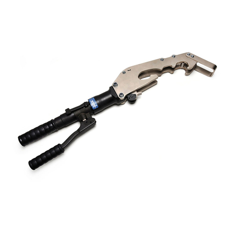
Cembre B500-KV User manual

1
BATTERY OPERATED HYDRAULIC CRIMPING TOOL
OUTIL HYDRAULIQUE DE SERTISSAGE SUR BATTERIE
HYDRAULISCHES AKKU-PRESSWERKZEUG
HERRAMIENTA HIDRÁULICA DE CRIMPADO A BATERÍA
UTENSILE OLEODINAMICO DA COMPRESSIONE A BATTERIA
B500-KV B500A-KV B500E-KV B500T-KV
ENGLISH
FRANÇAIS
DEUTSCH
ESPAÑOL
ITALIANO
OPERATION AND MAINTENANCE MANUAL................................................. 5
NOTICE D’UTILISATION ET ENTRETIEN.........................................................13
BEDIENUNGSANLEITUNG.................................................................................21
MANUAL DE USO Y MANTENIMIENTO .........................................................29
MANUALE D’USO E MANUTENZIONE...........................................................37
19 M 097

2
FIG. / BILD 1 FIG. / BILD 2
FIG. / BILD 3
FIG. / BILD 4
FIG. / BILD 5
4
5
41
49
P
Connector
Connecteur
Kabelschuh
Conector
Connettore
62
42
Die set
Matrices
Presseinsätze
Matrices
Matrici
83
62
7
Battery
Batterie
Akku
Batería
Batteria

3
1 + 3
LED WORKLIGHT / ECLAIRAGE PAR LED / LED-BELEUCHTUNG / LUCES LED / ILLUMINAZIONE LED
2
HEAD / TETE / KOPF / CABEZA / TESTA
4
OPERATING BUTTON / GACHETTE DE COMMANDE / STARTKNOPF / BOTÓN DE ACCIONAMIENTO
/ PULSANTE DI AZIONAMENTO
5
PRESSURE RELEASE BUTTON / GACHETTE DE DECOMPRESSION / DRUCKABLASSKNOPF / BOTÓN
DESBLOQUEO PRESIÓN / PULSANTE SBLOCCO PRESSIONE
6
BATTERY / BATTERIE / AKKU / BATERÍA / BATTERIA
7
BATTERY RELEASE / DEBLOCAGE BATTERIE / AKKU ENTRIEGELUNG / DESBLOQUEO BATERÍA /
SBLOCCO BATTERIA
8
TOUCH BUTTON FOR MENU SELECTION / TOUCHE POUR SELECTIONNER LE MENU / TOUCH-
TASTE FÜR AUSWAHLMENÜ / TECLA PARA SELECCIONAR EL MENÚ / TASTO A SFIORAMENTO PER
SELEZIONE MENU
9
DISPLAY / ECRAN / DISPLAYANZEIGE / PANTALLA / DISPLAY
10
RING FOR SHOULDER STRAP / ANNEAU POUR BANDOULIERE / TRAGERIEMENRING / ANILLO PARA
CORREA / ANELLO AGGANCIO TRACOLLA
FIG. / BILD 6
3
10
4
5
6
7
8
9
2
1

4
– Before using the tool, carefully read the instructions in this manual.
– Avant d'utiliser cet outil, lire attentivement les instructions de cette notice.
– Vor Inbetriebnahme unbedingt die Bedienungsanleitung durchlesen.
– Antes de utilizar la herramienta, leer atentamente las instrucciones en este manual.
– Prima di utilizzare l'utensile, leggere attentamente le istruzioni riportate in questo manuale.
– When operating the tool, keep hands away from the danger zone.
– Au cours du sertissage, tenir les mains éloignées de la zone de travail.
– Während des Verpressens nicht mit den Händen in den Pressbereich gelangen.
– Durante su utilización, mantenga las manos fuera de la zona de peligro.
– Durante l'utilizzo, mantenere le mani fuori dalla zona di pericolo.
– Always close the tool head correctly and securely.
– S'assurer toujours de la parfaite fermeture de la tête.
– Immer darauf achten, dass der Kopf richtig verriegelt ist.
– Asegurarse siempre de que la cabeza está correctamente cerrada.
– Assicurarsi sempre della perfetta chiusura della testa.
WARNING SYMBOLS - SYMBOLES D'AVERTISSEMENT - WARNSYMBOLE -
SÍMBOLOS DE ADVERTENCIA - SIMBOLI DI AVVERTENZA
– Never throw batteries into fire or water.
– Jamais jeter les batteries dans le feu ou dans l'eau.
– Werfen Sie Akkus nicht ins Feuer oder Wasser.
– Nunca tire las baterías al fuego o al agua
– Mai gettare le batterie nel fuoco o in acqua.
– Always recycle the batteries.
– Recycler toujours les batteries.
– Verbrauchte Akkus stets dem Recycling zuführen.
– Reutilizar siempre las baterías.
– Riciclare sempre le batterie.
– Do not discard batteries into domestic refuse or waste disposal.
– Ne pas jeter de batteries dans une poubelle ou autre lieu non prévu à cet effet.
– Verbrauchte Akkus nicht der allgemeinen Abfallentsorgung zuführen.
– No tirar las baterías al cubo de basura o lugar parecido.
– Non buttate le batterie fuori uso nei cestini della spazzatura o luoghi simili.
– User information (Directives 2011/65/EU and 2012/19/EU), see page 46.
– Information pour les utilisateurs (Directives 2011/65/EUet 2012/19/EU) voir page 46.
– Information für den Benutzer (Richtlinien 2011/65/EU und 2012/19/EU) siehe Seite 46.
– Informe para los usuarios (Directivas 2011/65/EU y 2012/19/EU) vease página 46.
– Informazione agli utenti (Direttive 2011/65/EU e 2012/19/EU) vedere pagina 46.
Battery - Batterie - Akku - Batería - Batteria
Tool - Outil - Werkzeug - Herramienta - Utensile
5
(1) Directive 2006/42/EC, annexe 1, point 1.7.4.2 letter u
LpA = weighted continuous acoustic pressure level equivalent.
LpCPeak = maximum value of the weighted acoustic displacement pressure at the work place.
LWA = acoustic power level emitted by the machine.
(2) Directive 2006/42/EC, annexe 1, point 2.2.1.1
Weighted root mean square in frequency of the acceleration the upper limbs are exposed to for each biodynamic
reference axis. Tests carried out in compliance with the indications contained in EN ISO 5349-1/2 Standard, and under
operating conditions much more severe than those normally found.
1. GENERAL CHARACTERISTICS
ENGLISH
B500-KV
B500E-KV B500T-KV B500A-KV
Application range suitable for installing electrical compression connectors on
conductors up to 300 mm
2
(600 MCM)
Rated crimping force
kN (US sh. ton)
63 (7.1)
Minimum crimping force
kN (US sh. ton)
60 (6.75)
Minimum operating pressure
bar (psi) 661 (9587)
Dimensions mm (inches) 305 x 347 x 83 (12 x 13.6 x 3.3)
Weight with battery kg (lbs) 4,3 (9.4)
Motor V DC 18
Operating temperature °C (°F) -15 to +50 (+5 to +122)
Recommended oil TOTAL DIEKAN 1640 or equivalents.
Operating speed
twin speed operation and automatic switching from a rapid
advancing speed of the ram to a slower, more powerful
crimping speed
Safety maximum pressure valve
Rechargeable battery V / Ah / Wh 18 / 5,2 / 93,6
Type CB1852L (Li-Ion)
Weight kg (lbs) 0,66 (1.45)
Battery charger
ASC30-36
Input
type EU
27044000
UK
27045000
AUS/NZ
27047000
USA/CAN
27046000
V / Hz 220 - 240 / 50 - 60 115 / 60
W85
Acoustic noise
(1)
L
pA
dB (A)
73
L
pCPeak
dB (C) 94.5
L
WA
dB (A) 79
Vibration
(2)
m/s
2
0.575 max.

6
ENGLISH
WARNING
Do not use the tool for purposes other than those intended by Cembre.
The operator should concentrate on the work being performed and be careful to maintain
a balanced working position.
The tool is provided with additional external coatings to protect the operator and tool
against accidental brush contact with energised conductors.
Propertrainingtechniquesandpracticesshouldalwaysbeadheredtowhenworkingaround
energised conductors.
Always consult your company’s work rules and methods to select suitable tooling, rubber
insulated gloves, shrouding and other protective equipment.
Under no circumstances should operatives rely solely on the insulating properties of the
tools alone when working around energised conductors.
Priortousepleaseensurethetoolandspecificallytheinsulatingprotectionarenotdamaged.
The tool is unsuitable for continuous use and should be allowed to cool down following
uninterrupted,successivecrimpingoperations;forinstance,havingexhaustedafullycharged
battery in one session, delay battery replacement for a few minutes.
Protect the tool from rain and moisture. Water will damage the tool and battery.
Electro-hydraulic tools should not be operated in pouring rain.
2. INSTRUCTIONS FOR USE
IMPORTANT: In order to avoid damaging the tool, do not operate it at maximum pressure,
without dies inserted in the head.
When introducing or changing dies, the battery must first be removed from the tool.
The part reference includes the following (Ref. to Fig. 7 page 45):
Hydraulic crimping tool.
Li-Ion rechargeable battery (2 pcs).
Battery charger (model depends on the tool version).
Shoulder strap.
Plastic carrying case.
USB cable (Ref. to § 5).
2.1) Preparation
The tool can be easily carried using either the handle or the shoulder strap attached to ring (10)
(Ref. to Fig. 6).
Before starting any work, check the battery charge (Ref. to § 2.8) and recharge if necessary,
following the instructions in the battery charger user manual.

7
ENGLISH
terminal
connector
123
12
1
3
2
3
conductor
conductor
To replace the battery, remove it by pressing the release button (7) (Ref. to Fig. 1), then insert the
new battery, sliding it into the guides until it locks.
Thedisplayshowstheoperationalparametersofthetool;tocustomisethemproceedasdescribed
in § 2.7.
Select the appropriate die set for the connector.
Open the latch (41) and release the upper die holder (42).
Insert one die into the upper die holder (42) until locked by the ball (83) and one die into the
lower die support (49) until locked by the spring clips (62).
Close the head.
Insert the conductor into the connector (Ref. to Fig. 3).
Position the connector between the dies and ensure the correct location of the crimp (Ref. to
Fig. 4).
NOTE: when more compression is
required,proceedaccordingto the
sequence and direction indicated
in the figure.
Ensure that the latch and the upper die holder are fully secured, otherwise damage may
occur during tool operation.
2.2) Die advancement
Press operating button (4) (Ref. to Fig. 4) to activate the motor-pump and advance the lower die.
To halt the advancement, release operating button (4) and the motor will cut out.
Makesurethedies areexactlypositionedonthedesired crimppointotherwisere-opendies
following instructions as per § 2.4 and reposition the connector.
2.3) Compression
By keeping operating button (4) pressed, the motor continues to operate: the ram will gradually
move forward until the two dies touch.
The motor will stop automatically when the set pressure has been reached.
To perform proper compression, press and hold the operating button (4) until the motor
stops automatically.

8
ENGLISH
ERROR
Ï
Ð
Fm= 60.0 kN
Fp= 58.3 kN
Pm= 661 bar
Pp= 485 bar
Fm= 60.0 kN
OK
Pm= 661 bar
OK
3 SEC.
NOTE:Todisplaythemomentaryforceorpressureduring
the work cycle, select the appropriate display from the
menu (Ref. to § 4).When the operating button is released
beforethemotorstopsautomatically,thedisplaywillshow
the peak force (Fp) or the peak pressure (Pp) reached at
that instant.
Tocompletethework,presstheoperatingbuttonagainuntilthemotorstopsautomatically;thedisplay
will show the maximum force or pressure reached followed by "OK" to confirm correct operation.
The display "ERROR", combined with a beep and the LEDs flashing, indi-
cates an incorrect crimping procedure caused by the work cycle being
interrupted before the control parameters (force/pressure) of the tool
are reached.
This error appears when the pressure release button has been operated and the tool has already
reached a pressure >100 bar. In this case, repeat the compression by pressing and holding the
operating button until the motor stops automatically.
2.4) Release of dies
By operating the pressure release button (5) (Ref. to Fig. 4), the ram will retract and open the dies.
2.5) LED Worklights
Whilst the tool is in operation, the compression area is illuminated by two high luminosity LED
Worklights that switch off automatically at the end of the cycle.
The LED Worklights can be disabled by following the procedure described in § 4.2.
2.6) Head rotation
For ease of operation, the tool head can rotate through 180°, allowing the operator to work in the
most comfortable position.
Do not attempt to rotate the head when the hydraulic circuit is pressurised.
2.7) Capacitive touch button for menu selection
This button is located under the display and allows selection of various
screens (Ref. to § 4); it only works when the display is on.
Wearing gloves or using other objects may inhibit the operation of the
button, therefore use a bare finger to apply only a light touch.
Do not apply pressure to or stab at the touch button, a light touch using a bare finger is
sufficient. The command pulse is sent when the finger releases the button.

9
ENGLISH
BATTERY Ï
Ð
max.
BATTERY BATTERY
Ï
Ð
min.
2.8) Battery status
The battery is equipped with LED indicators that indicate the remaining battery life at any time
by pressing the adjacent button (P) (Ref. to Fig. 5):
4 LEDs illuminated: fully charged
2 LEDs illuminated: 50 % capacity
1 LED flashing: minimum charge, replace the battery.
With the battery inserted into the tool, the remaining bat-
tery life can also be checked on the display, via touch but-
ton selection (Ref. to § 4).
The screen shown alongside indicates that the battery Voltage has
droppedbelowaminimum safety threshold;underthese conditionsthe
tool will not start, and it is necessary to recharge or replace the battery.
The approximate time to fully recharge a battery is about 100 minutes.
Aftereachworkingcycle,andaftertheextractionofthebatteryfromthetool,anintegrated
battery cut-off device will operate after 70 s approx.
Then the LED nearest to button (P) will flash 5 times each 14 s approx. The battery will be
reactivated when it is reintroduced into the tool and the operating button is pressed.
2.9) Using the battery charger
Carefully follow the instructions in the battery charger user manual.
3. MAINTENANCE
The tool is robust, completely sealed, and requires very little daily maintenance. Compliance with
the following points, should help to maintain its optimum performance:
3.1) Thorough cleaning
Dust, sand and dirt are a danger for any hydraulic device.
Every day, after use, the tool must be wiped with a clean cloth taking care to remove any residue,
especially close to pivots and moveable parts.
Do not use Hydrocarbons to clean the rubber parts.
3.2) Storage case
When not in use, the tool should be stored and transported in the plastic case, to prevent damage.
The case, type VAL P38, is suitable for storing the tool, the accessories and up to 14 die sets and
pre-prepared compression connectors.
VAL P38: Size 520x432x126 mm (20.5x17.0x5.0 inches). Weight 2,6 kg (5.7 lbs).

10
ENGLISH
4. DISPLAY
The OLED display switches on automatically when the operating or pressure release buttons are
pressed, and off after 60 seconds of non-operation.
The display shows:
The main operational parameters of the tool processed by the circuit board, such as peak pres-
sure or force reached.
Information on the condition of the tool, such as the charge level, the battery temperature and
maintenance requirements.
Any operational or procedural ERRORS.
Use the touch button (8) to navigate through the menu screens to manage INFORMATION AND
SELECTION:
4.1) INFORMATIONSCREENS:displaya pre-determinedparameterwhich willthenappeareach
time the tool is started and during the entire work cycle.
B500
13AJ002
Fm= 60.0 kN
Fp = 24.5 kN
Fm= 6.75 ton
Fp = 2.75 ton
Pm= 661 bar
Pp = 312 bar
10
-34990
3
BATTERY
Pm= 9587 psi
Pp = 4525 psi
Fm: Minimum set force, expressed in kN.
Fp: Peak force reached, expressed in kN,
(screen as factory setting).
Fm: Minimum set force, expressed in US sh. tons.
Fp: Peak force reached, expressed in US sh. tons.
Pm: Minimum set pressure, expressed in bar.
Pp: Peak pressure reached, expressed in bar.
Pm: Minimum set pressure, expressed in psi.
Pp: Peak pressure reached, expressed in in psi.
Battery charge level.
No. of cycles performed.
No. of cycles before scheduled recommended maintenance.
Cembre logo, tool model.
tool serial no.

11
ENGLISH
LED
OFF
LED
ON
LED
OFF LED
ON
35001
3
BATTERY Ï
Ð
Ï
Ð
BATTERY
Ï
Ð
RESET
SW:S1J41AH
3 SEC.
To make a selected screen operational and appear at each start-up of the
tool, operate the touch button for at least 3 seconds; a continuous beep
will confirm the setting.
Thecapacitive menu selection button maynotwork iftouchedusingobjectsorwhenwear-
ing gloves, therefore always operate it using a bare finger.
4.2) SELECTION SCREENS: control parameters that cannot be set as automatic upon start-up
of the tool can be changed by operating the touch button:
Enabling/disabling the LED Worklights (factory setting LED ON)
When the screen is displayed,
touch the button for at least 3
seconds to deactivate or re-
activate operation of the LED
Worklights during tool use; a
continuous beep will confirm
the setting.
Return to original factory settings / firmware version
When the "RESET" screen is displayed, return the tool to its factory setting by operating the touch
button for at least 3 seconds; a beep will confirm the setting.
The RESET screen also shows the firmware version of the circuit board.
4.3) WARNINGS: these appear during operation and notify the operator of the status of the tool:
LOW BATTERY: replace the battery.
NOTE: whenthe batteryVagefallsbelowa minimumsafetythreshold, thetool
will not start; although it is still possible to end the work cycle in progress.
BATTERYTEMPERATUREHIGH:removethebatteryandwaituntilitcoolsdown.
NO. OF CYCLES TO MAINTENANCE REACHED:
the tool continues to work however, it is recommended that it is sent to
Cembre for a complete overhaul (see § 6).
NOTE: this message, together with a beep, will reappear when the tool has
been idle for 30 seconds.

12
ENGLISH
4.4) ERRORS: these appear during operation, combined with a beep and flashing LED Worklights,
to notify the operator of procedural or operational errors.
Message Error description Solution
ERROR
Ï
Ð
The pressure release button (5) was
pressed before the control parameters
were reached (Force/Pressure).
Repeat the work cycle and wait for the
motor to stop automatically.
Interruption of the signal from the NTC
temperature probe of the battery.
Replace the battery.
If the problem persists, please contact
Cembre.
001
Ï
Ð
Abnormal power consumption of the mo-
tor for more than 3 seconds.
The tool stops.
Wait for the display to turn off (60 sec.)
or remove and re-insert the battery, then
re-start the tool.
If the error occurs frequently, contact
Cembre.
002
Ï
Ð
Outputvoltageofthepressuretransmitter
is out of the pre-set range.
Repeat the work cycle; if the error occurs
frequently, contact Cembre.
003
Ï
Ð
Failure to reach the set pressure within
30 seconds of continuous operation of
the machine.
Repeat the work cycle; if the error occurs
frequently, contact Cembre.
004
Ï
Ð
Overcharging of the battery with protec-
tion tripping.
The tool stops.
Wait for the display to turn off (60 sec.)
or remove and re-insert the battery, then
re-start the tool.
If the error occurs frequently, contact
Cembre.
Error screens are displayed for about 30 secondsbefore being reset, but will display repeat-
edly in the event of permanent anomalies.
5. CONNECTION TO COMPUTER (Smartool technology)
The memory card integrated in the tool records operating datafor
transfer via the USB cable supplied.
To view and manage this data, go to www.cembre.com and
register in the dedicated area, then download the free Cembre
software CEM_SWBT01.
Keeping the Firmware of the tool updated, via free of charge
download from here, will optimise the tool’s performance.
NTC
FAULT

13
1. CARACTERISTIQUES GENERALES
B500-KV
B500E-KV B500T-KV B500A-KV
Domaine d'application: conçu pour le sertissage des connecteurs électriques
jusqu' à 300 mm
2
(600 MCM)
Force nom. de sertissage
kN (US sh. ton)
63 (7.1)
Force min. de sertissage
développée
kN (US sh. ton)
60 (6.75)
Pression min. de travail bar (psi) 661 (9587)
Dimensions mm (inches) 305 x 347 x 83 (12 x 13.6 x 3.3)
Poids avec batterie kg (lbs) 4,3 (9.4)
Moteur V DC 18
Température de fonction-
nement: °C (°F) -15 à +50 (+5 à +122)
Huile recommandée: TOTAL DIEKAN 1640 ou équivalents
Avance rapide:
l’outil passe automatiquement de la vitesse rapide d’appro-
che des matrices à la vitesse lente de sertissage
Sécurité valve de surpression
Batterie rechargeable V / Ah / Wh 18 / 5,2 / 93,6
Type CB1852L (LI-Ion)
Poids kg (lbs) 0.66
Chargeur de batterie
ASC30-36
Alimentation
type EU
27044000
UK
27045000
AUS/NZ
27047000
USA/CAN
27046000
V / Hz 220 - 240 / 50 - 60 115 / 60
W85
Bruit aérien sonore
(1)
L
pA
dB (A) 73
L
pCPeak
dB (C) 94.5
L
WA
dB (A) 79
Vibrations
(2)
m/s
2
0.575 maxi.
FRANÇAIS
(1) Directive 2006/42/CE, annexe 1, point 1.7.4.2, lettre u
LpA = niveau de pression sonore continue équivalente pondérée A sur le poste de travail.
LpCPeak = valeur de pression sonore instantanée pondérée C sur le poste de travail.
LWA = niveau de puissance acoustique dégagée par la machine.
(2) Directive 2006/42/CE, annexe 1, point 2.2.1.1
Valeur quadratique moyenne pondérée en fréquence de l'accélération à laquelle sont exposés les membres supérieurs
pour chaque axe biodynamique de référence. Relevés réalisés suivant les indications de la Norme EN ISO 5349-1/2,
dans des conditions de service largement représentatives des conditions d'emploi normales.

14
FRANÇAIS
AVERTISSEMENT
Ne pas utiliser cet outil à des fins différentes que celles prévues par le constructeur.
Restez bien attentif tout au long du travail, ne soyez pas distrait, ne perdez pas l’équilibre
pendant l'utilisation.
L’outil est équipé d’un revêtement supplémentaire afin de protéger l’utilisateur contre tout
contact accidentel avec un câble sous tension.
Les techniques appropriées et les règlesde sécurité doivent toujours être strictement appli-
quées lors d’une opération sous tension.
Consultersystématiquementlesprocéduresdetravaildevotresociétéafindechoisirl’outil-
lage approprié, gants isolés ou tout autre matériel de protection.
Les utilisateurs ne doivent en aucun cas compter uniquement sur les propriétés isolantes
de l’outil lorsqu’ils travaillent près des conducteurs sous tension.
Avant chaque utilisation assurez-vous que l’isolant de l’outil n’est pas endommagé.
L’outil n’est pas conçu pour une utilisation en continu; après avoir effectué une quantité de
sertissages consécutifs à partir d’une batterie complètement chargée, au moment du rem-
placement de la batterie, nous suggérons d’observer une période d’arrêt pour permettre
le refroidissement de l’outil.
Protéger l’outil de la pluie et de l’humidité. L’eau pourrait endommager l’outil et la batterie,
les outils hydro-électriques ne devraient pas être utilisés sous la pluie.
2. INSTRUCTIONS D'UTILISATION
IMPORTANT: Pour éviter d’endommager l’outil, il est déconseillé de l’actionner à vide et à
la pression maximale, sans avoir inséré les matrices dans la tête.
Les opérations d’introduction ou de remplacement des matrices doivent être effectuées
avec l’outil dépourvu de batterie.
L' ensemble comprend (Voir Fig. 7 page 45):
Outil hydraulique de sertissage.
Batterie rechargeable Li-Ion (2 pcs).
Chargeur de batterie (différent en fonction de la version de l'outil).
Bandoulière.
Coffret de rangement.
Câble USB ( Voir § 5).
2.1) Mise en service
L’outil peut être transporté facilement grâce à sa poignée et à la bandoulière accrochée par l'anneau
(10) (Voir Fig. 6).
Avant de commencer toute opération, contrôler l’état de charge de la batterie (voir § 2.8)
et, si nécessaire, la recharger en suivant les instructions contenues dans le manuel d’utili-
sation du chargeur de batteries.

15
FRANÇAIS
Pour remplacer la batterie, la retirer en appuyant sur le mécanisme de déblocage (7) (voir Fig. 1),
puis introduire la nouvelle batterie en la faisant coulisser sur les guides jusqu’au blocage complet.
L’écran permet d’afficher les paramètres opérationnels de l’outil. Pour personnaliser ces derniers,
suivre les instructions décrites au § 2.7.
Choisir le couple de matrices approprié pour le type de connexion à réaliser; pour cela, consulter
le catalogue.
Ouvrir la tête de l'outil en écartant le levier (41), libérant ainsi le porte matrice supérieur (42) qui
s'écartera complètement (Voir Fig. 2).
Insérer les matrices dans leur logement respectif (Voir Fig. 2) dans le porte matrice supérieur (42)
jusqu'à ce qu'il soit verrouillé par la bille (83) et dans le support de matrice inférieure (49) jusqu'à
ce qu'il soit verrouillé par les ressorts (62).
Refermer la tête.
Insérer le conducteur dans le connecteur (Voir Fig. 3).
Positionner ce dernier entre les deux matrices en alignant la zone à sertir avec l'empreinte des
matrices (Voir Fig. 4).
REMARQUE:s’ilestnécessairede
procéderàplusieurssertissagesde
cosses ou de manchons, suivre la
séquence et la direction reportée
sur l’illustration en espaçant les
empreintes de façon uniforme.
Avant de poursuivre les opérations, vérifier que la tête soit parfaitement fermée.
2.2) Avance des matrices
Appuyer sur la gâchette de commande (4) (Voir Fig. 4) pour mettre en marche le groupe moteur
pompe; les matrices commencent alors à se rapprocher du connecteur.
Lagâchettedecommande(4)relâchée,lemoteuretl'avancedesmatricescessentimmédiatement.
S'assurerquelesmatricessontbienpositionéessurlazoneàsertir,sinondessererlesmatrices
en suivant les instructions du § 2.4 et repositioner le connecteur.
2.3) Sertissage
En maintenant pressée la gâchette de commande (4), on maintient la rotation du moteur; le
piston avance progressivement jusqu'à ce que les matrices arrivent en butée l'une contre l'autre.
L’outil s’arrêtera automatiquement dès qu’il aura atteint la pression de tarage.
Pour effectuer un bon sertissage, maintenir la gâchette de commande (4) pressée jusqu’à
l’arrêt automatique du moteur.
cosse
manchon
123
12
1
3
2
3
conducteur
conducteur

16
FRANÇAIS
ERROR
Ï
Ð
Fm= 60.0 kN
Fp= 58.3 kN
Pm= 661 bar
Pp= 485 bar
Fm= 60.0 kN
OK
Pm= 661 bar
OK
3 SEC.
REMARQUE: Pour afficher la force ou la pression en
temps réel, lors du cycle de travail, configurer les écrans
correspondants (voir § 4). En relâchant le bouton de
démarrage avant l’arrêt automatique du moteur, l’écran
afficherales valeursdepicdelaforce (Fp)etdelapression
(Pp) atteintes à ce moment.
Pour terminer l’opération, ré-appuyer sur la gâchette de commande jusqu’à l’arrêt automatique
du moteur; l’écran affichera la force ou la pression maximale atteinte, suivie de l’inscription "OK"
indiquant que l’opération a été correctement effectuée.
Lemessage"ERROR"associéàl’avertisseursonore ainsique leclignote-
ment des LED indiquent que la procédure de sertissage n’a pas été cor-
rectement effectuée en raison d’un arrêt anticipé du cycle de travail
avant d’avoir atteint les paramètres réglés (force/pression) de l’outil. Ce message d’erreur s’affiche
lorsque l’opérateur appuie sur la gâchette de déblocage pression après que l’outil ait atteint une
pression > 100 bar. Dans ce cas, effectuer à nouveau le sertissage en maintenant la gâchette de
commande appuyée jusqu’à l’arrêt automatique du moteur. Pour terminer l’opération, ré-appuyer
sur la gâchette de commande jusqu’à l’arrêt automatique du moteur; l’écran affichera la force ou la
pression maximale atteinte, suivie de "OK" indiquant que l’opération a été correctement effectuée.
2.4) Réouverture des matrices
En appuyant à fond sur la gâchette de déblocage pression (5) (Voir Fig. 4), on provoque le retour
du piston et par conséquent l'ouverture des matrices.
2.5) Led
Lors de l’actionnement de l’outil, la zone de sertissage est éclairée au moyen de deux LED haute
luminosité qui s’éteignent automatiquement à la fin du cycle.
Pour désactiver les LED, suivre la procédure décrite au § 4.2.
2.6) Rotation de la tête
La tête de l'outil pivote de 180° par rapport au corps, permettant à l'utilisateur de travailler dans la
meilleure position.
Ne pas forcer la rotation de la tête, lorsque le circuit hydraulique est sous pression.
2.7) Touche tactile de type capacitif
Cettetoucheestsituéesousl’écranetpermetdesélectionnerlesdifférents
écrans (voir § 4); elle fonctionne uniquement lorsque l’écran est allumé
et il suffit de l’effleurer à mains nues. L’utilisation de gants ou d’autres
objets risquerait de compromettre son activation.
Ne jamais appuyer avec force sur la touche tactile, il suffit de l’effleurer avec un doigt, à
mains nues. La commande envoie l’impulsion dès le retrait du doigt.

17
FRANÇAIS
BATTERY Ï
Ð
max.
BATTERY BATTERY
Ï
Ð
min.
2.8) Autonomie de la batterie
La batterie est équipée d’indicateurs à LED qui permettent de contrôler, à tout moment, son
autonomie résiduelle en appuyant sur la touche (P) (voir Fig. 5):
4 led allumées: autonomie maximale
2 led allumées: autonomie à 50 %
1 led clignotante: autonomie minimale, remplacer la batterie.
Lorsque la batterie est insérée dans l’outil, il est possible de
vérifierl’autonomierésiduelleàpartirdel’écran,enappuyant
sur la touche tactile (voir § 4).
L’écran ci-contre indique que la batterie est déchargée et que sa tension
estdescendueau-dessousduseuilminimaldesécurité;danscettesitua-
tion, l’outil ne démarre pas, il est donc nécessaire de recharger ou de
remplacer la batterie.
À titre indicatif, le délai de recharge complète de la batterie correspond à environ 100 min.
A la fin de chaque cycle de travail comme à l’extraction de la batterie de l’outil, un dispositif
électronique arrête automatiquement la batterie après environ 70 s.
Pour confirmer cette opération, la led la plus proche du bouton (P) clignotera 5 fois en 14 s
(approximativement). La batterie est réactivée dès sa réintroduction dans l’outil, ou en appuyant
sur le bouton d’actionnement.
2.9) Utilisation du chargeur de batterie
Suivre attentivement les instructions indiquées sur le manuel.
3. ENTRETIEN
L'outilestrobuste,complètementscelléetnenécessiteaucunepréoccupationouattentionparticulier.
Lesrecommandationsquisuiventsontnéanmoinssouhaitablespourassurerunelongévitéoptimum:
3.1) Nettoyage élémentaire
Veiller à protéger l'outil de la poussière, du sable et de la boue qui sont un danger à tout système
hydraulique. Chaque jour après utilisation, l'outil doit être nettoyé à l'aide d'un chiffon propre, tout
particulièrement aux endroits de pièces mobiles.
Ne jamais utiliser d’hydrocarbures pour le nettoyage des parties en caoutchouc.
3.2) Rangement
Au repos, pour protéger l'outil des coups accidentels et de la poussière, il convient de le ranger
dans le coffret. Ce coffret (type VAL P38), adapté pour contenir l'outil, ses accessoires et 14 paires de
matricesacommedimensions:520x432x126mm(20.5x17.0x5.0inches)etunpoidsde2,6kg(5.7lbs).

18
FRANÇAIS
4. ECRAN
L’écran OLED s’active lors du démarrage de l’outil et se désactive automatiquement au bout de 60
secondes d’inutilisation de l’outil.
L’écran permet d’afficher:
Les principaux paramètres opérationnels de fonctionnement de l’outil, configurés par la carte
électronique, tels que la pression ou la force développée.
Informations sur l’état de l’outil telles que le niveau de charge, la température de la batterie et
besoin éventuel d’entretien.
ERREURS éventuelles de fonctionnement ou de procédure.
Il est possible de se déplacer dans le menu à l’aide de la touche tactile (8) et de gérer les ÉCRANS
D’INFORMATION ET DE SÉLECTION:
4.1) ECRANS D’INFORMATION affichent à l’écran un paramètre donné qui s’affichera ensuite à
chaque démarrage de l’outil et tout au long du cycle de travail.
B500
13AJ002
Fm= 60.0 kN
Fp = 24.5 kN
Fm= 6.75 ton
Fp = 2.75 ton
Pm= 661 bar
Pp = 312 bar
10
-34990
3
BATTERY
Pm= 9587 psi
Pp = 4525 psi
Fm: Force minimale de réglage, exprimée en kN.
Fp: Force atteinte en temps réel, exprimée en kN
(écran tel que configuré par les paramètres standards d’usine).
Fm: Force minimale développée, exprimée en tonnes courtes (USA).
Fp: Force atteinte en temps réel, exprimée en tonnes courtes (USA).
Pm: Pression minimale de réglage, exprimée en bar.
Pp: Pression atteinte en temps réel, exprimée en bar.
Pm: Pression minimale de réglage, exprimée en psi.
Pp: Pression atteinte en temps réel, exprimée en psi.
Niveau de charge de la batterie.
Nbr de cycles effectués.
Nbr de cycles restant à effectuer lors de l’entretien ordinaire.
logo Cembre, série outil.
n° de série de l’outil.

19
FRANÇAIS
35001
3
BATTERY Ï
Ð
Ï
Ð
BATTERY
Ï
Ð
RESET
SW:S1J41AH
3 SEC.
Unefoisquel’écranprésélectionnés’estaffiché,pourlerendreopérationnel
et fixe à chaque démarrage de l’outil, maintenir la touche tactile appuyée
pendant une période prolongée (au moins 3 secondes). Un signal sonore
continu confirmera la configuration effective.
La touche capacitive risque de ne pas fonctionner si celle-ci est effleurée avec des objets
ou des gants, appuyer sur cette touche uniquement à mains nues.
4.2) ECRANS DE SELECTION: permettent de modifier certains paramètres de réglage, ils ne
peuvent être configurés de manière automatique au démarrage de l’outil; pour les activer, il est
toujours nécessaire d’appuyer sur la touche tactile.
Activation/désactivation des LED (paramètre standard d’usine: LED ACTIVÉE)
Une fois l’écran affiché et lors
de l’utilisation de l’outil, pour
le désactiver ou réactiver le
démarrage des LED, maintenir
la touche tactile appuyée pen-
dantunepériodeprolongée(au
moins 3 secondes). Un signal
sonore continu confirmera la
configuration effective.
Retour au paramètres d’usine de départ / Version du firmware
Unefois l’écran"RESET"affiché,maintenir latouchetactileappuyéependant unepériodeprolongée
(au moins 3 secondes). Un signal sonore continu confirmera la configuration effective.
L’écran RESET affiche également la version du firmware de la carte électronique.
4.3) AVERTISSEMENT s’affichent lors du fonctionnement et fournissent des informations à
l’opérateur sur l’état de l’outil:
BATTERIE DÉCHARGÉE: procéder à son remplacement.
REMARQUE : lorsque la tension de la batterie est inférieure au seuil mini-
mal de sécurité, l’outil ne démarre pas mais l’opérateur peut, quoiqu’il
en soit, terminer le cycle de travail en cours.
TEMPÉRATURE ÉLEVÉE DE LA BATTERIE: retirer la batterie et patienter
jusqu’à ce qu’elle se refroidisse.
UNE FOIS LE NBR DE CYCLES PREVU POUR L’ENTRETIEN ORDINAIRE
EFFECTUE: l'outil continue à fonctionner, il est recommandé d’envoyer
l’outil à Cembre afin de procéder à une révision complète (voir § 6).
REMARQUE: ce message, associé à un signal sonore, apparaît à nouveau
au bout de 30 secondes d’inutilisation de l’outil.
LED
OFF
LED
ON
LED
OFF LED
ON

20
FRANÇAIS
4.4) ERREURS: apparaissent lors du fonctionnement. Lorsqu’elles sont associées à un signal
sonore et lumineux, ils indiquent à l’opérateur la présence d’éventuelles erreurs de procédure ou
de fonctionnement.
Message Description erreur Solution
ERROR
Ï
Ð
Actionnementdelagâchettededéblocage
pression(5)avantquel’outiln’aitatteintles
paramètres de réglage (Force/Pression).
Procéder à nouveau au cycle de travail et
attendre l’arrêt automatique du moteur.
Interruption du signal de la sonde de
température NTC de la batterie.
Remplacer la batterie.
Si le problème persiste, contacter Cembre.
001
Ï
Ð
Absorptionanormaledecourantdelapart
du moteur pendant plus de 3 secondes.
L'outil s’arrête.
Patienter jusqu’à l’arrêt de l’écran (60
secondes) ou retirer, puis réinsérer la bat-
terie. Redémarrer l’outil.
Si ce signal d’erreur apparaît souvent,
contacter Cembre.
002
Ï
Ð
Tensiondesortiedel’émetteurdepression
en dehors de l’intervalle configuré.
Procéderànouveauaucycledetravail.Sice
signald’erreurapparaîtsouvent,contacter
Cembre.
003
Ï
Ð
Impossible d’atteindre la pression de
tarage dans les 30 secondes à compter de
l’actionnement continu de l’outil.
Procéderànouveauaucycledetravail.Sice
signald’erreurapparaîtsouvent,contacter
Cembre.
004
Ï
Ð
Surchargedelabatterieavecactionnement
de la protection.
L'outil s’arrête.
Patienter jusqu’à l’arrêt de l’écran (60
secondes) ou retirer, puis réinsérer la bat-
terie. Redémarrer l’outil.
Si ce signal d’erreur apparaît souvent,
contacter Cembre.
Leserreursrestentaffichéesàl’écranpendantenviron30secondes,puisl’erreurestréinitiali-
sée. Elles se présentent à nouveau en cas d’anomalie permanente.
5. CONNEXION A L’ORDINATEUR (Smartool technology)
Le fichier de mémoire intégrée dans l’outil permet d’enregistrer
les paramètres de fonctionnement et de pouvoir les transférer
vers un ordinateur par l’intermédiaire du câble USB fourni. Pour
visualiser et gérer les données mémorisées, le logiciel Cembre
CEM_SWBT01 est disponible gratuitement après enregistrement
dans le domaine réservé du site www.cembre.com. Dans ce
domaine réservé, il sera alors possible de trouver les mises à jour
éventuelles des firmwares permettant à vos propres outils une
meilleure efficacité et d’améliorer leurs performances.
NTC
FAULT
This manual suits for next models
3
Table of contents
Languages:
Other Cembre Tools manuals

Cembre
Cembre TC050Y User manual

Cembre
Cembre HTEPE.DET12 User manual

Cembre
Cembre HP1 User manual

Cembre
Cembre RHM50 User manual

Cembre
Cembre RHTD1724 User manual

Cembre
Cembre HT-TC0851 User manual

Cembre
Cembre HTEPE.DET10 User manual

Cembre
Cembre CMB3 Parts list manual

Cembre
Cembre MT-FC48N User manual

Cembre
Cembre B-FL750ND User manual

Cembre
Cembre TC085 User manual

Cembre
Cembre HT-TRC Operating instructions

Cembre
Cembre ht51 User manual

Cembre
Cembre TC04 User manual

Cembre
Cembre PNB-1 User manual

Cembre
Cembre RH-FL75 User manual

Cembre
Cembre RHM132 User manual

Cembre
Cembre B68RC3-85 User manual

Cembre
Cembre CP1086-W-1000-KV User manual

Cembre
Cembre HP4-R User manual