manuals.online logo
Brands
  1. Home
  2. •
  3. Brands
  4. •
  5. Cembre
  6. •
  7. Tools
  8. •
  9. Cembre HTEPE.DET12 User manual

Cembre HTEPE.DET12 User manual

1
HYDRAULIC TOOL
HTEPE.DET12 HTEPE.DET16
ENGLISH OPERATION AND MAINTENANCE MANUAL
19 M 069 E
2
WARNINGS
– Before using the tool, carefully read the instructions in this manual.
– When operating the tool, keep hands away from the danger zone.
– Always wear safety gloves when operating.
2
1
123
3
TG0350
3
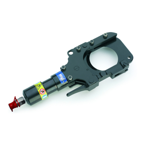
HTEPE.DET12 system consists of:
– Pump unit
– Hydraulic head type RHTEPE-S
– Plunger type OG 13.2T (qty 2)
– GO / NO GO gauge type CAL 22.23
– Plastic case VAL-P14
–Application range:
HTEPE.DET12:
suitable for installing rail web electrical connection system having
M12 bolt (e.g. AR61, AR65, AR261, AR265).
HTEPE.DET16:
suitable for installing rail web electrical connection system having
M16 bolt (e.g. AR6116, AR6516, AR26116, AR26516).
–Installation force: ........................................................................................................................55 kN
–Rated operating pressure:.......................................................................................................700 bar (10000 psi)
–Flexible hose: length..................................................................................................................900mm
–Dimensions (pump body): length ........................................................................................285mm
width..........................................................................................130 mm
–Dimensions (head): length RHTEPE-S....................................................................116 mm
length RHTEPE-S16...............................................................133 mm
width..........................................................................................67,5mm
diameter ...................................................................................48 mm
–Weight: ............................................................................................................................................3,8 kg
–Recommended oil:......................................................TOTAL DIEKAN 1640
or equivalent
–Safety: the tool is provided with a maximum pressure valve.
2.1) Setting
Connect the male coupler of the head to the female coupler on the tool hose; ensure that the couplers
are securely fitted.
Before connecting or disconnecting the head and the hose, ensure that the ram of the head is
fully retracted.
1. GENERAL CHARACTERISTICS
2. INSTRUCTIONS FOR USE
HTEPE.DET16 system consists of:
– Pump unit
– Hydraulic head type RHTEPE-S16
– Plunger type OG 16.2T (qty 2)
– GO / NO GO gauge type CAL 22.23
– Plastic case VAL-P14
4
2.2)
Installation procedure for AR61, AR65, AR6116, AR6516 rail web electrical connections
–Drill rail web or, if already drilled, use a suitable reamer to clean the hole (Fig. 1).
–Check the size of the hole with the CAL 22.23 “GO/NO GO” gauge (Fig. 2a):
- The hole size is correct if only the green part enters the hole.
-If the red part enters, the hole is too large, in this case
it is necessary to drill a new hole.
Using the same gauge, check the rail thickness (Fig. 2b):
- If the yellow band protrudes, use the AR65... series.
- If the yellow band does not protrude, use the AR61.... series.
–Insert the AR...-1 copper bush into the rail web hole (Fig. 3).
–
Ensure that the ram in the head is fully retracted and then firmly screw and tighten
the stem of the
plunger onto the tool head (Fig. 4).
–
I
ntroduce the stem of the plunger into the AR...-1 copper bush from the unflanged side
and s
crew and
tighten the insert of the plunger OG... onto the stem
(Fig. 5) u
sing the recess in the gauge CAL22.23.
Plungers OG13.2T and OG16.2T are composed
of 2
separate items: insert and stem.
To rapidly execute subsequent extrusion opera
tions, it
is sufficient to unscrew the insert, leaving
the stem firmly
screwed onto the head.
–
Operate the moveable handle of the tool (Fig. 6) to pull the plunger
OG..
. completely through the
bush and extrude the bush onto the surface of the hole.
At the end of the operation, press the pressure release lever (20) to retract the ram (01).
–The bush will also extrude itself around the opposite side of the rail web (Fig. 7).
2.3) Conductor assembly
– Crimp the lug onto the conductor.
– Assemble all pieces as shown in Fig. 8.
– Fit the self-locking nut (Fig. 9) and tighten to the torque setting indicated.
insert stem
FIG. 2a
NO
YES
FIG. 1
FIG. 2b
yellow band
red part
green part
5
FIG. 5
FIG. 4
FIG. 6
FIG. 3
FIG. 7
FIG. 8 FIG. 9
copper
bush
screw
self-locking
nut
cable
lug
washer
copper bush
stem
insert
6
2.4) Installation procedure for AR261, AR265, AR26116, AR26516 rail web electrical
connections
–Drill rail web or, if already drilled, use a suitable reamer to clean the hole (Fig. 1).
–Check the size of the hole with the CAL 22.23 “GO/NO GO” gauge (Fig. 2a):
- The hole size is correct only if the green part enters the hole.
-If the red part enters, the hole is too large, in this case
it is necessary to drill a new hole.
Using the same gauge, check the rail thickness (Fig. 2b):
- If the yellow band protrudes, use the AR 265... series.
- If the yellow band does not protrude, use the AR 261... series.
–
Insert the AR2...-1 copper bush into the rail web hole and position the AR2...-2 copper
washer on
the opposite web side (Fig. 3).
–Ensure that the ram in the head is fully retracted and then firmly screw and tighten
the stem of the
plunger onto the tool head (Fig. 4).
–
Introduce the stem of the plunger into the AR2...-2 copper washer and tighten the insert
of the plunger
OG... onto the stem (Fig. 5) using the recess in the gauge CAL22.23.
Plungers OG13.2T and OG16.2T are compo
sed of 2
separate items: insert and stem.
To rapidly execute subsequent extrusion opera
tions,
it is sufficient to unscrew the insert, leaving
the stem
firmly screwed onto the head.
–
Operate the moveable handle of the tool (Fig. 6) to pull the plunger
OG..
. completely through the
bush and extrude the bush onto the surface of the hole.
At the end of the operation, press the pressure release lever (20) to retract the ram (01).
–The bush will also extrude itself around the opposite side of the rail web (Fig. 7).
2.5) Conductor assembly
– Crimp the two lugs onto the conductors.
– Assemble all pieces as shown in Fig. 8.
– Fit the self-locking nut (Fig. 9) and tighten to the torque setting indicated.
FIG. 2a
NO
YES
FIG. 1
FIG. 2b
insert stem
yellow band
red part
green part
7
FIG. 5
FIG. 4
FIG. 6
FIG. 3
FIG. 7
FIG. 9
FIG
9
➟
FIG. 8
copper
washer
copper
bush
bolt
self-locking
nut
lug
washer
copper washer
copper
bush
washer
stem
insert
8
The tool is robust and requires very little daily maintenance.
Compliance with the following points should help to maintain the optimum performance of the tool:
3.1) Thorough cleaning
Dust, sand and dirt are a danger for any hydraulic device.
Every day, after use, the tool must be wiped with a clean cloth taking care to remove any residual
particles, especially around the moveable parts and the flexible hose.
3.2) Flexible hose
Operate the tool with the hose uncoiled. Do not bend, twist, kink, knot or squash the hose. Before
operation, check the hose for any sign of damage.
When storing the tool, coil the hose in large loops.
High pressure flexible hoses are subject to a natural ageing process which can result in a reduction
in performance potentially affecting safety of the operator. As a result their life span is limited.
In order to ensure safe use of their units, Cembre recommends replacing the hose within 10 years
from the date printed on the fittings.
Before using the pump always check the integrity of the flexible hose and the quick couplers
making sure there are no abrasions, cuts, deformations or swellings.
3.3) Storage
When not in use, the tool and accessoires should be stored
and transported in the plastic case, to prevent damage.
Plastic case: type “VAL-P14”, size 496x370x137 mm, weight
2,7 kg.
The case will also store the "GO / NO GO" gauge, and the two
plungers.
Air in the hydraulic circuit may affect the performance of the tool; e.g. no ram die advancement, slow
advancement of the ram; ram pulsating.
In this case proceed as follows:
4.1) To purge air bubbles from hydraulic circuit
a– Hold tool upright in a vice with handles open (see Figure).
b– Unscrew the main handle (25) from the body (19) to expose the rubber oil reservoir (18).
3. WARNING
4. MAINTENANCE
9
4.2) Oil top up
Every six months check the oil level in the reservoir. If necessary, to up the oil level to the upper lip of
the reservoir and remove all air from the reservoir, see 4.1, points a, b, c, and e, finally, complete with
operations hand i.
Always use clean recommended oil, see § 1.
Do not use old or recycled oil.
Do not use hydraulic brake fluid.
Ensure that disposal of used oil is in accordance with current legislation.
26
25 18
03
19
39
20
c– Remove reservoir cap (03).
d– Operate moveable handle (26) several times, in order to advance the ram (01).
e– Press the pressure release lever (20) to retract the ram, discharge oil pressure from the circuit
and return all oil to the reservoir.
f– Repeat points (d- e) five times, to ensure all air bubbles in the hydraulic circuit are purged into
the reservoir.
g– If the oil level is low, top up as directed in paragraph 4.2.
h– Remove all air from reservoir and fit cap (03).
i– Assemble main handle (25) to tool body.
If the tool continues to malfunction, return the tool for service/repair as detailed in § 7.
10
5. PARTS LIST (PUMP UNIT) (Ref. to Fig. 10)
4.2) Replacement of the automatic coupler
To replace the automatic coupler of the hose or head, proceed as follows:
– Remove the old coupler.
– Carefully clean the thread to remove old sealant.
– Apply Teflon tape to the thread.
– Fit the new automatic coupler and tighten to 30 Nm (22 lbf ft).
The guarantee is void if parts used are not Cembre original spares.
When ordering spare parts always specify the following:
- code number of item
- name of item
- type of tool
- tool serial number
Code N° Item DESCRIPTION Qty
6620104 01 PUMPING RAM 1
6900641 02 PRESSURE RELEASE SCREW 1
6800040 03RESERVOIR CAP 1
6890036 04 FLEXIBLE HOSE 1
665009505JUNCTION 1
6520280 06 SPRING 1
6600100 07 BALL POSITIONING DOWEL 1
6641020 08 M6 WASHER 1
6520160 09 SUCTION SPRING 1
6520200 10 SPRING 1
6340590 11 PIN 1
6560262 12 MOVEABLE HANDLE PIN 2
6380200 13HANDLE GRIP 1
6520520 11 SPRING 1
6600020 15SPRING LOADED PIN 1
6800020 16 PRESSURE TESTING CAP 1
6090060 17 HANDLE LATCH 1
6720050 18 RESERVOIR 1
6160070 19 BODY 1
Code N° Item DESCRIPTION Qty
644008520 PRESSURE RELEASE LEVER 1
6060060 21 CAP 1
6520401 22 SPRING 1
6040160 23BACK-UP RING 1
6900601 24 COMPLETE SUCTION SCREW 1
6480055 25MAIN HANDLE ASSY 1
6480910 26 MOVEABLE HANDLE 1
6895046 27 COMPLETE VALVE 1
6700060 29 CIRCLIP 4
6060122 30 Q14-F COUPLER 1
6360240 31 O-RING 1
636025032 O-RING 1
6360268 33 O-RING 1
6360022 34 O-RING 1
6232001 35 TG0350 LABEL 1
6040422 36 Ø 20 CIRCLIP 1
6760100 37Ø3x16 SPLIT PIN 1
6740100 385/32" BALL 1
6760120 397/32"BALL 2
11
FIG. 10
LONGITUDINAL SECTION
05
36
23
21
31
33
11
10
39
19
32
25
18
03
09
38
08
24
22
01
26
13
17
12
29
04 30
39
07
14
16
34
27
37
02
06
15
20
35
12
The items ( ) are those Cembre recommend replacing if the head is disassembled.
The guarantee is void if parts used are not Cembre original spares.
When ordering spare parts always specify the following:
- code number of item
- name of item
- type of tool
- tool serial number
Code N° Item DESCRIPTION Qty
6060120 01 Q14-MS COUPLER 1
6040240 02 BACK-UP RING 1
6840070 03CUP 1
6360320 04 O-RING 1
6340060 05M 6x6 GRUB SCREW 1
6232337 06 (TG.0537) METAL LABEL 1
6232247 07 (TG.0447) METAL LABEL 1
6650118 08 ø 2,5x3,5RIVET 2
662022509 RAM 1
6900670 10 SCREW 2
6360268 11 O-RING 1
6232001 12 (TG.0350) WARNING LABEL 1
6120171 13CYLINDER 1
6520430 14 RAM RETURN SPRING 1
664103815RHTEPE-S16 WASHER 1
6641038 16 RHTEPE-S12 WASHER 1
6800156 17 PROTECTION CAP 1
6. PARTS LIST (TOOL HEAD) (Ref. to Fig. 11)
13
FIG. 11 LONGITUDINAL SECTION
RHTEPE-S12RHTEPE-S16
04
03
02
16
14
13
12
11
05
07
08
09
10
01
17
05
06
08
09
10
01
17
04
03
02
15
14
13
12
11
14
In the case of a breakdown contact our Area Agent who will advise you on the problem and give you
the necessary instructions on how to dispatch the tool to our nearest service Centre; if possible, attach
a copy of the Test Certificate supplied by Cembre together with the tool or fill in and attach the form
available in the“ASSISTANCE” section of the Cembre website.
7. RETURN TO Cembre FOR OVERHAUL
----------------------------------------------------------------------------------------------------------------------
----------------------------------------------------------------------------------------------------------------------
----------------------------------------------------------------------------------------------------------------------
----------------------------------------------------------------------------------------------------------------------
----------------------------------------------------------------------------------------------------------------------
----------------------------------------------------------------------------------------------------------------------
----------------------------------------------------------------------------------------------------------------------
----------------------------------------------------------------------------------------------------------------------
----------------------------------------------------------------------------------------------------------------------
----------------------------------------------------------------------------------------------------------------------
-------------------------------------------------------------------------
NOTES
15
----------------------------------------------------------------------------------------------------------------------
----------------------------------------------------------------------------------------------------------------------
----------------------------------------------------------------------------------------------------------------------
----------------------------------------------------------------------------------------------------------------------
----------------------------------------------------------------------------------------------------------------------
----------------------------------------------------------------------------------------------------------------------
----------------------------------------------------------------------------------------------------------------------
----------------------------------------------------------------------------------------------------------------------
----------------------------------------------------------------------------------------------------------------------
----------------------------------------------------------------------------------------------------------------------
----------------------------------------------------------------------------------------------------------------------
----------------------------------------------------------------------------------------------------------------------
----------------------------------------------------------------------------------------------------------------------
-------------------------------------------------------------------------
NOTES
161
6
This manual is the property of Cembre: any reproduction is forbidden without written permission.cod. 6261059
www.cembre.com
Cembre Ltd.
Dunton Park
Kingsbury Road, Curdworth - Sutton Coldfield
West Midlands B76 9EB (UK)
Tel.: 01675 470440 - Fax: 01675 470220
E-mail: [email protected]
www.cembre.co.uk
Cembre S.a.r.l.
22 Avenue Ferdinand de Lesseps
91420 Morangis (France)
Tél.: 01 60 49 11 90 - Fax: 01 60 49 29 10
CS 92014 - 91423 Morangis Cédex
E-mail: [email protected]
www.cembre.fr
Cembre España S.L.U.
Calle Verano 6 y 8
28850 Torrejón de Ardoz - Madrid (España)
Teléfono: 91 4852580
Telefax: 91 4852581
E-mail: [email protected]
www.cembre.es
Cembre GmbH
Heidemannstraße 166
80939 München (Deutschland)
Telefon: 089 3580676
Telefax: 089 35806777
E-mail: [email protected]
www.cembre.de
Cembre Inc.
Raritan Center Business Park
181 Fieldcrest Avenue
Edison, New Jersey 08837 (USA)
Tel.: (732) 225-7415 - Fax: (732) 225-7414
E-mail: [email protected]
www.cembreinc.com
Cembre S.p.A.
Via Serenissima, 9
25135 Brescia (Italia)
Telefono: 030 36921
Telefax: 030 3365766
E-mail: [email protected]
www.cembre.com
IKUMA GmbH & Co. KG
Boschstraße 7
71384 Weinstadt (Deutschland)
Telefon: 07151 20536 - 60
Telefax: 07151 20536 - 80
E-mail: [email protected]
www.ikuma.de

This manual suits for next models

1

Other Cembre Tools manuals

Cembre TC096 User manual

Cembre

Cembre TC096 User manual

Cembre ht51 User manual

Cembre

Cembre ht51 User manual

Cembre RHM132 User manual

Cembre

Cembre RHM132 User manual

Cembre CMB3 Parts list manual

Cembre

Cembre CMB3 Parts list manual

Cembre B500-KV User manual

Cembre

Cembre B500-KV User manual

Cembre RH-FL75 User manual

Cembre

Cembre RH-FL75 User manual

Cembre TC050Y User manual

Cembre

Cembre TC050Y User manual

Cembre HT131LN-C User manual

Cembre

Cembre HT131LN-C User manual

Cembre B-FL750ND User manual

Cembre

Cembre B-FL750ND User manual

Cembre MT-FC48N User manual

Cembre

Cembre MT-FC48N User manual

Cembre RHM50 User manual

Cembre

Cembre RHM50 User manual

Cembre PNB-1 User manual

Cembre

Cembre PNB-1 User manual

Cembre HT-TC0851 User manual

Cembre

Cembre HT-TC0851 User manual

Cembre CP1086-W-1000-KV User manual

Cembre

Cembre CP1086-W-1000-KV User manual

Cembre HP1 User manual

Cembre

Cembre HP1 User manual

Cembre B68RC3-85 User manual

Cembre

Cembre B68RC3-85 User manual

Cembre HT-FL75 User manual

Cembre

Cembre HT-FL75 User manual

Cembre TC096 User manual

Cembre

Cembre TC096 User manual

Cembre HT-TRC Operating instructions

Cembre

Cembre HT-TRC Operating instructions

Cembre TC085 User manual

Cembre

Cembre TC085 User manual

Cembre TC04 User manual

Cembre

Cembre TC04 User manual

Cembre RHU240-3D-850 User manual

Cembre

Cembre RHU240-3D-850 User manual

Cembre HP4-R User manual

Cembre

Cembre HP4-R User manual

Cembre RHTD1724 User manual

Cembre

Cembre RHTD1724 User manual

Popular Tools manuals by other brands

BGS technic 9458 instruction manual

BGS technic

BGS technic 9458 instruction manual

Viega Pressgun 5 Instructions for use

Viega

Viega Pressgun 5 Instructions for use

Atlas Copco 4220 4522 82 Product instructions

Atlas Copco

Atlas Copco 4220 4522 82 Product instructions

Sumake ST-2274 quick start guide

Sumake

Sumake ST-2274 quick start guide

Sienci Labs Mill One V2 Assembly & instruction manual

Sienci Labs

Sienci Labs Mill One V2 Assembly & instruction manual

RIDGID 206 manual

RIDGID

RIDGID 206 manual

Expondo TWIST-A-SAW user manual

Expondo

Expondo TWIST-A-SAW user manual

TRI tool 206B-SM manual

TRI tool

TRI tool 206B-SM manual

Daimler 211 quick start guide

Daimler

Daimler 211 quick start guide

Matco Tools MST7842 quick start guide

Matco Tools

Matco Tools MST7842 quick start guide

FeherGuard FG-BH Assembly instructions

FeherGuard

FeherGuard FG-BH Assembly instructions

Sealey SA90 instructions

Sealey

Sealey SA90 instructions

STEINEL HiPURformer user guide

STEINEL

STEINEL HiPURformer user guide

Nitto Kohki MAH-05 instruction manual

Nitto Kohki

Nitto Kohki MAH-05 instruction manual

Wallboard Tool TEXTURE-PRO 200 operating instructions

Wallboard Tool

Wallboard Tool TEXTURE-PRO 200 operating instructions

Powerfix Profi 282485 Operation and safety notes

Powerfix Profi

Powerfix Profi 282485 Operation and safety notes

Makita HR3541FCX instruction manual

Makita

Makita HR3541FCX instruction manual

Miller MINILITE Operation and maintenance manual

Miller

Miller MINILITE Operation and maintenance manual

manuals.online logo
manuals.online logoBrands
  • About & Mission
  • Contact us
  • Privacy Policy
  • Terms and Conditions

Copyright 2025 Manuals.Online. All Rights Reserved.