Cembre CP1086-W-1000-KV User manual

1
10 M 078
CP1086-W-1000-KV
CP1096-W-1000-KV
CP1120-W-1000-KV
INSULATED CABLE CUTTING UNITS
ENSEMBLES COUPE-CABLES ISOLES
VEILIGHEIDSKNIPSETS
UNIDADES DE CORTE AISLADAS
TRANCIACAVI ISOLATE
ENGLISH (GB)
FRANÇAIS (F)
NEDERLANDS (NL)
ESPAÑOL (E)
ITALIANO (I)
OPERATION AND MAINTENANCE MANUAL
NOTICE D'UTILISATION ET ENTRETIEN
HANDLEIDING VOOR GEBRUIK EN ONDERHOUD
MANUAL DE USO Y MANTENIMIENTO
MANUALE D'USO E MANUTENZIONE
Ed.10/2014
Cable voltage
up to
60 kV
Cerfied Environmental
Management System
Cerfied Occupaonal
Health & Safety
Management System
Cerfied Quality
Management System

2
INDEX
1. Use in compliance with the regulations .............................................................................................. 2
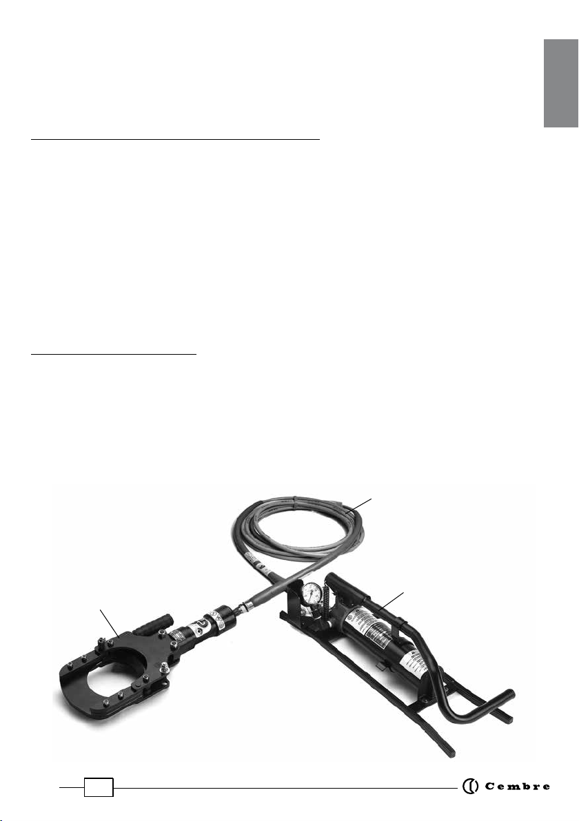
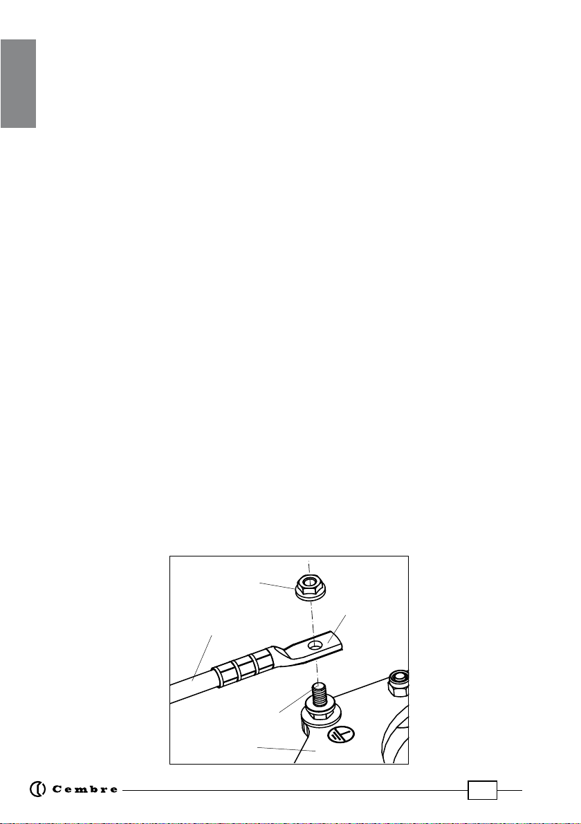
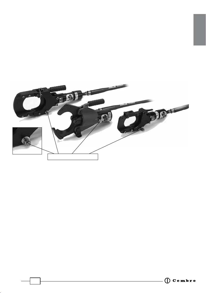
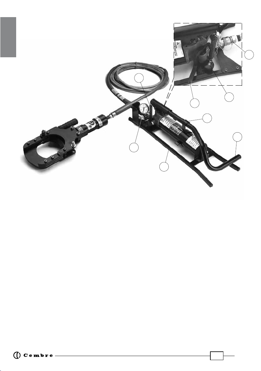
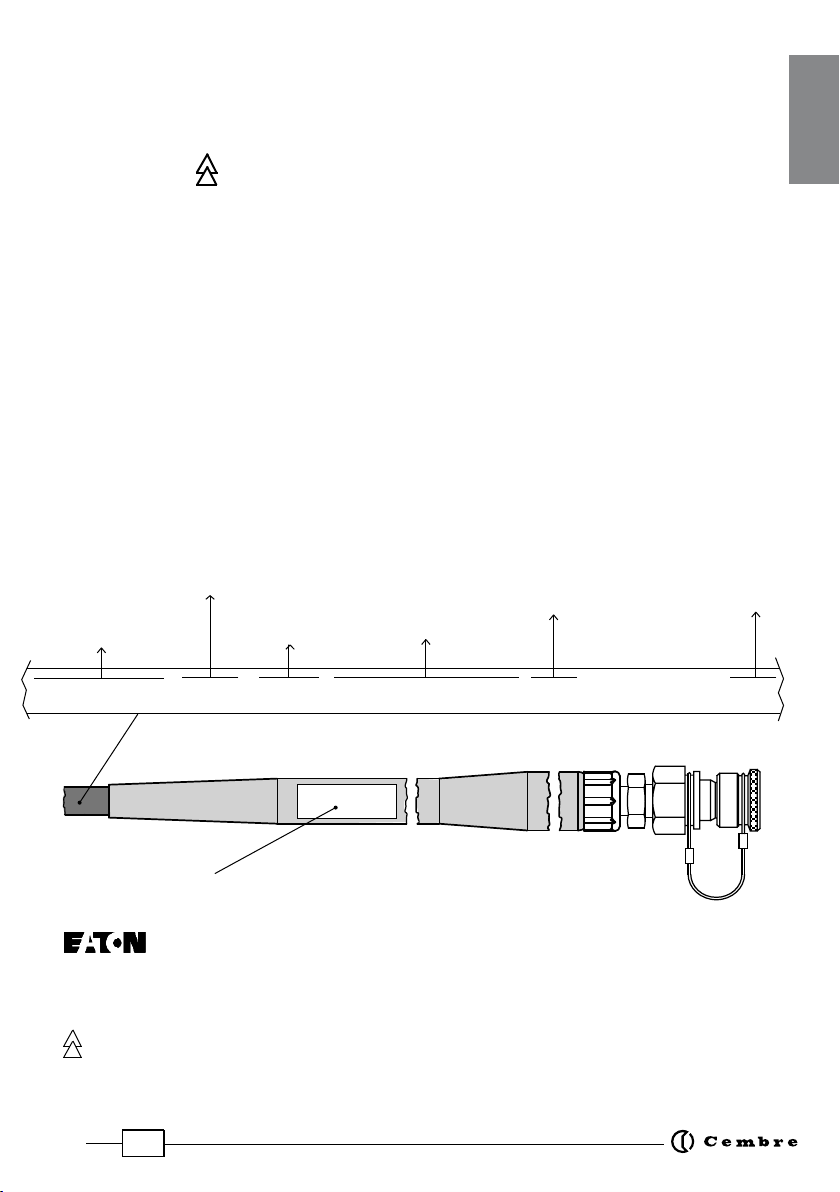
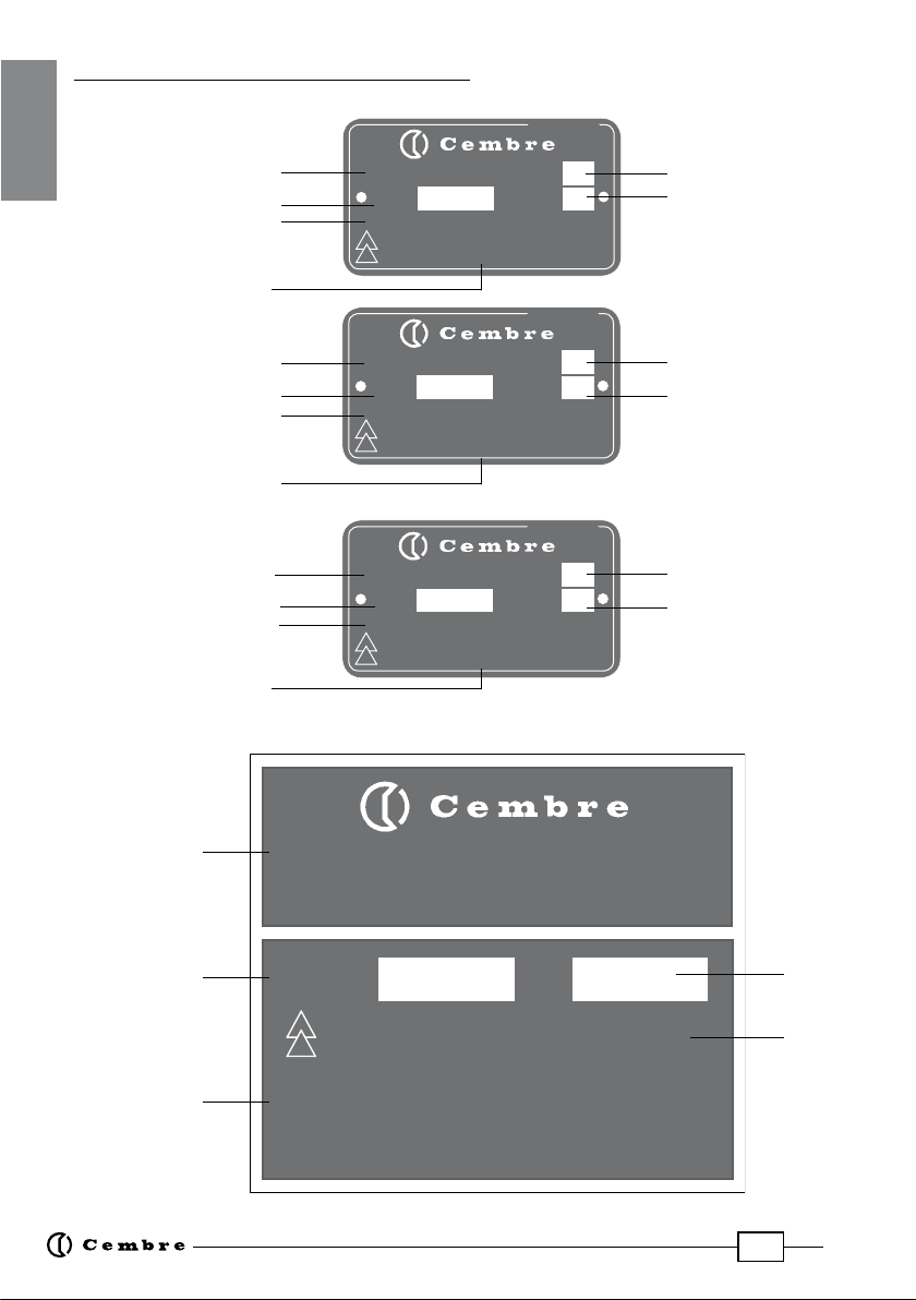
2. Description of device .................................................................................................................................. 2
3. Technical date ................................................................................................................................................ 8
4. Storage and transportation ...................................................................................................................... 9
5. Preliminary phases ....................................................................................................................................... 9
6. Cutting procedure ....................................................................................................................................... 9
7. In case of breakdown ................................................................................................................................ 11
8. Care and maintenance ............................................................................................................................. 13
9. Return to
Cembre
for overhaul ........................................................................................................14
INDEX
1. Emploi conforme aux normes ............................................................................................................... 15
2. Description du dispositif ......................................................................................................................... 15
3. Données techniques ................................................................................................................................. 21
4. Transport ....................................................................................................................................................... 22
5. Phases préliminaires ................................................................................................................................. 22
6. Procédure de coupe .................................................................................................................................. 22
7. Comportement en cas d'anomalie ...................................................................................................... 24
8. Conservation et entretien ....................................................................................................................... 26
9. Envoi en revision à
Cembre
............................................................................................................. 27
INDEX
1. Gebruik volgens de normen .................................................................................................................. 28
2. Beschrijving van de veiligheidsknipset .............................................................................................. 28
3. Technische gegevens ................................................................................................................................ 34
4. Transport ....................................................................................................................................................... 35
5. Inleidende fasen ......................................................................................................................................... 35
6. De knip procedure ..................................................................................................................................... 35
7. Gedrag in geval van onregelmatigheden ......................................................................................... 37
8. Verzorging en onderhoud ...................................................................................................................... 39
9. Teruggave aan
Cembre
voor revisie ............................................................................................. 40
INDICE
1. Utilización conforme con las normas .................................................................................................. 41
2. Descripción del dispositivo .................................................................................................................... 41
3. Datos técnicos ............................................................................................................................................. 47
4. Transporte ..................................................................................................................................................... 48
5. Fases preliminares ...................................................................................................................................... 48
6. Procedimiento de corte ........................................................................................................................... 48
7. Comportamiento en caso de anomalías ............................................................................................ 50
8. Cuidado y mantenimiento ...................................................................................................................... 52
9. Devolución a
Cembre
para revisiones ......................................................................................... 53
INDICE
1. Utilizzo conforme alle norme ................................................................................................................. 54
2. Descrizione del dispositivo ..................................................................................................................... 54
3. Dati tecnici .................................................................................................................................................... 60
4. Trasporto ....................................................................................................................................................... 61
5. Fasi preliminari ............................................................................................................................................ 61
6. Procedura di taglio .................................................................................................................................... 61
7. Comportamento in caso di anomalie ................................................................................................. 63
8. Cura e manutenzione ............................................................................................................................... 65
9. Resa alla
Cembre
per revisione ...................................................................................................... 66
ENGLISH
FRANÇAIS
NEDERLANDS
ESPAÑOL
ITALIANO
Pag. / Blad

3
Cutting head
Flexible insulated hose
PumP
?
BEFORE USING THE INSULATED CABLE CUTTING UNITS, READ THE FOLLOW INSTRUCTIONS.
VITAL TECHNICAL SAFETY INFORMATION IS SHOWN BY IN THE LEFT MARGIN.
1. USE IN COMPLIANCE WITH THE REGULATIONS
These insulated cable cutting units can be used to safely cut copper and aluminium cables with
nominal voltage up to 60 kV, where the absence of voltage cannot be guaranteed.
These units can be use both indoors and out, even in wet conditions when the temperature is
between -20°C and +40°C.
Do not cut cables with special armour (e.g. cables for wells, self-bearing overhead cables, marine
cables etc.).
2. DESCRIPTION OF DEVICE
The cable cutting units comprise the following components:
– Cutting head
– Flexible insulated hose
– Insulating oil
– Pedal pump
– Earthing device
Fig. 1 - Cutting unit components
ENGLISH

4
2.1) Equipotential connection and earthing system
2.1.1) Earthing the pump
Between the pump and earth there must be a connection with an earth conductor.
For this purpose a Cembre earth cable must be used.This earthing device is availble as an optional
accessory (Part. no EK 100).
One end of the earth cable must be connected to the earth terminal of the pump, the other end
must be connected to the surrounding environmental potential (e.g. grate, steel sheet, etc.).
2.1.2) Earthing the cutting head
In Germany (see BGI 845) no earth conductor must be connected to the cutting head.
In some European countries, the earth connection is used to favour the intervention of single phase
short circuit protective devices.
For countries other than Germany contact the electricity supply utility.
Should it be needed, the earthing device, comprising a 5m long cable and an earth rod, may be
ordered from Cembre (Part. no EK 500P).
Whatever the case, the earthing device must be approved by Cembre.
For earthing the cutting head, proceed as follows:
– Unscrew the nut of the earth terminal on the head.
– Connect the 5 m earth cable to the cutting head and tighten the nut.
– Tighten the nut hard.
– Fully unwind the earth cable.
– Ram the earth rod deep into solid ground.
– Connect the cable to the earth rod and tighten the nut of the cable terminal.
nut
earthing
terminal
earth Cable
(5 meters)
Cutting head
Cable lug
`
ENGLISH

5
2.2) Cutting head
The cutting head must be positioned manually around the cable to be cut based on the diameter
of the cable which has to be cut.
Select the appropriate cutting head for the diameter of the cable to be cut and use only with the
associated pump (see text).
To guarantee a permanent connection and resistance to the pressure developed in the system, the
flexible hose is screwed directly to the cutting head by means of a coupling which can be loosened
only by using a tool.
The cutting head is provided with an earth terminal (see figure).
2.3) Flexible insulated hose
The flexible insulated hose is used to deliver oil under pressure, generated by the pump, to the
cutting head and as an insulating element between the head and the pump.
It comprises a flexible insulated hose and connectors applied to each end.
The flexible insulated hose is completely filled with insulating oil.
2.4) Insulating oil
The insulating oil transmits the operating pressure of the pump to the cutting head. It is a special
hydraulic oil with properties which insulate the pump from the cutting head.
2.5) Quick couplers
Theflexible insulatedhose isfittedwith aquick connectorforconnection tothepump without tools.
This coupling cannot be disconnected if the system is under pressure.
The anti-dust protection cap must be used on both hose and pump couplings to prevent ingress
of dirt or contamination.
earth terminal
TC 120-W...
TC 096-W...
TC 086-W...
ENGLISH

6
05
06
04
01
02
03
07
08
2.6) Pump
The operating pressure required for cutting the cable is
generated in the pump.
The pump is operated by means of a foot pedal.
Fig. 2 - Pump components
01 - Pump base 05 - Pedal return spring
02 - Oil discharge lever 06 - Manometer
03 - Operating pedal 07 - Earth connection terminal
04 - Pedal block support 08 - Hydraulic quick coupler
The oil discharge pedal enables the return of the insulating oil to the pump tank and is used to open
the blades of the cutting head on termination of the cutting operation.
The manometer shows the operating pressure present in the system.
The pressure field with red background represents the maximum acceptable overpressure operat-
ing limit which cannot be exceeded.
On reaching the maximum allowed operating pressure, the maximum pressure valve inside the
pump stops any further increase in pressure.
The earth connection terminal on the base of the pump enables the connection of an earthing
cable. To avoid the danger of tension gradients, the pump must be connected to the environment
potential (grate, steel sheet, etc.).
ENGLISH

7
2.7) Markings
Cuttinghead, flexible insulated hose and pump must be providedwith wording which enables both
clear identification and the correct correlation of cable cutting unit components.
The marking 60000 V indicates that the device is suitable for use on cables with voltage
up to 60 kV.
Permissible Operating pressure: 625 bar
The pressure of 625 bar is not exceeded in the use of the cable cutting units.
On the cutting head
Maximum diameter of the cable permissible: 85 mm, 95 mm, 120 mm (according to type; see
technical data).
Cables with external diameters up to the indicated values can be cut regularly.
On the flexible insulated hose
Repeated every 50 cm:
On the guards hose:
– (guard hose manufacturers mark)
– 10 / 30465 (manufactured year / laboratory test nr.)
–Q.C. AVR.10 (quality control; manufactured date month. year)
– 630 bar (permissible operating pressure)
– 60 kV (equipment suitable for working on cables under voltage up to 60 kV)
hose
manufacturer
type of flexible insula-
ted hose
rated
diameter
Max.
pressure
in PSI
and BAR
quarter and year
manufactured serial Nr.
EATON SYNFLEX®3VE0-03 3/16" I.D. W.P. 10000 P.S.I. (690 BAR) (4Q09) NON CONDUCTIVE 144388
?
ENGLISH

8
85
PO6000-WZ-KV
Benutzen
mit Pumpe
Serien-
Nr.
TC086-WZ-1000-KV
Typ
Kabel. Ø
Max. mm
Jahr
625 bar
Made in Italy
60000 V
Zugelassener Höchstdruck
95
PO6000-WZ-KV
Benutzen
mit Pumpe
Serien-
Nr.
TC096-WZ-1000-KV
Ty p
Kabel. Ø
Max. mm
Jahr
625 bar
Made in Italy
60000 V
Zugelassener Höchstdruck
120
PO6000-WZ-KV
Benutzen
mit Pumpe
Serien-
Nr.
TC120-WZ-1000-KV
Ty p
Kabel. Ø
Max. mm
Jahr
625 bar
Made in Italy
60000 V
Zugelassener Höchstdruck
PO6000-WZ-KV
DOPPELKOLBENHYDRAULIK FUSSPUMPE TYP
625 bar
Serien-Nr. Jahr
Zugelassener
Höchstdruck
TC086-WZ-1000-KV
TC096-WZ-1000-KV
TC120-WZ-1000-KV
Erlaubte
Schneidköpfe
Made in Italy
60000 V
Type
Serial Nr.
Maximum permissible
pressure
Year
Maximum diameter
of cable
Cutting heads
to be connected
Serial Nr.
TWO SPEED
HYDRAULIC
FOOT PUMP
Type
Serial Nr.
Year
Maximum diameter
of cable
Type
Serial Nr.
Year
Maximum diameter
of cable
Year
Pump to be used
DATA INDICATED ON THE METAL LABELS:
Pump to be used
Pump to be used
Maximum permissible
pressure
Maximum permissible
pressure
Maximum
permissible
pressure
ENGLISH

9
Maximum
permissible
pressure
3. TECHNICAL DATE
Foot pump:
Type Manufacturer
Maximum
permissible
pressure
(bar)
Oil
reservoir
capacity
(cm3)
Weight
(kg)
Length
(mm)
Width
(mm)
Height
(mm)
Cembre 625 1000 9,7 680 200 163
Flexible insulated f hose:
Type Manufacturer Insulated
hose
type
Nominal
diameter
(inch)
Total
length
(m)
>10
Permissible
pressure
(bar)
Insulating oil:
Type
Density
to 15°C
(kg/m3)
DIEKAN 1640 853
Manufacturer
TOTAL
Melting
point
(°C)
- 33
Flash
point
(°C)
174 12,8
Viscosity
to 40°C
(mm2/s)
Cutting head:
Type
TC086-WZ-1000-
KV
Manufacturer
Maximum
permissible
pressure
(bar)
Weight
(kg)
Max.
cutting
diam.
(mm)
Length
(mm)
Width
(mm)
Oil
volume
(cm3)
TC096-WZ-1000-
KV
TC120-WZ-1000-KV
Cembre
Cembre
Cembre
625
625
625
89,57
123,8
181,5
6,9
9,3
10,5
85
95
120
369,5
394,0
481,5
135
242
175
Metal case
Type
Weight
(kg)
Dimensions
(mm) LxWxH
VAL CP096-W 12,6 786 x 430 x 175
PO6000-WZ-KV
In the case of accidental oil leak, collect the oil using sand or earth and dispose of only in accordance with
local regulations.
SYNFLEX EATON 3VE0-03 3/16 630
ENGLISH

10
4. STORAGE AND TRANSPORTATION
Each Cembre insulated cable cutting unit is precisely constructed and supplied in a robust case
for protection of individual components from damage and transportation to the work place.
Only remove a cable cutting unit from its case at the work place.
5. PRELIMINARY PHASES
The cable cutting units must be used as described herein and always observing DIN VDE 0105-100.
– Only remove a cable cutting unit from its case at the work place.
– Check all components (cutting head, flexible insulated hose, couplings and pump) before
use to verify there is no evident damage:
ëCutting edges of the blades damaged ?
ëFlexible insulated hose clean and without visible damage ?
ëQuick couplings clean ?
ëManometer functioning ?
ëPump pedal easy to operate ?
ëDischarge lever enables oil return ?
– A protected zone must be established within a 10m radius around the work place where entry
is forbidden.
6. CUTTING PROCEDURE
Insulated cable cutting units must be earthed in accordance with national standards (e.g. BGI 845
ZH1/437).
The correct cutting procedure is as follows:
– Contact the electricity supply utility.
– Using the grips provided, carry the cutting head to the cable to be cut.
– Position the blades of the cutting head around the cable to be cut and stabilise its position
(e.g. by pressing the cutting head against the ground or for the TC096-WZ-1000-KV by turning
the special support).
When cutting single pole cables, all three phases must be cut simultaneously by the head.
?
ENGLISH

11
– Fully unwind the flexible insulated hose.
– Position the pump as far as possible from the cutting point and connect it to the flexible insulated
hose.
– Place the pump such that the flexible insulated hose can be laid“zigzag”on the ground.
This precaution is to compensate for shortening of the hose while the pump is operating.
– Ifforanyreasonthe minimum 10mradiusno entry zonecannotbe established,other precautionary
measures must be taken (e.g. embankments or protection walls) to protect the operator from a
possible disturbance arc due to a short circuit.
– Should there be the danger of voltage gradients between cutting head and pump, the pump
can be connected to earth using the earth terminal and the specific cableso as to form an equi-
potential connection.
– Contact the electricity supply utility.
– Check that nobody enters the danger zone.
– Carry out the cutting operation by operating the pump pedal.
Position the foot in the centre of the pedal crank.
During operating of the pump, check pressure on the manometer.
– During the cutting operation there is a slow increase in pressure which can vary depending on
the type of cable.
– It is necessary to continue to use the pump until the maximum permissible over pressure
is reached and the safety valve is heard to click into action.
– Operate the oil discharge lever of the pump and keep it pressed for about 60 seconds so that the
blades of the cutting head can automatically return to the start position.
– Inform the electricity supply utility that the cutting operation has been carried out.
If they do not warn against any particular events, the cutting zone can be accessed.
– Access the cutting area and remove the cutting head from the cable using the support grip
provided.
?
?
?
ENGLISH

12
– Push the pump pedal downwards and block it in the low position using the support block.
– Operate the oil discharge lever until the blades on the cutting head are fully open (lack of pres-
sure).
– Disconnect the flexible insulated hose from the pump using the quick coupling.
– Clean the quick couplings and close the protection covers.
– Dry the pump and clean it with a cloth. Place the pump in its case and block it in the special
restraints to avoid it slipping.
– Dry the cutting head and the flexible insulated hose and clean it thoroughly using a cloth.
– Place the cutting head in the side compartment of the transport case.
Make sure the hose is not bent when the cutting head is placed in the case.
– Wind up the flexible insulated hose in the transport case with ample loops around the pump and
cutting head.
– Make sure this instruction manual is present in the transport case.
7. IN CASE OF BREAKDOWN
Due to unforeseen circumstances the cutting operation could not be completed or terminated as
described in section 6. In such cases special precautions must be taken, including:
– Unintentional cutting of live cable.
– Following a short circuit, contact the electricity supply utility immediately for information.
– Continue to operate the pedal of the pump until the maximum pressure valve intervenes.
– Operate the oil discharge lever for 60 seconds to make the blades return to the start position if
the damage caused by the short circuit is not too serious.
– Contact the electricity supply utility for further information.
– Access the cutting area and remove the cutting head from the cable using an insulating rod.
– Return the cable cutting unit to Cembre for test and repair (see point 8).
ENGLISH

13
– While pump is operating there is no increase in pressure on the manometer.
– Check to make sure the oil discharge lever is not pressed.
– Operate the oil discharge lever briefly several times and check if after operating this immediately
returns to the start position.
– Check to see if there is sufficient insulating oil in the pump (remove the top-up cover of the tank).
– Add insulating oil if needed (use only TOTAL DIEKAN 1640 oil).
– Although the safety valve has triggered and the maximum operating pressure has been
reached, the cable has not been completely cut.
– Move away from the zone immediately.
– Contact the electricity supply utility immediately for information.
– Operate the oil discharge lever for 60 seconds.
– Remove the head from the cable using an insulating rod.
– Accurately check the cutting head (e.g. condition of blades; fittings); possibly carry out a “free
run”.
– If the electricity supply utility has not given specific instructions, move the cable cutting unit to
a dfferent point and carry out the cutting operation again.
– While the pump is functioning there is a leakage of insulating oil.
– Immediately stop pumping.
– Operate the oil discharge lever for 60 seconds until the insulating oil in the system returns to the
tank and the blades of the cutting head can open.
– Should the cable be under voltage, inform the electricity supply utility immediately.
– If the absence of voltage cannot be affirmed with absolute certainty, remove the cutting head
from the cable using an insulating rod.
On no account touch the cutting head with the hands or conductive objects!
– If the cable has to be cut even though it is under voltage, carry out the operation with another
device that is known to function correctly.
– If the oil leaks from the screwed coupling of the hose, this can be tightened.
– If the fault is not removed, the cable cutting units must be sent to Cembre to be tested and
repaired.
ENGLISH

14
8. CARE AND MAINTENANCE
The Cembre insulated cable cutting units are designed for on site use and thanks to its construc-
tion characteristics it is a technical and robust operating device.
To guarantee the reliability of the device for a long period, the following instructions must be
complied with:
– Regularly remove dirt (depending on how often it is used) from the cutting head, cylinder, blades
and seals using a brush dipped in a liquid detergent. Dry the area carefully.
– Carefully clean the quick couplings and their protection covers each time the unit is used.
– Clean the anchoring screws of the pedal; the pin and blade guide of the cutting head must be
lubricated with a few drops of oil, to avoid seizing if it is used continuously.
– Every 6 months check the oil level in the tank and if necessary top up.
Oil top up
– Position the pump on a gradient so that the air collects at the filler in put hole and the oil is able
to enter freely.
– Release the pedal to make the tank cap easier to access.
– Remove the cap and pour in the oil.
The oil must reach the bottom of the threading of the hole in
the tank.
– Close the oil tank with the cap.
The pump is ready for use again.
Reservoircap
When topping up always
use the oil specified in
point 3.
Never top up with old or
used oil.
The oil must be clean.
OIL
Öl
~ 250 mm
ENGLISH

15
– To remove any deposits in the oil circuit, the flexible insulated hose must be disconnected from
the pump. Operate the oil discharge pedal and at the same time press the main pedal twice. In
this way the pump oil ducts are cleaned.
– Change the oil at the maintenance intervals, registering the date the oil is changed.
For this purpose the cable cutting units must be sent, complete, to Cembre or to personnel
authorised by Cembre.
Cembre will change the oil and at the same time carry out an “Inspection”.
– Damaged parts can only be replaced by original Cembre spare parts.
– Substitution of individual parts can only be carried out by personnel authorised by Cembre.
– To exclude hidden faults following maintenance or repairs on the cable cutting units, these
operations must be carried out by Cembre or by personnel authorised by Cembre.
– For all maintenance and repairs carried out on the cable cutting units, the person who carried
them out is responsible. If changes to the product are made so that it is no longer identical to
the certified finished product (e.g. failure to use original spare parts), the authorisation to use the
GS trademark shall be lost.
– Cembre recommends having maintenance carried out by trained personnel.
Maintenance must be carried out at the following intervals:
6 years – occasional use - example: about 6 times a year.
4 years – normal use - example: about 12 times a year.
2 years – frequent use - example: more than once a month during the year.
Caution: Maintenance carried out by trained personnel is, according to BGVA 3, absolutely neces-
sary at the latest aafter 6 years disregarding the frequency of use.
– To replace the hydraulic hoses follow the instructions of BG nr. BGR 237 regulation.
In the case of disposal, the device with its contents (insulating hydraulic oil) must be dealt with
only in accordance with local regulations.
9. RETURN TO Cembre FOR OVERHAUL
In the case of a breakdown contact our Area Agent who will advise you on the problem and give
you the necessary instructions on how to dispatch the tool to our nearest service Centre; if possible,
attach a copy of theTest Certificate supplied by Cembre together with the tool or fill in and attach
the form available in the“ASSISTANCE”section of the Cembre website.
ENGLISH

16
tête de CouPe
Flexible isolant
PomPe aPedale
Fig. 1 - Elements de l'unité
AVANT D'UTILISERLE COUPECÂBLESISOLE,LIREATTENTIVEMENT LES INSTRUCTIONS D'UTI
LISATIONS SUIVANTES.
LES RENSEIGNEMENTS PARTICULIÈREMENT IMPORTANTS POUR LA SÉCURITÉ SONT MIS EN
ÉVIDENCE PAR UN SYMBOLE INSCRIT DANS LA MARGE DE GAUCHE.
1. EMPLOI CONFORME AU NORMES
Le coupe-câble portable sert à couper en toute sécurité les câbles en cuivre et en aluminium sus-
ceptibles d’être accidentellement sous une tension nominale de 60 kV maxi.
Le dispositif peut être utilisé aussi bien au couvert qu'à l'air libre, même en présence de précipita-
tions, dans une fourchette de températures comprise entre -20°C et +40°C.
Il n'est pas possible de couper des câbles à enveloppe extérieure spéciale (par ex. câbles pour puits,
câbles aériens autoporteurs, câbles marins, etc.).
2. DESCRIPTION DU DISPOSITIF
Le coupe-câbles comprend essentiellement les composants suivants:
– Tête de coupe
– Flexible isolant
– Huile isolante
– Pompe à pédale
– Dispositif de mise à la terre
?
FRANÇAIS

17
2.1) Branchement équipotentiel et système de mise à la terre
2.1.1) Mise à la terre de la pompe
Prévoir une connexion avec un conducteur de terre entre la pompe et la terre.
Employer à cet effet le conducteur de terre prévu par Cembre. Ce dispositif de mise à la terre est
disponible sur demande comme accessoire (Réf. n° EK 100).
Une extrémité du conducteur de terre doit être branchée à la borne de terre de la pompe, l'autre
extrémité doit être branchée au potentiel du milieu environnant (par ex. grille, tôle d'acier, etc.).
2.1.2) Mise à la terre de la tête de coupe
En Allemagne (voir BGI 845), aucun conducteur de terre ne doit être relié à la tête de coupe. Dans
certains pays européens,la mise à la terre est utilisée pour favoriserle déclenchementdesdispositifs
de protection pour les courts-circuits monophasés.
Pour les pays autres que l'Allemagne, s'adresser au gestionnaire du réseau électrique.
En cas de besoin, le dispositif de mise à la terre est composé par un conducteur de 5 m et par un
déperditeur de terre et peut être demandé à Cembre (Réf. n° EK 500P).
Utiliser toujours le dispositif de mise à la terre approuvé par Cembre.
Pour la mise à la terre de la tête de coupe, procéder de la manière suivante:
– Dévisser l'écrou de la borne de mise à la terre sur la tête.
– Brancher le câble de terre de 5 m à la tête de coupe et le bloquer à l'aide de l'écrou.
–Serrer à fond l'écrou.
– Dérouler complètement le conducteur de terre.
– Enfoncer à fond le déperditeur de terre dans le sol.
– Connecter le câble au déperditeur de terre en serrant à fond la cosse à l'aide de l'écrou corres-
pondant.
eCrou
borne de mise
ala terre
ConduCteur de terre
(5 metres)
tête de CouPe
Cosse
`
FRANÇAIS

18
2.2) Tête de coupe
Placer manuellement la tête de coupe autour du câble à couper en fonction du diamètre de celui-ci.
Choisir la tête de coupe appropriée. La tête de coupe ne doit être utilisée qu'avec la pompe cor-
respondante (voir mention).
Pour assurer une connexion permanente et résistante à la pression développée par le système,
le flexible a été vissé directement à la tête de coupe à l'aide d'un joint qui ne peut être desserré
qu'avec un outil.
La tête de coupe est munie d'une borne de mise à la terre (voir figure).
2.3) Flexible isolant
Le flexible isolant sert à envoyer à la tête de coupe l'huile sous pression générée par la pompe et
joue le rôle d'élément isolant entre la tête et la pompe. Le dispositif est composé par un flexible
isolant et deux éléments de raccordement appliqués à chaque extrémité.
Le flexible isolant est rempli complètement d'huile isolante.
2.4) Huile isolante
L'huile isolante assure la transmission de la pression de service de la pompe à la tête de coupe. Il
s'agit d'une huile hydraulique spéciale possédant des propriétés isolantes qui isole la pompe et la
tête de coupe l'une de l'autre.
2.5) Raccorde rapide à blocage automatique
L'élément de raccordement à la pompe est réalisé moyennant un raccord rapide à blocage auto-
matique et peut être branché à la pompe ou débranché sans outil.
Cet raccord ne peut pas être débranché si le système est sous pression. Les bouchons de protection
antipoussière doivent être montés sur les raccords correspondants de la pompe et de la tête afin
d'empêcher la pénétration de corps étrangers et de particules de saleté.
borne de mise ala terre
TC 120-W...
TC 096-W...
TC 086-W...
FRANÇAIS

19
05
06
04
01
02
03
07
2.6) Pompe
Dans la pompe est générée la pression de service nécessaire
pour la coupe du câble.
L'opérateur actionne la pompe en agissant sur la pédale.
Fig. 2 - Elements de la pompe
01 - Embase de la pompe 05 - Ressorts de rappel de la pédale
02 - Pédale d'évacuation de l'huile 06 - Manomètre
03 - Pédale de actionnement 07 - Borne pour la connexion équipotentielle
04 - Blocage de la pédale 08 - Élément de raccordement (raccord rapide)
La pédale d'évacuation de l'huile autorise le retour de l'huile isolante dans le réservoir de la pompe;
en l'actionnant, on valide l'ouverture de la tête de coupe à la fin de l'opération de coupe.
Le manomètre indique la pression présente dans le circuit.
La plage de pression à fond rouge représente la plage limite de la surpression de service maximum
admise qui ne peut pas être dépassée.
Quand le système atteint la pression de service maximum admise, la soupape de surpression à
l'intérieur de la pompe empêche l'augmentation ultérieure de la pression.
La borne pour la connexion équipotentielle sur l'embase de la pompe permet de brancher un
conducteur de terre. Pour prévenir le danger de gradients de tension, la pompe doit être branchée
au potentiel du milieu environnant (grille, tôle d'acier, etc.).
08
FRANÇAIS

20
2.7) Mentions et leur signification
La tête de coupe, le flexible isolant et la pompe doivent être munies d'indications permettant
d'identifier clairement les éléments du coupe-câbles et leur corrélation.
L'estampille 60000V indique que le dispositif est apte à l'utilisation sur des composants
sous tension jusqu'à 60 kV.
Pression de service admise: 625 bar
La pression de 625 bar n'est pas dépassée lors de l'emploi du coupe-câbles.
Sur la tête de coupe
Diamètre du câble maxi. admis: 85 mm, 95 mm, 120 mm (selon le type; voir données techniques).
Les câbles de diamètre extérieur jusqu'à la valeur indiquée peuvent être coupés régulièrement.
Sur le flexible isolant
Marquage continu à distance de 50 cm sur le flexible isolant:
Marquage sur les extrémité du flexible isolant:
– (fabricant les extrémité du flexible isolant)
– 10 / 30465 (année de fabrication / test de laboratoire)
–Q.C. AVR.10 (contrôle de la qualité; date de fabrication mois. année)
– 630 bar (pression de service admise)
– 60 kV (appareil apte à travailler sur des éléments sous tension jusqu'à 60 kV)
fabricant du
flexible isolant
type de
flexible isolant
diamètre nominal
Max.
pression
en PSI
et BAR
trimestre et année
de fabrication N° de série
EATON SYNFLEX®3VE0-03 3/16" I.D. W.P. 10000 P.S.I. (690 BAR) (4Q09) NON CONDUCTIVE
144388
Non conductive
?
FRANÇAIS
This manual suits for next models
2
Table of contents
Languages:
Other Cembre Tools manuals

Cembre
Cembre B-FL750ND User manual

Cembre
Cembre HTEPE.DET10 User manual

Cembre
Cembre HT-FL75 User manual

Cembre
Cembre B68RC3-85 User manual

Cembre
Cembre TC050Y User manual

Cembre
Cembre PNB-1 User manual

Cembre
Cembre RHM50 User manual

Cembre
Cembre HP1 User manual

Cembre
Cembre RHM132 User manual

Cembre
Cembre RHU240-3D-850 User manual

Cembre
Cembre TC04 User manual

Cembre
Cembre HT131LN-C User manual

Cembre
Cembre TC096 User manual

Cembre
Cembre CMB3 Parts list manual

Cembre
Cembre RHTD1724 User manual

Cembre
Cembre ht51 User manual

Cembre
Cembre TC085 User manual

Cembre
Cembre MT-FC48N User manual

Cembre
Cembre TC096 User manual

Cembre
Cembre HT-TRC Operating instructions