manuals.online logo
Brands
  1. Home
  2. •
  3. Brands
  4. •
  5. Connects2
  6. •
  7. Automobile Accessories
  8. •
  9. Connects2 CTSPO007.2 User manual

Connects2 CTSPO007.2 User manual

CTSPO007.2
Steering Wheel Control
Interface for Porsche Vehicles
APPLICATION
FEATURES
Porsche Panamera 2009 - 2016
Porsche Macan (95B) 2014 - 2016
Porsche Cayenne 2011 - 2016
• Retains Factory Steering Wheel Control Functionality
• Retains Factory Phone Button Functionality
• Retains MOST 25 Fiber Amplied System
• Retains USB and AUX Inputs
• Retains Reversing Camera
• Retains Parking Sensor Audio
• Provides Outputs for Park Brake, Reverse Gear, Speed Pulse, Mute & Amp Remote
• Updateable via USB (contact supplier for more information)
The information provided in this document is subject to change without notice due to manufacturer changes and/or improvements to the product/s. This
instruction manual is based on documented data and research. The manufacturer of this product cannot be held responsible for any changes made to the
vehicle by the manufacturer or damages that may occur through the installation of this product in accordance with the steps outlined herein.
Note: Application data is subject to change at any time
DISCLAIMER
For ber-amplied vehicles with MOST 25 systems and quadlock connectors.
CTSPO007.2_IG_en-GB_v1
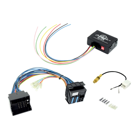
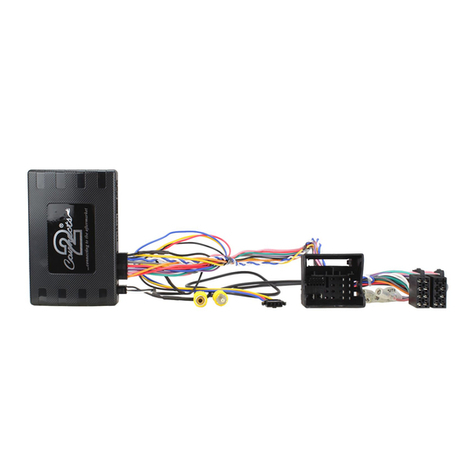
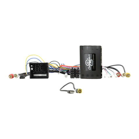
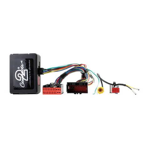
i. Interface Box
ii. ISO Connector (16 Pin)
iii. Quadlock Connector (40 Pin)
iv. RCA Amplier (Red/White)
v. RCA AUX (Red/White)
i
ii
iiiiv vi
vvii
viii
vi. RCA Camera (Yellow)
vii. Flying Wires
viii. USB Retention Harness
ix. Amp Retention Interface
ix
2CTSPO007.2_IG_en-GB_v1
PRIOR TO INSTALLATION
Read the manual prior to installation. Technical knowledge is necessary for installation. The place of installation
must be free of moisture and away from heat sources. Please ensure that the correct tools are used during the
installation to avoid damage to the vehicle or product. Connects2 can not be held responsible for the installation
of this product.
Note: The aftermarket stereo being installed must have female RCA connectors in order for this product to
function correctly
IN ISO CONNECTOR
Purple Right Rear Speaker +
Purple/Black Right Rear Speaker -
Green Left Rear Speaker +
Green/Black Left Rear Speaker -
Grey Right Front Speaker +
Grey/Black Right Front Speaker -
White Left Front Speaker +
White/Black Left Front Speaker -
ADDITIONAL CONNECTIONS
Pink Speed Pulse
Green Park Brake
Purple/White Reverse Gear
Blue/White Amp Remote
Grey Mute
WIRING KEY
STEERING WHEEL CONTROL FUNCTIONALITY
The following diagram, though based on careful research, is an example only
Individual steering wheel control congurations may differ.
Yellow Permanent 12V
Black Ground
Red Ignition 12V
Orange Illumination
1
2
4
5
1. Volume Up (Scroll Up)
Volume Down (Scroll Down)
Mute (Push)
2. Source
3. Pick Up
3
4. Track Up (Scroll Up)
Track Down (Scroll Down)
Band (Push)
5. Hang Up
Red/White RCA (AUX) AUX Input Retention
Red/White RCA (Speaker) Amplier/Audio Retention
Yellow RCA Reversing Camera Retention
3
Need help? Visit support.connects2.com/tickets/technical
CTSPO007.2_IG_en-GB_v1
INSTALLATION GUIDE
Before installing the interface, the factory stereo must be removed and disconnected. To do this, please consult
the vehicle owner’s manual/handbook or contact a tting professional.
A stereo connection (patch) lead is also required for the installation of this interface (supplied seperately).
Please ensure that you have the correct lead before proceeding. For universal patch leads, prepare the wiring
loops in accordance with the instruction manual supplied with the product before installation.
1. Connect the 12 Pin connector from the stereo connection (patch) lead to the interface box
See wiring diagram on Pg.4 for more information
2. Connect the opposite end of the stereo connection (patch) lead to the steering wheel control input on
the back of the aftermarket stereo
NOTE: This may be a 3.5mm jack connector or a wired input depending on the brand of aftermarket stereo being tted. Please consult the
aftermarket stereo installation manual for further information on where to make the connection
IMPORTANT: THIS STEP MUST BE COMPLETED BEFORE CONNECTING POWER TO THE INTERFACE.
FAILURE TO DO SO MAY RESULT IN A LACK OF FUNCTIONALITY AND THE NEED TO REINSTALL THE
PRODUCT
!
3. Connect the 14 Pin connector from the supplied wiring loom to the interface box
6. Connect the power/speaker ISO connector to the power/speaker ISO connector at the rear of the
aftermarket stereo.
NOTE: For aftermarket stereos which do not have an ISO connector, please see “Wiring Key” on Pg.2 for information on which wires to
connect. Some interfaces may also have additional ‘flying’ wires which can be connected to the vehicle to support various features
ie. parking brake trigger, reverse gear and speed pulse. Details of these can be found under ‘Additional Connections’.
11. Connect the quadlock connector on the supplied harness to the quadlock connector from the vehicle
12. Test stereo and steering wheel control functionality for correct operation before reassembling the
vehicle dashboard. If steering wheel control functions are unresponsive, please uninstall the interface and
wiring and reinstall carefully in accordance with the above steps.
For further help and support, please contact us directly at support.connects2.com/tickets/technical and ll out a
support ticket with the full details of your issue.
4. Connect the amplier retention interface to the 8 Pin connector on the supplied wiring loom
5. Remove the plastic dust cover from the amplier retention interface and plug in the vehicle’s ber
amplier connection
7. Connect the male red and white RCA connectors (speaker) to the front line outputs on the rear of the
aftermarket stereo to retain vehicle amplier audio
9. Connect the yellow RCA connector to the vehicle’s pre-existing camera input to retain the factory
reversing camera
10. Connect the USB retention harness to the vehicle and to the back of the aftermarket stereo to retain
the OEM USB input
8. Connect the male red and white RCA connectors (AUX) to the rear of the aftermarket stereo to retain the
OEM AUX input

4CTSPO007.2_IG_en-GB_v1
WIRING DIAGRAM
ISO Connector
Connect to aftermarket stereo
Quadlock Connector
Connect to quadlock connector from vehicle
Stereo Connection (Patch) Lead Connector [12 Pin]
Connect to Interface Box
Note: Must be connected first, before power
connection is made to the interface
Main Wiring Loom Connector [14 Pin]
Connect to Interface Box
Interface Box
Fiber Amplifier Connector
Firstly remove dust cover
from interface
Then connect fiber
amplifier connection
from vehicle
to interface
White/Red RCA Connectors (AUX)
Connect to aftermarket stereo
Flying Wires
Pink - Speed Pulse
Green - Park Brake
Purple/White - Reverse Gear
Blue/White - Amp Remote
Grey - Mute
Male Yellow RCA Connector
Connect to factory camera input
AUX
SPKR
White/Red RCA Connectors (Speaker)
Connect to front line output of aftermarket stereo
USB Retention Lead
Connect to vehicle Connect to aftermarket stereo

Other Connects2 Automobile Accessories manuals

Connects2 CAM-61 User manual

Connects2

Connects2 CAM-61 User manual

Connects2 CTSHU002.2 Assembly instructions

Connects2

Connects2 CTSHU002.2 Assembly instructions

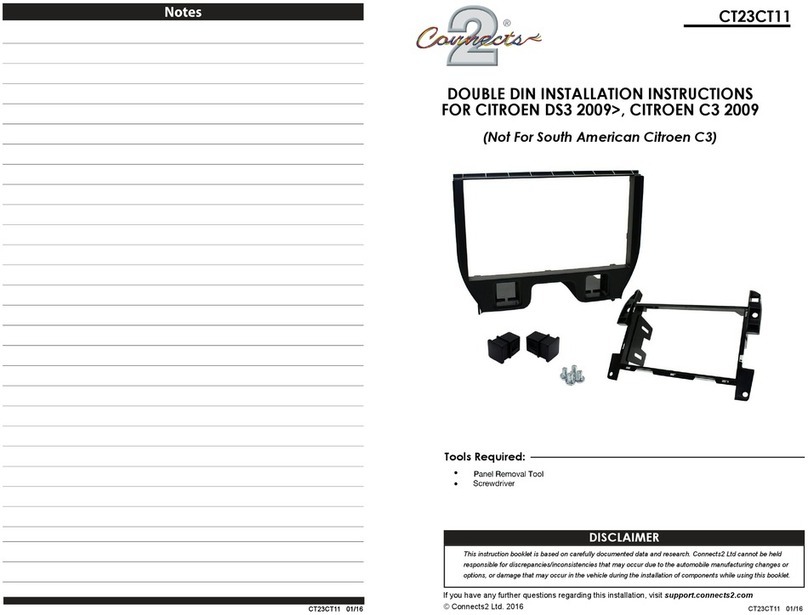
Connects2 CT23CT11 User manual

Connects2

Connects2 CT23CT11 User manual

Connects2 AdaptivMini ADVM-AU6 User manual

Connects2

Connects2 AdaptivMini ADVM-AU6 User manual

Connects2 CAN-Connect CANHBJP1 User manual

Connects2

Connects2 CAN-Connect CANHBJP1 User manual

Connects2 CAM-AR1-AD User manual

Connects2

Connects2 CAM-AR1-AD User manual

Connects2 43uft03 User manual

Connects2

Connects2 43uft03 User manual

Connects2 CAM-58 User manual

Connects2

Connects2 CAM-58 User manual

Connects2 CAM-KIT12 User manual

Connects2

Connects2 CAM-KIT12 User manual

Connects2 Aerpro CAKI01 User manual

Connects2

Connects2 Aerpro CAKI01 User manual

Connects2 CT23VW21 User manual

Connects2

Connects2 CT23VW21 User manual

Connects2 CAM-BM1-AD User manual

Connects2

Connects2 CAM-BM1-AD User manual

Connects2 CTULR04 User manual

Connects2

Connects2 CTULR04 User manual

Connects2 CT23MB25/L User manual

Connects2

Connects2 CT23MB25/L User manual

Connects2 CT23AU13/L User manual

Connects2

Connects2 CT23AU13/L User manual

Connects2 CTUSK03 User manual

Connects2

Connects2 CTUSK03 User manual

Connects2 CAM-63 User manual

Connects2

Connects2 CAM-63 User manual

Connects2 CT23CA06 User manual

Connects2

Connects2 CT23CA06 User manual

Connects2 CT23MB26L User manual

Connects2

Connects2 CT23MB26L User manual

Connects2 CAM-LR1-AD User manual

Connects2

Connects2 CAM-LR1-AD User manual

Connects2 CT23SK05 User manual

Connects2

Connects2 CT23SK05 User manual

Connects2 CTKMZ01 User manual

Connects2

Connects2 CTKMZ01 User manual

Connects2 CAM-MB13 User manual

Connects2

Connects2 CAM-MB13 User manual

Connects2 Gator G162V User manual

Connects2

Connects2 Gator G162V User manual

Popular Automobile Accessories manuals by other brands

Volvo TRAVEL ACTIVE 500 Accessories User Guide

Volvo

Volvo TRAVEL ACTIVE 500 Accessories User Guide

Romik 2137 2D installation instructions

Romik

Romik 2137 2D installation instructions

Rugged Ridge 13595.14 manual

Rugged Ridge

Rugged Ridge 13595.14 manual

Dakota Digital Retrotech RTX-64C-PU Instrument Installation

Dakota Digital

Dakota Digital Retrotech RTX-64C-PU Instrument Installation

Prorack K692 Fitting instructions

Prorack

Prorack K692 Fitting instructions

Waeco 8885100124 operating manual

Waeco

Waeco 8885100124 operating manual

ACV 391143-01-1 installation manual

ACV

ACV 391143-01-1 installation manual

Top Auto BRK600 user manual

Top Auto

Top Auto BRK600 user manual

Circontrol Wallbox eNext Series installation manual

Circontrol

Circontrol Wallbox eNext Series installation manual

Thule 1091 instructions

Thule

Thule 1091 instructions

Seizmik 76-10163 manual

Seizmik

Seizmik 76-10163 manual

Rola PMX124 Fitting instructions

Rola

Rola PMX124 Fitting instructions

Pyle PLCAPKT12 Quick and easy installation

Pyle

Pyle PLCAPKT12 Quick and easy installation

Rac Black Box Installation

Rac

Rac Black Box Installation

Dakota Digital VHX-66F-BRO manual

Dakota Digital

Dakota Digital VHX-66F-BRO manual

Airxcel Aqua-Hot GEN1 Series installation manual

Airxcel

Airxcel Aqua-Hot GEN1 Series installation manual

APA 16166 operating instructions

APA

APA 16166 operating instructions

Thule 129 Mounting & installation

Thule

Thule 129 Mounting & installation

manuals.online logo
manuals.online logoBrands
  • About & Mission
  • Contact us
  • Privacy Policy
  • Terms and Conditions

Copyright 2025 Manuals.Online. All Rights Reserved.