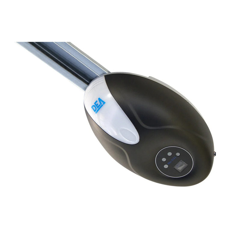
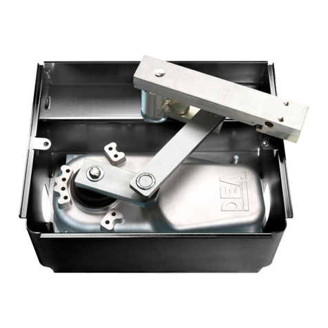
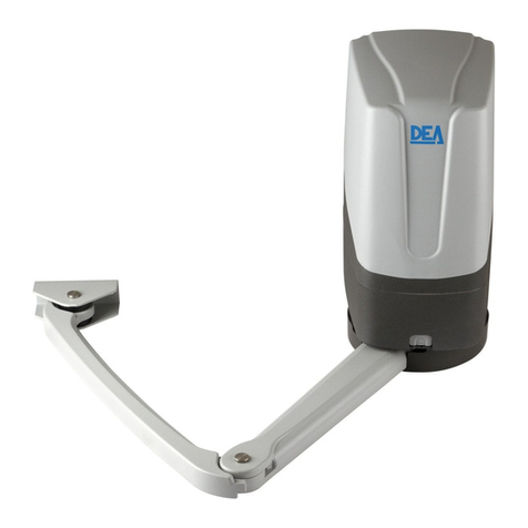
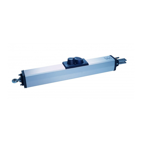
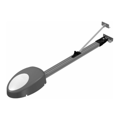
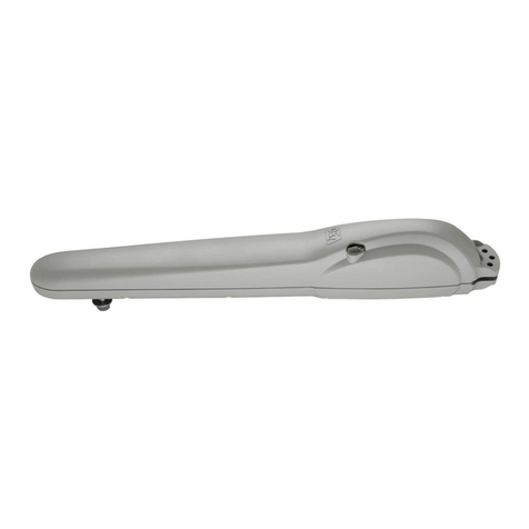
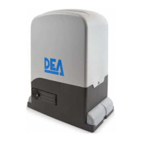
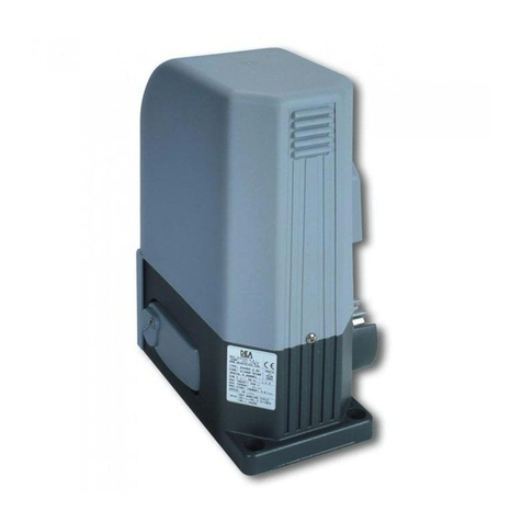
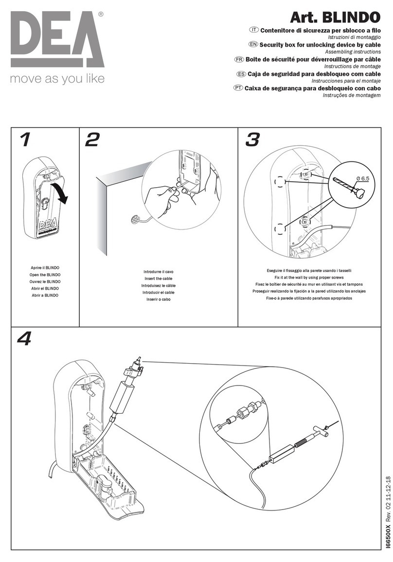
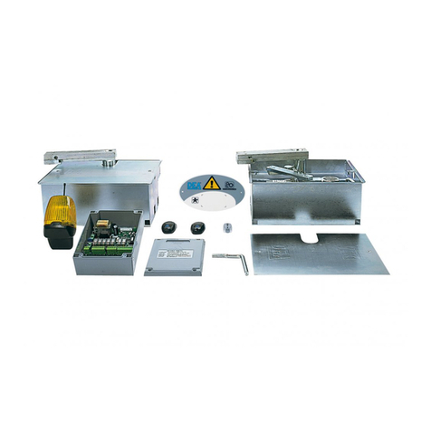
Dea Look Series Product manual

I6270XX Rev.07 22-10-09
LOOK
Operatore elettromeccanico per cancelli ad anta battente
Istruzioni d’uso ed avvertenze
Electro-mechanical operator for swing gates
Operating instructions and warnings
Opérateur électromécanique pour portails battants
Notice d’emploi et avertissements
Operador electromecánico para puertas con hoja batiente
Instrucciones de uso y advertencias
Operador electromecânico para portões de folha batente
Instruções para utilização e advertências
BATTENTE

Avvertimento
Warning
Avertissement
Advertencia
Advertência
Pericolo
Danger
Danger
Peligro
Perigo
Consultazione
Consultation
Consultation
Consultación
Consulta
Osservazione
Observation
Observation
Observación
Observação
Ispezione
Inspection
Inspection
Inspección
Inspecção
Certificazione
Certification
Certification
Certificación
Certificado
UTILIZZO DEL LIBRETTO
Per facilitare la comunicazione e la rintracciabilità di particolari
importanti informazioni all’interno del testo DEA System adotta la
simbologia riportata.
USE OF THIS BOOKLET
In order to facilitate communication and the traceability of parti-
cularly important parts of the text, DEA System adopts the symbols
provided.
UTILISATION DE CE LIVRET
Pour faciliter la communication et le repérage de renseignements
spéciaux et importants à l’intérieur du texte, DEA System a adopté
la symbologie indiquée.
UTILIZACIÓN DEL MANUAL
Para facilitar la comunicación y la trazabilidad de informaciones de
particular importancia, DEA System adopta, en el interior del texto,
la simbología reproducida.
UTILIZAÇÃO DO FOLHETO
Para facilitar a comunicação e localizar pormenores importantes de
informações no interior do texto, a DEA System adoptou os símbo-
los apresentados.

DICHIARAZIONE DI CONFORMITA’
DECLARATION OF CONFORMITY
DECLARATION DE CONFORMTÉ
DECLARACIÓN DE CONFORMIDAD
DECLARAÇÃO DE CONFORMIDADE
Il sottoscritto, rappresentante il seguente costruttore
The undersigned, representative of following manufacturer
Le soussigné, représentant le fabricant suivant
El abajo firmante, representante el fabricante siguiente
O abaixo-assinado, representando o seguinte construtor
DEA SYSTEM S.p.A.
Via Della Tecnica, 6
36013 PIOVENE ROCCHETTE (VI) - ITALY
dichiara che gli apparecchi denominati
hereby certifies that the equipment known as
déclare que les appareils nommés
declara que los equipos denominados
declara que os aparelhos denominados
350, 351, 351EN, 352, 353, 354, 355, 355EN, 356
357, 358, 371, 372, 373, 374
Operatori elettromeccanici per l’apertura di cancelli ad anta
Electro-mechanical ram for swing gates
Opérateurs électromécaniques pour portails à vantaux
Sistemas electromecánicos para aberturas de puertas batientes
Operador electro-mecânico para a apertura de portões de folha batente
sono conformi alle disposizioni legislative che traspongono le seguenti Direttive
conform to the laws and regulations that comply with the following Directives
sont conformes aux termes des lois qui respectent les Directives suivantes
son conformes con las disposiciones legislativas que incorporan las siguientes Directivas:
são em conformidade as disposições de lei que respeitan as Directivas seguint es
• Direttiva2006/42/CE(DirettivaMacchine)
• Direttiva2006/95/CE(DirettivaBassaTensione)
• Direttiva2004/108/CE(DirettivaEMC)
• Direttiva1999/5/CE(DirettivaRadio)
e che sono state applicate le norme e/o specifiche tecniche di seguito indicate
and that the following norms and/or technical specification have been applied
et que les normes et/ou prescriptions techniques suivantes ont étés appliquées
y que se han aplicado las normas y/o especificaciones técnicas indicadas a continuación:
e que foram aplicadas as normas e/ou especificações técnicas indicadas a seguir:
ENISO12100-1:2003;ENISO12100-2:2003;ENISO13857:2008;EN349:1993+A1:2008;EN12635:2002+
A1:2008;ENISO13849-1:2008;ENISO14121-1:2007
EN60335-1:2002+A11:2004+A1:2004+A12:2006+A2:2006.
EN 61000-6-2 :2005; EN 61000-6-3 :2007.
EN300220-2V2.1.2+;EN301489-01V1.8.1.
Il sottoscritto dichiara che i prodotti elencati sopra non possono essere messi in funzione prima che la mac-
china sulla quale sono installati sia stata marcata CE in conformità a tutte le Direttive applicabili.
The underwritten declares that the above-mentioned products cannot be put into service unless the machinery
they are installed on carry the EC Mark in conformity to all applicable Directives.
Le soussigné déclare que les produits énumérés ci-dessus ne peuvent pas être mis en service avant que la
machine sur la quelle ils sont installés soit marquée CE en conformité à toutes les Directives applicables.
El suscrito declara que los productos arriba mencionados pueden ponerse en funcionamiento exclusivamente
después de que la máquina en la que han sido instalados haya sido marcada CE en conformidad con todas
las Directivas de aplicación.
O abaixo-assinado declara que os produtos citados acima, não podem ser colocados em função antes que
a máquina na qual estão instalados foram marcada CE em conformidade a todas as Directivas aplicaveis.
PIOVENE ROCCHETTE (VI) ITALY, 04/02/09 LIEVORE TIZIANO
Amministratore

LOOK
Istruzioni d’uso ed avvertenze ad utilizzo
esclusivo di personale qualificato
2
SOMMARIO
Dichiarazione del fabbricante........................1
PREMESSA .......................................................2
1 CONFORMITÀ DEL PRODOTTO........................2
2 RIEPILOGO AVVERTENZE IN MERITO
AI RISCHI RESIDUI...........................................2
3 MODELLI E CONTENUTO DELL’IMBALLO.........2
4 ISTRUZIONI PER L’USO ...................................3
4.1 Descrizione del prodotto .......................3
4.2 Dati tecnici .............................................3
4.3 Riepilogo indicazioni per la marcatura 3
4.4 Condizioni di utilizzazione previste ......3
4.5 Istruzioni per eseguire senza rischio ....4
4.5.1 Installazione, montaggio
e smontaggio – 4
4.5.2 Messa in funzione e
regolazione – 4
4.5.3 Impiego ed utilizzazione – 5
4.5.4 Manutenzione e riparazione – 5
4.6 Addestramento......................................6
4.7 Controindicazioni di utilizzazione.........6
5 LISTA PARTI ORDINABILI.................................6
6 ASSIEME COMPLETO DELLA CHIUSURA ..........6
6.1 Livello minimo di protezione
del bordo principale..............................6
6.2 Impatto e schiacciamento
nell’area di apertura.............................6
6.3 Impatto nell’area di chiusura
o di apertura .........................................6
Esempio di installazione tipica............32
ALLEGATI
- Istruzioni per l’utente finale (inserto centrale
staccabile)
- Condizioni di Garanzia
PREMESSA
SCOPO DELLE ISTRUZIONI
Queste istruzioni sono state redatte dal costruttore e sono
parte integrante del prodotto. Le operazioni contenute sono
dirette a personale qualificato. Si raccomanda di leggerle
e conservarle per un riferimento futuro.
I capitoli “2 RIEPILOGO AVVERTENZE IN MERITO AI RISCHI
RESIDUI” e “4 ISTRUZIONI PER L’USO” contengono le infor-
mazioni che DEA System fornisce in modo tale che il prodotto
soddisfi sempre i Requisiti Essenziali di Sicurezza previsti dalla
Direttiva Macchine (Direttiva Europea 2006/42/CE).
Leggere attentamente questi capitoli in quanto for-
niscono importanti istruzioni per la sicurezza d’installazione,
d’uso e di manutenzione ed importanti avvertenze in merito ai
rischi residui che permangono malgrado siano adottate tutte le
disposizioni descritte.
Il prodotto è destinato ad essere incorporato in sistemi
completi di chiusura per i quali si applicano specifici riferimenti
legislativi. Il capitolo “6 ASSIEME COMPLETO DELLA CHIUSU-
RA” fornisce alcune indicazioni utili per il rispetto dei Requisiti
Essenziali di Sicurezza per particolari tipologie di chiusure.
1 CONFORMITÀ DEL PRODOTTO
LOOK è un prodotto marcato CE. DEA System as-
sicura la conformità del prodotto alle Direttive Europee
2006/42/CE sicurezza macchine, 2004/108/CE compa-
tibilità elettromagnetica e 2006/95/CE apparecchi elet-
trici a bassa tensione. DEA System allega alle presen-
ti istruzioni la Dichiarazione del Fabbricante (Cfr Direttiva
2006/42/CE Art. 4 comma 2).
2 RIEPILOGO AVVERTENZE
IN MERITO AI RISCHI RESIDUI
Leggere attentamente; la mancanza del rispetto delle se-
guenti avvertenze, può generare situazioni di pericolo.
ATTENZIONE L’utilizzo del prodotto in condizioni ano-
male non previste dal costruttore può generare situazioni di
pericolo; rispettare le condizioni previste dalle presenti istru-
zioni. A1
ATTENZIONE In nessun caso utilizzare il prodotto in
presenza di atmosfera eplosiva. In nessun caso utilizzare il
prodotto in ambienti che possono essere aggressivi e danneg-
giare parti del prodotto. A2
ATTENZIONE Altre operazioni di regolazione/taratura
diverse dalla regolazione dei finecorsa e dall’impostazione
dei parametri della centrale di comando sono eseguite dal
produttore. L’intervento su queste può causare malfunziona-
mento e/o situazioni di pericolo per persone, animali e cose.
Evitare ogni intervento non autorizzato da DEA System.A4
ATTENZIONE L’utilizzo di parti di ricambio non indicate
da DEA System e/o il riassemblaggio non corretto possono
causare situazioni di pericolo per persone, animali e cose;
possono inoltre causare malfunzionamenti al prodotto; uti-
lizzare sempre le parti indicate da DEA System e seguire le
istruzioni per l’assemblaggio. A5
ATTENZIONE La conoscenza del funzionamento dello
sblocco manuale (vedi F4 pag. 40) di LOOK è molto impor-
tante per tutti gli utenti dell’automatismo in quanto, in mo-
menti di emergenza, la mancanza di tempestività nell’agire su
tale dispositivo può causare situazioni di pericolo. L’allegato
staccabile delle presenti istruzioni ne illustra il funzionamento;
l’installatore è tenuto a consegnarla all’utente finale. A6
ATTENZIONE In ottemperanza alla Direttiva UE 2002/
96/EC sui rifiuti di apparecchiature elettriche ed elettroniche
(RAEE), questo prodotto elettrico non deve essere smaltito
come rifiuto municipale misto. Si prega di smaltire il prodotto
portandolo al punto di raccolta municipale locale per un op-
portuno riciclaggio.
3 MODELLI E CONTENUTO IMBALLO
Con la denominazione LOOK viene identificata una fami-
glia di operatori elettromeccanici con caratteristiche diverse per
quanto riguarda la dimensione dell’anta alla quale è idoneo, la
reversibilità e la tensione di alimentazione del motore.
Gli articoli DEA System che compongono la serie sono ri-
portati nella seguente tabella.
LOOK
Operatore elettromeccanico per cancelli ad anta battente
Istruzioni d’uso ed avvertenze ITALIANO

LOOK
Istruzioni d’uso ed avvertenze ad utilizzo
esclusivo di personale qualificato
3
Tabella “MODELLI DISPONIBILI”
Articolo
Corsa
stelo
(mm)
Anta
fino
a mt
Tensione
aliment.
motore
Rever-
sibile
Copri-
stelo
Fine-
corsa
Enco-
der
350 320 3 230 V ~ NO NO NO NO
351 320 3 230 V ~ NO SÌ NO NO
351EN 320 3 230 V ~ NO SI NO SI
352 320 3 230 V ~ NO SÌ SÌ NO
353 320 3 230 V ~ SÌ SÌ NO NO
354 320 3 230 V ~ SÌ SÌ SÌ NO
355 520 4,5 230 V ~ NO SÌ NO NO
355EN 520 4,5 230 V ~ NO SI NO SI
356 520 4,5 230 V ~ NO SÌ SÌ NO
357 520 4,5 230 V ~ SÌ SÌ NO NO
358 520 4,5 230 V ~ SÌ SÌ SÌ NO
371 320 3 24 V NO SÌ NO NO
372 320 3 24 V NO SÌ SÌ NO
373 520 4,5 24 V NO SÌ NO NO
374 520 4,5 24 V NO SÌ SÌ NO
ATTENZIONE: Se la lunghezza dell’anta è maggiore ai
2 mt o se si utilizzano modelli reversibili è necessario instal-
lare l’elettroserratura per il blocco del cancello in posizione
di chiusura.
LOOK è completato da una serie di accessori opzionali che
sono riportati nella seguente tabella.
Tabella “ACCESSORI PRODOTTO”
Articolo Descrizione
0/354
Attacco posteriore
regolabile
+
Attacco anteriore con
fissaggio a vite
x LOOK corsa 320mm
0/355
Attacco posteriore
regolabile
+
Attacco anteriore con
fissaggio a vite
x LOOK corsa 520mm
Ispeziona il “Contenuto dell’imballo” a pag. 38 confrontan-
dolo con il tuo prodotto, ti potrà essere utile durante l’assem-
blaggio.
4 ISTRUZIONI PER L’USO
Contenuto conforme a quanto prescritto dalla Direttiva
2006/42/CE Allegato I punto 1.7.4.
4.1. Descrizione del prodotto
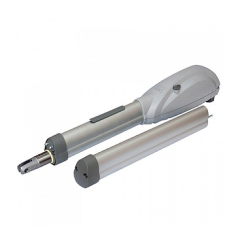
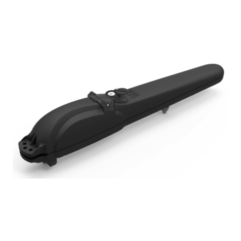
LOOK è un operatore elettromeccanico per l’automatismo
di cancelli ad anta. E’ costituito essenzialmente da un motori-
duttore meccanico che aziona, attraverso la vite di manovra, la
chiocciola fissata all’attacco anteriore (vedi F1 pag. 38-39).
4.2. Dati tecnici
Vedi tabella “DATI TECNICI”.
4.3. Riepilogo indicazioni per la marcatura
I dati riepilogativi per la marcatura CE sono riportati in parte
nell’etichetta applicata al prodotto (vedi posizione in F5 pag.
40); i dati del venditore sono riportati sulla Garanzia allegata (
inserto staccabile).
Al punto “4.2 Dati tecnici” sono evidenziate tutte le “carat-
teristiche indispensabili alla sicurezza d’esercizio”.
4.4. Condizioni di utilizzazione previste
LOOK è un prodotto destinato ad essere installato su cancelli
ad anta battente civili ed industriali come attuatore per l’automa-
tismo di funzionamento come illustrato in F3 pag. 39.
Verificare che la temperatura di utilizzo, il peso della porta, l’in-
tensità di lavoro ed il grado di protezione da polvere ed acqua
richiesti, rientrino nei limiti riportati in ”MODELLI DISPONIBILI”
e “4.2 Dati tecnici”.
La scelta dell’automatismo va fatta in funzione del cancello
da movimentare; l’attrito degli attacchi, il peso, la lunghezza/
altezza dell’anta, il grado di chiusura della superficie sono gli
elementi da considerare. Il grafico “LUNGHEZZA - PESO”, che
mette in relazione la lunghezza dell’anta con il suo peso, può es-
sere utilizzato per la scelta dell’automatismo in situazioni tipiche
(ATTENZIONE: L’installazione in zone soggette, per esempio, a
forte vento può ridurre notevolmente i dati riportati nel grafico).
ATTENZIONE L’utilizzo del prodotto in condizioni anoma-
le non previste dal costruttore può generare situazioni di peri-
colo; rispettare le condizioni previste dalle presenti istruzioni.
A1
Tabella “DATI TECNICI”
350
351
351EN
352
353
354
355
355EN
356
357
358
371
372
373
374
Tensione di alimentazione monofase 230 V ~ (50 Hz)
Tensione alimentazione motore (V) 230 V ~ 24 V
Potenza assorbita (W) 300 60
Condensatore incorporato (µF) 8 8 8 8 10 10 8 8 8 10 10 -
Ciclo di lavoro 16s-1s-16s x 6 VOLTE
30min PAUSA
3,5 min LAVORO
7min PAUSA
Forza di spinta (N) 1650 1650 1650 1650 1200 1200 1650 1650 1650 1200 1200 1000 1000 1000 1000
Corsa max (mm) 320 320 320 320 320 320 520 520 520 520 520 320 320 520 520
Velocità uscita stelo (cm/sec) 1,6 1,6 1,6 1,6 2,0 2,0 1,6 1,6 1,6 2,0 2,0 1,75
Peso del prodotto con imballo (kg) 9 9,5 9
Temperature limite di funzionamento (°C) -20 ÷ 40
Grado di protezione IP 24
Dimensioni di ingombro (mm) vedi F2 pag. 38-39

LOOK
Istruzioni d’uso ed avvertenze ad utilizzo
esclusivo di personale qualificato
4
4.5. Istruzioni per eseguire senza rischio
1 2 3 4
800
600
400
200
m
350, 351, 352, 371, 372
Kg
355, 356
373, 374
Grafico “LUNGHEZZA - PESO”
ATTENZIONE Per i modelli reversibili, a parità di lunghez-
za dell’anta, ridurre di 1/3 il peso ammissibile massimo della
porta rispetto a quanto indicato nel grafico “lunghezza-peso.
ATTENZIONE Se la lunghezza dell’anta è maggiore ai 2 mt
o se si utilizzano modelli reversibili è necessario installare l’elet-
troserratura per il blocco del cancello in posizione di chiusura.
4.5.1 Installazione, montaggio e smontaggio
Per una soddisfacente posa in opera del prodotto è impor-
tante:
• definireilprogettocompletodell’aperturaautomatica(fare
riferimento anche a “6 Assieme completo della chiusura); in
particolare, dopo aver valutato con attenzione le caratteri-
stiche dei supporti e del cancello designare tipo e posizione
degli attacchi in funzione anche dell’angolo di apertura che
si vuole ottenere (vedi F2, F3 pag. 38, 39).
• accertare che le condizioni meccaniche della porta siano
buone e tali da consentirne la motorizzazione in sicurezza.
Verificarne inoltre la corretta bilanciatura, ovvero che scorra
liberamente sui propri cardini e che una volta arrestata, in
una qualsiasi posizione della propria corsa, ne mantenga lo
stazionamento.
Il fissaggio degli attacchi va eseguito con particolare attenzione
sia sul pilastro che sul cancello ecco le misure consigliate da DEA
System (vedi F3 pag. 39). Fare particolare attenzione all’allinea-
mento orizzontale tra attacco posteriore ed attacco anteriore.
Considerazioni generiche per stabilire le misure di installazione:
• La somma delle quote A+B per aperture a 90° é pari alla
corsa dello stelo C.
•Peraumentarel’ampiezzadell’apertura:A+B<C.
•QuoteAeBinferioridaquelleconsigliatecomportanouna
velocità tangenziale dell’anta maggiore.
• Quote A e B discostate di oltre 5cm da quelle consigliate
comportano l’impossibilità della regolazione dei finecorsa
(dove previsti).
Per l’installazione dell’automatismo procedere come segue:
• Saldareoavvitarealpilastrol’attaccoposteriorenellaposi-
zione prefissata.
• MontareLOOKall’attaccoposterioreconl’appositoperno
• Eseguire l’operazione di sblocco manuale (vedi paragrafo
4.5.3) ed estrarre completamente lo stelo fino alla sua battuta.
• RibloccareLOOKefarrientrarelostelodicircamezzogiro.
• Fissarel’attaccoanterioreallostelodiLOOKconl’appositoperno.
• MantenendoLOOKinposizioneorizzontalesaldareoavvitare
alla porta l’attacco anteriore (con la porta totalmente chiusa).
• Eseguire l’operazione di sblocco e far compiere manual-
mente una manovra di completa apertura e chiusura per
verificare che il movimento sia libero e privo di attriti (con
eventuale copristelo montato).
(ATTENZIONE: è possibile che siano necessari dei fazzoletti di
rinforzo, da saldare agli attacchi, per conferire alla struttura una
sufficiente resistenza meccanica)
(ATTENZIONE: Ingrassare i perni prima del loro montaggio)
• Nelleversionicheprevedonoilcopristelodopolaregolazionedei
finecorsa procedere al suo montaggio come illustrato a pag. 34.
4.5.2 Messa in funzione e regolazione
ATTENZIONE Durante la fase di collegamento, vincolare
mediante fascette i conduttori in prossimità di morsetti e con-
nessioni elettriche, inoltre se possibile, sguainare adeguata-
mente i cavi per evitare conduttori troppo lunghi.
LOOK va collegato elettricamente ad una centrale di co-
mando DEA SYSTEM; fare riferimento alle istruzioni di tale
dispositivo per ulteriori informazioni.
Per il cablaggio elettrico di LOOK è necessario procedere come
segue (vedi anche pag. 33):
Versione 24V/230V standard
• Smontarelacoperturainplasticapostasullapartesottostan-
te di LOOK agendo sulle tre viti.
• Aprireunodeiquattrofori abbattibili posti sulla copertura
stessa, sciegliendo se si preferisce l’uscita del cavo verso il
basso o verso la parte posteriore.
• Introdurreneiforiappenapraticatiilpressacavoindotazio-
ne e fissarlo con la relativa ghiera.
• Utilizzareuncavo4x1mm²(permotori230V)o2x1,5mm²
(per motori 24V) flessibili da esterno (es. H05RN-F) e devo-
no provenire direttamente dalla centrale di comando senza
giunture e scatole di derivazione.
ATTENZIONE: Non sguainare eccessivamente i cavi di alimentazione.
• Eseguire il collegamento del motore come indicato nello
schema a pag.5.
Versione 24/230V con finecorsa
• Seguireleindicazionidellaversionestandardperilcollega-
mento dell’alimentazione del motore.
• Aprireunsecondoforoabbattibilenellacoperturainplastica
e applicare il secondo pressacavo (M16) in dotazione.
• Utilizzareuncavo3x0,75mm²(nonfornito)econsultarelo
schema a pag.5 per il corretto cablaggio dei finecorsa (trat-
teggio) alla centrale di comando.
Versione 230V con encoder
• Seguireleindicazionidellaversionestandardperilcollega-
mento dell’alimentazione del motore.
• Aprireunsecondoforoabbattibilenellacoperturainplastica
e applicare il secondo pressacavo (M16 ridotto) in dotazione.
• Utilizzareuncavo3x0,75mm²LiYY(nostroarticolo182021
non fornito) e consultare lo schema a pag.5 per il corretto
cablaggio dell’encoder alla centrale di comando.
• Utilizzareilcavettoconconnettorepanduitfornitonelkitpercol-
legare il cavo precedentemente utilizzato alla centrale di coman-
do, servendosi della morsettiera 3 poli fornita nella confezione.
ATTENZIONE: Nel caso di motori 230V collegare il conduttore di
terra all’apposito morsetto(vedi pag.33) avendo l’accortezza
di mantenerne la lunghezza superiore a quella dei condutto-
ri attivi in modo che in caso di fuoriuscita del cavo dalla sede
di fissaggio i conduttori attivi siano i primi a tendersi.
ATTENZIONE: Rispettare la polarità Fase-Neutro della tensione
di rete come indicato nei manuali d’uso delle centrali di co-
mando abbinabili a LOOK.
• Montarelacoperturainplastica,avendolacuranelrichiu-
derla, di accertare che i cavi elettrici non possano entrare in
contatto con parti in rotazione del motore.
LOOK
Istruzioni d’uso ed avvertenze ad utilizzo
esclusivo di personale qualificato
5
ATTENZIONE: I finecorsa del motore LOOK sono stati previsti esclu-
sivamente per il collegamento diretto ai rispettivi ingressi della
centrale di comando, e sono quindi sottoposti a bassissima ten-
sione di sicurezza. Mantenere quindi una adeguata distanza tra i
cavi finecorsa ed il cavo di alimentazione del motore a 230V.
ATTENZIONE: Duranete l’installazione mantenere i cavi di colle-
gamento ad una adeguata distanza dal motore, in modo che non
possano essere danneggiati durante il movimento dello stesso.
Collegamento per 230V standard e con finecorsa
CHIUDE
COMUNE
APRE
M
CENTRALE DI COMANDO
ELECTRONIC BOARD
ARMOIRE DE COMMANDE
CUADRO DE MANIOBRAS
CENTRAL DE COMANDO
FCC
FCA
N.C.
N.C.
FCA
COM
FCC
1(bianco)
2(blu)
3(nero)
4(marrone)
5(blu)
7(marrone)
6(blu)
Collegamento per 24V standard e con finecorsa
CHIUDE
APRE M
CENTRALE DI COMANDO
ELECTRONIC BOARD
ARMOIRE DE COMMANDE
CUADRO DE MANIOBRAS
CENTRAL DE COMANDO
FCC
FCA
N.C.
N.C.
FCA
COM
FCC
1(rosso)
2(blu)
4(marrone)
5(blu)
7(marrone)
6(blu)
Collegamento per 230V con encoder
Dopo l’installazione di LOOK è necessario eseguire la regola-
zione dei finecorsa (solo per i modelli che li prevedono) proce-
dendo come segue (vedi pag. 37):
•Allentare il dadi A in modo da poter agire sulle viti C e D.
•Regolare i finecorsa di chiusura e di apertura.
•Serrare i dadi A trattenendo le viti C e D con un cacciavite per
non alterare le regolazioni appena effettuate.
Per completare le regolazioni è necessario impostare i para-
metri della centrale di comando. Così facendo è possibile ese-
guire l’automatismo completo, con tutti i dispositivi necessari,
per il rispetto delle norme relative alla motorizzazione di porte
e cancelli. Fare riferimento al manuale d’uso della centrale di
comando impiegata.
É importante dopo l’installazione, verificare che tutte le
regolazioni siano state eseguite correttamente, e che i dispo-
sitivi di sicurezza e di sblocco svolgano adeguatamente la loro
funzione.
ATTENZIONE Altre operazioni di regolazione/taratura
diverse dalla regolazione dei finecorsa e dall’impostazione
dei parametri della centrale di comando sono eseguite dal
produttore. L’intervento su queste può causare malfunziona-
mento e/o situazioni di pericolo per persone, animali e cose.
Evitare ogni intervento non autorizzato da DEA System. A4
4.5.3 Impiego ed utilizzazione
Il prodotto è destinato ad essere parte di un assieme di ap-
parecchi che nel loro complesso realizzano l’automatismo del
cancello. DEA System presuppone che il suo utilizzo sia sempre
conforme a quanto prescritto dalle normative vigenti.
Tutti i modelli di LOOK sono dotati di un dispositivo di sbloc-
co; il cui funzionamento è:
•Toglierealimentazioneelettrica.
•RuotareilcoperchiettopostosuldorsodiLOOKinmodotale
da scoprire il foro sagomato sottostante.
•Inserirenelforosagomatolamanigliadisbloccoindotazione,
prestando attenzione al verso di inserimento (vedi F4 pag. 40).
•Ruotaredi90°lamanigliadisblocco.
•A questo punto LOOK è sbloccato e la porta, in assenza di altri
impedimenti è libera nei suoi movimenti.
•Il procedimento inverso riporta LOOK in condizioni di lavoro.
•Ricordarsi di riposizionare il coperchietto, affinchè il foro sa-
gomato sia sempre protetto da acqua e polvere (anche quando
l’automatismo deve rimanere “sbloccato” per lungo tempo.
ATTENZIONE Durante l’operazione di sblocco la porta
può presentare movimenti incontrollati: prestare la massima
attenzione al fine di evitare ogni possibile rischio.
4.5.4 Manutenzione e riparazione
Una buona manutenzione preventiva ed una regolare ispe-
zione al prodotto ne assicurano una lunga durata (vedi anche
“Garanzia”). In caso di guasto si può far riferimento alla tabella
“GUIDA RICERCA GUASTI” (vedi pagina 6) per cercare una
soluzione al problema; se i consigli riportati non portano alla
soluzione contattare DEA System.
Le operazioni di ispezione/manutenzione che sono da
programmare sul “registro di manutenzione dell’automazione
completa” sono:
TIPO DI INTERVENTO PERIODICITA’
pulizia superfici esterne 6 mesi
controllo serraggio viti 6 mesi
controllo funzionamento dello sblocco 6 mesi
ingrassaggio giunzioni 1 anno
ATTENZIONE Qualsiasi operazione d’installazione,
manutenzione, pulizia o riparazione dell’intero impianto de-
vono essere eseguite esclusivamente da personale qualificato;
operare sempre in mancanza di alimentazione e seguire scru-
polosamente tutte le norme vigenti nel paese in cui si effettua
l’installazione, in materia di impianti elettrici. A3
ATTENZIONE L’utilizzo di parti di ricambio non indicate
da DEA System e/o il riassemblaggio non corretto possono
causare situazioni di pericolo per persone, animali e cose;
possono inoltre causare malfunzionamenti al prodotto; uti-
lizzare sempre le parti indicate da DEA System e seguire le
istruzioni per l’assemblaggio. A5
4.6 Addestramento
Il funzionamento dell’automatismo completo, una volta
messo a punto dall’installatore, va attentamente illustrato
all’utente finale. E’ importante, per quanto riguarda LOOK,
istruire sul funzionamento dello sblocco (vedi “Allegati”) e su
quale sia il programma di manutenzione che lo riguarda (vedi
punto 4.5.5.).
ATTENZIONE La conoscenza del funzionamento dello
sblocco manuale (vedi F4 pag. 40) di LOOK è molto impor-
tante per tutti gli utenti dell’automatismo in quanto, in mo-
menti di emergenza, la mancanza di tempestività nell’agire su
tale dispositivo può causare situazioni di pericolo. L’allegato
staccabile delle presenti istruzioni ne illustra il funzionamento;
l’installatore è tenuto a consegnarla all’utente finale. A6
M
1(bianco)
2(blu)
3(nero)
ENCODER
}
white
green
brown
CHIUDE
COMUNE
APRE
w
h
i
t
e
b
r
o
w
n
green

LOOK
Istruzioni d’uso ed avvertenze ad utilizzo
esclusivo di personale qualificato
6
4.7 Controindicazioni di utilizzazione
Al capitolo “4.4 Condizioni di utilizzazione previste”sono
state descritte le condizioni per le quali il prodotto è stato pro-
gettato e testato. Non utilizzare il prodotto per scopi diversi.
ATTENZIONE L’utilizzo del prodotto in condizioni anoma-
le non previste dal costruttore può generare situazioni di peri-
colo; rispettare le condizioni previste dalle presenti istruzioni.
ATTENZIONE Per garantire il rispetto delle normative ed
un funzionamento in sicurezza del motoriduttore, si consiglia
di utilizzare esclusivamente centrali di comando Dea System.
5 LISTA PARTI ORDINABILI
La lista delle parti ordinabili (pag. 35) è un dettagliato elen-
co che accompagna l’esploso del prodotto e che deve essere
utilizzata per l’ordine di parti di ricambio.
In tale documento va sempre indicato fra l’altro:
• ilcodicedelprodotto(ricavabiledall’etichettaprodotto;vedi
F5 pag 40),
• ilnumerodiposizionedellapartenell’esploso,
• sedisponibile,puòessereutileladatadiacquistodelprodotto.
6 ASSIEME COMPLETO CHIUSURA
Questo capitolo, che illustra un’installazione tipo di un au-
tomatismo completo, viene redatto con lo scopo di informare
ed agevolare l’installatore nella scelta dei vari componenti nel
rispetto della Direttiva Macchine (2006/42/CE) e delle Normati-
ve Europee riguardanti la sicurezza (EN 12453 - EN 12445) per
l’installazione dei cancelli.
I dati riportati in questo capitolo non hanno lo scopo di essere
completi ed esaurienti. DEA System non può assumersi alcuna
responsabilità per eventuali errori, omissioni o approssimazioni.
6.1 Protezione del bordo principale
Tra i rischi più rilevanti che sono da considerare nell’auto-
mazione di un cancello ad anta battente vi è quello di schiac-
ciamento tra le due ante in chiusura, o tra di un’anta e la sua
battuta. Le norme citate prevedono che, per tale rischio, sia
adottata un’appropriata salvaguardia (ad es. limitazione delle
forze, rilevamento della presenza, distanze di sicurezza) anche
in considerazione della tipologia d’uso e di utenti a cui il cancel-
lo è destinato (vedi tabella “COMANDO DI ATTIVAZIONE”).
6.2 Schiacciamento nell’area di apertura
Possibile rischio di schiacciamento c’è nella zona che sta tra
il cancello in apertura e tipicamente un muro di recinzione od
altro ingombro. In F8 pag. 40 sono riportate le misure che è ne-
cessario rispettare nel caso non si ricorra alla limitazione delle
forze di impatto o a sistemi di rilevazione della presenza.
6.3 Impatto nell’area di chiusura o di apertura
Per evitare l’impatto di persone con l’anta nell’area di chiu-
sura installare una coppia di fotocellule (A) (altezza consigliata
500 mm) in modo tale da rilevare la presenza del parallelepi-
pedo di prova (B) (altezza 700 mm) posizionato come indicato
in F9 pag. 40.
N.B. Il campione per la rilevazione di presenza è un paral-
lelepipedo avente 3 facce con superficie chiara e riflettente e 3
facce con superficie scura e opaca.
Per ridurre ulteriormente la possibilità di impatto con l’anta
nell’area di apertura è possibile installare, in aggiunta, una cop-
pia di fotocellule (C) (altezza consigliata 500 mm) in modo tale
da rilevare la presenza del parallelepipedo di prova (D) (altezza
700 mm) posizionato come indicato in F9 pag. 40.
Tabella “GUIDA RICERCA GUASTI”
GUASTO CAUSA / RIMEDIO
Attivando il comando di apertura l’anta non
si muove ed il motore elettrico dell’operatore
non entra in funzione.
L’operatore non è correttamente alimentato; controllare i collegamenti, i
fusibili e le condizioni del cavo di alimentazione ed eventualmente prov-
vedere alla loro sostituzione/riparazione
Attivando il comando di apertura il motore
entra in funzione ma l’anta non si muove
Nel caso in cui l’operatore sia dotato di sblocco: controllare che sia chiuso
(vedi F4 pag. 40)
Controllare l’apparecchiatura elettronica di regolazione elettrica della
forza
Se a cancello chiuso il pistone si trova completamente a fine corsa rive-
dere il montaggio
Durante il movimento l’operatore funziona a
scatti
L’anta del cancello non ha un movimento libero; sbloccare il pistone e
sistemare i punti di rotazione
La potenza del motoriduttore potrebbe essere insufficiente rispetto alle
caratteristiche dell’anta del cancello; verificare la scelta del modello
Gli attacchi, anteriore e posteriore, dell’operatore flettono o sono fissati
in modo inadeguato; ripararli e/o rinforzarli

LOOK
Istruzioni d’uso ed avvertenze ad utilizzo
esclusivo di personale qualificato
7
1 5 6 7 8
2 3 4
10
9
L’INSTALLATORE DEVE
Si ricorda che chi vende e motorizza una porta/cancello diventa il costruttore della macchina porta/cancello automatico, e
deve predisporre e conservare il fascicolo tecnico che dovrà contenere i seguenti documenti (vedi allegato V della Direttiva
Macchine).
• Disegnocomplessivodellaporta/cancelloautomatico.
• Schemadeicollegamentielettriciedeicircuitidicomando.
• Analisideirischicomprendente:l’elencodeirequisitiessenzialiprevistinell’allegatoIdellaDirettivaMacchine;l’elencodei
rischi presentati dalla porta/cancello e la descrizione delle soluzioni adottate.
• Conservarequesteistruzionid’uso;conservareleistruzionid’usodeglialtricomponenti.
• Preparareleistruzioniperl’usoeleavvertenzegeneraliperlasicurezza(completandoquesteistruzionid’uso)econsegnarne
copia all’utilizzatore.
• Compilareilregistrodimanutenzioneeconsegnarnecopiaall’utilizzatore.
• RedigereladichiarazioneCEdiconformitàeconsegnarecopiaall’utilizzatore.
• Compilarel’etichettaolatargacompletadimarcaturaCEeapplicarlasullaporta/cancello.
N.B. Il fascicolo tecnico deve essere conservato e tenuto a disposizione delle autorità nazionali competenti per almeno dieci
anni a decorrere dalla data di costruzione della porta/cancello automatico.
Tabella “COMANDO DI ATTIVAZIONE”
Tipologia d’uso
Tipologia dei comandi di
attivazione Utenti informati
(area privata)
Utenti informati
(area pubblica) Utenti non informati
Comando a uomo
presente Controllo a pulsante Controllo a pulsante con
chiave Non è possibile il
comando a uomo presente
Comando ad impulso con
la porta in vista
Limitazione delle forze,
oppure
Rilevatori di presenza
Limitazione delle forze,
oppure
Rilevatori di presenza
Limitazione delle forze e
Fotocellule, oppure
Rilevatori di presenza
Comando ad impulso con
la porta non in vista
Limitazione delle forze,
oppure
Rilevatori di presenza
Limitazione delle forze e
Fotocellule, oppure
Rilevatori di presenza
Limitazione delle forze e
Fotocellule, oppure
Rilevatori di presenza
Comando automatico
(ad esempio, il comando di
chiusura temporizzata)
Limitazione delle forze e
Fotocellule, oppure
Rilevatori di presenza
Limitazione delle forze e
Fotocellule, oppure
Rilevatori di presenza
Limitazione delle forze e
Fotocellule, oppure
Rilevatori di presenza
ATTENZIONE Se sulla porta è installato un portoncino che può essere aperto quando la porta si muove, si deve adottare un
interruttore di finecorsa che garantisca la chiusura del portoncino durante il movimento della porta e che mantenga la funzione
protettiva anche in caso di guasto dell’interruttore stesso.
Pos. Descrizione
1 Selettore a chiave
102 Lux
2 Radiocomando
3 Colonnina Pilly 60
4 Bordo sensibile
5 Elettroserratura
6 Selettore digitale
FLIC/rad
7 Fotocellule serie
104 Lux
8 LOOK
9 Lampeggiante Lumy
10 Quadro di comando
Figura “ESEMPIO DI INSTALLAZIONE TIPICA”

LOOK
Operating instructions and warnings
only for qualified personnel
8
LOOK
Electro-mechanical ram for swing gates
Operating instructions and warnings ENGLISH
INDEX
Declaration by manifacturer ..........................1
OVERVIEW.......................................................8
1 PRODUCT CONFORMITY..................................8
2 RESIDUAL RISK WARNINGS ............................8
3 MODELS AND CONTENTS OF THE PACKAGE...8
4 OPERATING INSTRUCTIONS ...........................9
4.1 Product description................................9
4.2 Technical data........................................9
4.3 Labelling information............................9
4.4 Appropriate conditions of use ..............9
4.5 Instructions for risk-freeoperation ......10
4.5.1 Installation, assembly
and disassembly – 10
4.5.2 Starting and adjustment – 10
4.5.3 Use – 11
4.5.4 Maintenance and repair – 11
4.6 Training ...............................................11
4.7 Inappropriate use................................12
5 SPARE PARTS LIST..........................................12
6 COMPLETE CLOSING ASSEMBLY ...................12
6.1 Minimum level of protection
provided by the safety edge................12
6.2 Crushing in the opening area .............12
6.3 Impactintheopening/closingarea....12
Example of typical installation ............32
ANNEXES
- Instructions for the end user (central detacha-
ble file)
- Warranty terms
OVERVIEW
AIM OF THE INSTRUCTIONS
These instructions were prepared by the manufacturer and
are an integral part of the product. The operations described
are intended for adequately trained and qualified operators and
must be carefully read and conserved for future reference.
Chapters “2 RESIDUAL RISK WARNINGS” and “4 OPERA-
TING INSTRUCTIONS” contain all the information that DEA Sy-
stem provides in order for the product to constantly satisfy the
Essential Safety Requirements prescribed by the Machinery Di-
rective (European Directive 2006/42/CE).
Read these chapters carefully because they contain impor-
tant instructions for safe installation, use and maintenance and
important warnings regarding the residual risks remaining even
after all the safety devices and measures described have been
applied.
The product is designed for installation in complete closing
systems subject to specific legislation. Chapter 6 “COMPLE-
TE CLOSING ASSEMBLY” provides useful information for the
respect of the Essential Safety Requisites for special types of
closing.
1 PRODUCT CONFORMITY
The LOOK electromechanical operator bears the CE label.
DEA System guarantees the conformity of the product to Eu-
ropean Directives 2006/42/CE regarding machinery safety,
2004/108/CE electromagnetic compatibility and 2006/95/CE
low voltage electrical equipment. DEA System also encloses the
manufacturer’s Declaration of Conformity with these instructions
(see Directive 2006/42/CE Art. 4, paragraph 2).
2 RESIDUAL RISK WARNINGS
Read these warnings carefully; the failure to respect the fol-
lowing warnings can create risk situations.
WARNING The use of the product under unusual condi-
tions not foreseen by the manufacturer can create situations
of danger, and for this reason all the conditions prescribed in
these instructions must be respected. A1
WARNING Under no circumstances must the product be
used in explosive atmospheres or surroundings that may pro-
ve corrosive and damage parts of the product. A2
WARNING All the other adjustment/setting operations
beyond the adjustment of the oil flow are made by the manu-
facturer. Tampering with these settings may cause malfunction
and/or situations of risk to people, animals and property. Re-
frain from performing any operations not authorised by DEA
System. A4
WARNING The use of spare parts not indicated by DEA
System and/or incorrect re-assembly can create risk to people,
animals and property and also damage the product. For this
reason, always use only the parts indicated by DEA System
and scrupulously follow all assembly instructions. A5
WARNING Awareness of the operation of LOOK key-
release mechanism (see F4 Page 40) is essential for all users
of the automatism because the failure to use the device qui-
ckly during emergencies can jeopardise people, animals and
property. Enclosure to these instructions, which the installer is
required to deliver to the final user, illustrates operation and
can be detached. A6
WARNING In line with EU Directive 2002/96/EC for wa-
ste electrical and electronic equipment (WEEE), this electrical
product must not be disposed of as unsorted municipal waste.
Please dispose of this product by returning it to your local mu-
nicipal collection point for recycling.
3 MODELS AND CONTENTS
OF THE PACKAGE
The name LOOK identifies a series of electro-mechanical
gate operators with different features depending on size, locking
functions and motor power supply.
Articles included in the LOOK series are listed in the “AVAI-
LABLE MODELS” table.

LOOK
Operating instructions and warnings
only for qualified personnel
9
“AVAILABLE MODELS” table
Article
Stro-
ke
(mm)
Leaf
len-
gth
mt.
Motor
power
supply
Rever-
sible
Rod
cover
Limit
switch
Enco-
der
350 320 3 230 V ~ NO NO NO NO
351 320 3 230 V ~ NO YES NO NO
351EN 320 3 230 V ~ NO YES NO YES
352 320 3 230 V ~ NO YES YES NO
353 320 3 230 V ~ YES YES NO NO
354 320 3 230 V ~ YES YES YES NO
355 520 4,5 230 V ~ NO YES NO NO
355EN 520 4,5 230 V ~ NO YES NO YES
356 520 4,5 230 V ~ NO YES YES NO
357 520 4,5 230 V ~ YES YES NO NO
358 520 4,5 230 V ~ YES YES YES NO
371 320 3 24 V NO YES NO NO
372 320 3 24 V NO YES YES NO
373 520 4,5 24 V NO YES NO NO
374 520 4,5 24 V NO YES YES NO
WARNING: In case leaf length is more than 2 mt or in
case you use not self-locking models, an electro-lock must
be installed to hold the gate in closing position.
LOOK is completed by a set of accessories listed in the
“PRODUCT ACCESSORIES” table.
“PRODUCT ACCESSORIES” table
Article Description
0/354
Adjustable rear faste-
ning support
+
Front fastening support
x LOOK corsa 320mm
0/355
Adjustable rear faste-
ning support
+
Front fastening support
x LOOK corsa 520mm
Inspect the “Contents of the Package” on page 38 and com-
pare it with your product for useful consulting during assembly.
4 OPERATING INSTRUCTIONS
In compliance with Directive 2006/42/CE Enclosure I, Point
1.7.4.
4.1 Product description
LOOK is an electro-mechanical operator for swing gate au-
tomation. It is composed primarily of a mechanical gear motor
that drives the lead screw fastened to the front attachment by
means of the adjustment screw (see F1 Page 38-39).
4.2 Technical data
See the “TECHNICAL DATA” table.
4.3 Labelling information
Part of the summarised data for the CE label are listed in the
label applied to the product (see Position F5, Page 40); the data
regarding the seller are found in the enclosed Warranty, while
“Indispensable Operating Safety Elements” are found under
Point “4.2 Technical data”.
4.4 Appropriate conditions of use
LOOK is designed for installation in residential swing gates
as shown in F3 on Page 39.
Verify that operating temperature range, door weight, duty
cycle and water and powder protection degree required are the
ones listed in the “AVAILABLE MODELS” table and “4.2 TECH-
NICAL DATA”
The automation required must be selected according to the
gate to be moved; the friction on the attachments, the weight,
the length/height of the leaf and the degree of opening are the
elements to be considered.
The chart “LENGTH-WEIGHT” links the length of the leaf and
its weight in typical situations and helps the selection of the cor-
rect automation according to the gate to be automated.
(WARNING installation in windy areas or with poor structure
gates may remarkably reduce the data shown in the graphic).
WARNING The use of the product under unusual condi-
tions not foreseen by the manufacturer can create situations
of danger, and for this reason all the conditions prescribed in
these instructions must be respected. A1
TECHNICAL DATA” table
350
351
351EN
352
353
354
355
355EN
356
357
358
371
372
373
374
Single-phase power supply voltage 230 V ~ (50 Hz)
Motor power supply voltage (V) 230 V ~ 24 V
Absorbtion (W) 300 60
Built-in capacitor (µF) 8 8 8 8 10 10 8 8 8 10 10 -
Work cycle (%) 16s-1s-16s x 6 TIMES
30min PAUSE
3,5 min TIMES
7min PAUSE
Thrust force (N) 1650 1650 1650 1650 1200 1200 1650 1650 1650 1200 1200 1000 1000 1000 1000
Max. stroke (mm) 320 320 320 320 320 320 520 520 520 520 520 320 320 520 520
Rod exit speed (cm/sec) 1,6 1,6 1,6 1,6 2,0 2,0 1,6 1,6 1,6 2,0 2,0 1,75
Weight of product with packaging (kg) 9 9,5 9
Operating temperature range(°C) -20 ÷ 40
Degree of protection IP 24
Overall dimensions (mm) see F2 pag. 38-39

LOOK
Operating instructions and warnings
only for qualified personnel
10
4.5 Instructions for risk-free operation
WARNING With not self-locking models, with same leaf
length, reduce of 1/3 the door admissible weight compared to
what indicated in “Length-weight” chart.
WARNING In case the leaf is more than 2 m long or in
case you use not self-locking models, an electric-lock must be
installed to hold the gate in closing position.
4.5.1 Installation, assembly and disassembly
The following operations are essential to the correct laying
of the product:
• Thecarefuldefinitionoftheentireautomaticopeninglayout
(see also “6 Complete Closing Assembly”); in particular,
after carefully assessing the characteristics of the supports
and the gate, the attachments must also be designed and
positioned according to the angle of opening desired (see
F2, F3 Page 38-39).
• Verify that any mechanical feature of the gate are in good
conditions and allows a safe automation. Moreover check the
balancing, gate has to correctly and freely move on its hinges
and once stopped in any position, it has to stay blocked.
The fastening of the attachments must be performed with
extra care on both pillars and gate, here are the dimensions
suggested by DEA SYSTEM (see F3 page 39). Pay extra at-
tention to the horizontal alignment between rear fastening
support and front one.
General considerations to establish the installing dimen-
sions:
• ThesumofA+Bfor90°openingsisequaltoCrodrun
• A+B<Ctoincreasetheopeningangle
• AandBlowerthanwhatsuggested,involveahigherdoor
tangential speed
• If A and B are 5 cm greater than what suggested, limit
switches (if foreseen) adjustment won’t be possible
To install the operator proceed as follows:
• Weldorscrewtherearfasteningsupporttothepillar,inpre-
fixed position
• ApplyLOOKtotherearfasteningsupport
• Executethemanualunlockingoperation(seefollowingpara-
graph) and take off completely the rod
• LockLOOKagainandturntherodhalfway
• FixthefrontalfasteningsupporttoLOOKrod
• Weldorscrewthefrontalfasteningsupporttothedoor(with
door completely closed), by keeping LOOK in an horizontal
position
• Unlock again and make a complete opening and closing
cycle, this is to check that gate moves freely and without any
hindrance (with cover rod)
WARNING In order to make the structure sufficiently strong,
reinforcement plates to be fixed to attachments may be ne-
cessary
WARNING Grease pins before assembly
• Forversionsthatforeseethecoverrod,adjustlimitswitches
while assembling (see page 34)
4.5.2 Starting and adjustment
WARNING During the connection phase, fasten the
electric cables with appropriate clamps near the terminal
boards and, when possible, unsheathe the cables to avoid
they are too long.
LOOK must be electrically connected to a DEA SYSTEM con-
trol panel; refer to the instructions provided for such device for
further information.
For LOOK wiring, proceed as follows (se also page 33):
24V/230V standard version
• RemovetheplasticcoverpositionedunderLOOK
• Openoneoffourshapedholesandchoosewherethecable
exit has to be
• Introducethecableclampandfixitbyitsnut
• Insertthepowersupplycableintotheclamp(comingfrom
the control panel): A quadrupole cable suitable for external
applicationswitha4x1mm²section(or2x1,5mm²for24V
operators)(minimum H05RN-F type) coming directly from
the control panel (without any connection and shunt box)
and supplied by the installer;
WARNING: do not remove too much outer insulation on the
power supply cables.
• Executemotorconnectionsasindicated:
24/230V version with limit switches
• Fortheoperatorpowersupplyconnectionfollowtheinstruc-
tions of the basic version.
• Openasecondholeintheplasticcoverandapplythese-
cond provided cable clamp (a reduced M16).
• Usea3x0,75mm²cable(notsupplied)andlookatthedia-
gram at page 11 for a correct limit switches wiring to the
control panel.
230V version with encoder
• Fortheoperatorpowersupplyconnectionfollowtheinstruc-
tions of the basic version.
• Openasecondholeintheplasticcoverandapplythesecond
provided cable clamp (a reduced M16).
• Usea3x0,5mm²LiYY(DEAart.182021)to be ordered a
part) and follow the diagram on page 11 to correctly connect
the encoder to the control board.
• Usethecablewithpanduitconnectorsuppliedinthekittocon-
nect the previously used cable to the control board, by using the
clamp 3 “poli” inside the package.
WARNING: Maintain the ground conductor at a major length
respect the active conductors so that, if the cable exit from its
fixing housing, the active conductors tighten up as first.
WARNING: Respect the Phase-Neutral polarity of the tension as
explained by the instructions manual of the control panels
of LOOK.
• Re-assembletheplasticcoverensuringthatanycabledonot
touch moving parts of the operator
WARNING: LOOK limit switches have been exclusively foresaw
to directly connect their inputs to the control panel and so
they are submitted to a very safety low tension. Therefore
keep a proper distance between limit switches cables and
power supply cable of 230V operator.
WARNING: while installing, maintain a proper distance between
the power cable conductors and the operator
“LENGTH-WEIGHT” chart
1 2 3 4
800
600
400
200
m
350, 351, 352, 371, 372
Kg
355, 356
373, 374

LOOK
Operating instructions and warnings
only for qualified personnel
11
Connection for the basic 230V with limit switches
CHIUDE
COMUNE
APRE
M
CENTRALE DI COMANDO
ELECTRONIC BOARD
ARMOIRE DE COMMANDE
CUADRO DE MANIOBRAS
CENTRAL DE COMANDO
FCC
FCA
N.C.
N.C.
FCA
COM
FCC
1(bianco)
2(blu)
3(nero)
4(marrone)
5(blu)
7(marrone)
6(blu)
Connection for the basic 24V with limit switches
CHIUDE
APRE M
CENTRALE DI COMANDO
ELECTRONIC BOARD
ARMOIRE DE COMMANDE
CUADRO DE MANIOBRAS
CENTRAL DE COMANDO
FCC
FCA
N.C.
N.C.
FCA
COM
FCC
1(rosso)
2(blu)
4(marrone)
5(blu)
7(marrone)
6(blu)
Connection for 230V with encoder
After the installing, limit switches must be adjusted (only for
models that foresee them) as follows (see pag. 37):
• UnscrewtheAfixingnutssotooperateonCandDscrews
• Adjustopeningandclosinglimitswitches
• ScrewtheAfixingscrewsbykeepingCandDblockedbya
screwdriver so to maintain the adjustments
Program the control board to complete all adjustments. It
is now possible to supply a complete installation in compliance
with all standards required for gate automation. See the instruc-
tions provided with the control panel to be connected.
Finally, verify that all adjustments operations have been cor-
rectly performed and that safety devices and unlocking device
properly work.
WARNING All the other adjustment/setting operations
are made by the manufacturer. Tampering with these settings
may cause malfunction and/or situations of risk to people,
animals and property. Refrain from performing any opera-
tions not authorised by DEA System.
4.5.3 Use
The product is destined for incorporation in the assembly of
devices that comprise the gate automation. DEA System assu-
mes that it will always be used in compliance with the standards
and regulations in force.
All LOOK models are equipped with an unlocking device
with the following operation:
• Disconnectpowersupply
• Turntheblackplasticcoversotodiscovertheshapedhole
• Inserttheunlockinghandle(F4pag.40)
• Turnitat90°
• AtthispointLOOKisunlockedandifnootherobstructions
are present, the gate is free to move
• Theopposite procedure returns LOOK operator to normal
working conditions
• Remember to protect the lock with the respective cover so
that the operator is protected by water or powder (even when
it remains unlocked for a long time)
WARNING during this operation gate may perform uncon-
trolled movements: operate with extra care so to avoid any risk.
4.5.4 Maintenance and repair
Good preventive maintenance and regular inspection ensu-
re long working life (see also “Warranty”). Consult the “TROU-
BLESHOOTING” table (see page 12) whenever anomalies are
observed in order to find the solution to the problem and con-
tact DEA System directly whenever the solution required is not
provided.
The inspection/maintenance operations to be routinely sche-
duled in the “complete automatism maintenance register” are:
INTERVENTION TYPE PERIODICITY
cleaning of external surfaces 6 months
checking of screw tightening 6 months
checking of unlocking device
operation 6 months
greasing of articulated joint 1 year
WARNING All installation, maintenance, cleaning or re-
pair operations on any part of the system must be performed
exclusively by qualified personnel with the power supply di-
sconnected working in strict compliance with the electrical stan-
dards and regulations in force in the nation of installation.
WARNING The use of spare parts not indicated by DEA
System and/or incorrect re-assembly can create risk to people,
animals and property and also damage the product. For this
reason, always use only the parts indicated by DEA System
and scrupulously follow all assembly instructions.
4.6 Training
After installation and setting, the correct operation of the
complete automatism must be carefully illustrated to the final
user. LOOK gate operator requires careful instruction on the
unlocking device (see “Enclosures”) in particular and the respec-
tive maintenance schedule (see Point 4.5.4.).
WARNING Awareness of the operation of LOOK
unlocking device (see F4 Page 40) is essential for all users of
the automation because the failure to use the device quickly
during emergencies can jeopardise people, animals and pro-
perty. An enclosure to these instructions, which the installer is
required to deliver to the final user, illustrates operation and
can be detached.
4.7 Inappropriate use
Chapter “4.4 Appropriate conditions of use” describes the
conditions for which the product has been designed and tested.
The product must never be used for other purposes.
WARNING The use of the product under unusual condi-
tions not foreseen by the manufacturer can create situations
of danger, and for this reason all the conditions prescribed in
these instructions must be respected.
WARNING To ensure compliance with regulations and
safe operation of the motor, we recommend to use DEA Sy-
stem control panels only.
M
1(bianco)
2(blu)
3(nero)
ENCODER
}
white
green
brown
CHIUDE
COMUNE
APRE
w
h
i
t
e
b
r
o
w
n
green

LOOK
Operating instructions and warnings
only for qualified personnel
12
5 SPARE PARTS LIST
The list of spare parts that can be ordered (Page 35) is a
detailed list that accompanies the exploded view of the product
and must be used to order spare parts.
The following data must always be provided when ordering
spare parts:
• thecodeoftheproduct(seenontheproductlabel;seeF5,
Page 40)
• thepart’spositionnumberintheexplodedview
• ifavailable, the product’s purchase datemay be useful in
some cases
6 COMPLETE CLOSING ASSEMBLY
This chapter illustrates the typical installation of a comple-
te automatism for the purpose of informing and assisting the
installer in the selection of the various parts to be used in com-
pliance with Machinery Directive (2006/42/CE) and European
Safety Standards (EN 12453 - EN 12445) for gate installation.
The data provided in this chapter are neither complete nor
exhaustive, and DEA System declines all liability for any errors,
omissions or inaccuracies that may occur.
6.1 Minimum level of protection provided by the
safety edge
Among the most serious risks to be considered for the auto-
mation of a swing gate is the risk of crushing between two leafs or
between one leaf and its stop in closing position. Regulations pre-
scribe the adoption of a proper control against such risk (e.g. limit
of forces, presence detection, safety distances) depending on the
use foreseen for the gate (see the “OPERATING CONTROL” table)
6.2 Crushing in the opening area
The risk of crushing can also arise in the area between the
gate being opened and the wall or other construction behind
it. F8 on Page 40 provides the measurements that must be re-
spected whenever measures are not taken to limit the impact
force or whenever presence detection systems are not used.
6.3 Impact in the opening/closing area
In order to avoid crushing by the gate wing in the closing
area, install a pair of photocells (A) (recommended height: 500
mm) in order to detect the presence of the test parallelepiped (B)
(height: 700 mm) positioned as shown in F9 on Page 40.
Note. The presence detection test sample is a parallelepiped
with 3 sides with light-coloured reflecting surfaces and 3 sides
with dark-coloured, opaque surfaces.
In order to further reduce the risk of impact with the gate
wing in the opening area, an extra pair of photocells (C) (re-
commended height: 500 mm) can be installed for the detection
of the presence of the test parallelepiped (D) (height: 700 mm)
positioned as shown in F9 on Page 40.
“TROUBLE-SHOOTING” table
MALFUNCTION CAUSES / SOLUTIONS
When the opening command is given, the leaf fails
to move and the operator’s electric motor fails to
start
The operator is not receiving correct power supply. Check all connec-
tions, fuses, and the power supply cable conditions and replace or
repair if necessary
When the opening command is given, the motor
starts but the leaf fails to move
Whenever the operator is equipped with an unlocking device, make
sure that it is closed (see F4, Page 40)
Make sure that the electronic device for electric power adjustment is
in good condition
If the piston remains at the complete end of its stroke when the gate
is closed, review the assembly procedure
The operator jerks during movement
If the leaf does not move freely, release the ram and readjust the
rotation points
The power of the gear motor may be insufficient for the characteristi-
cs of the gate’s wing; check the choice of model whenever required
The operator’s front and rear attachments bend or are not fastened
correctly. Repair or replace

LOOK
Operating instructions and warnings
only for qualified personnel
13
1 5 6 7 8
2 3 4
10
9
RESPONSIBILITIES OF THE INSTALLER
Remember that anyone who sells and/or motorises doors/gates becomes the manufacturer of the automatic door/gate
machine and must therefore prepare and conserve a technical folder that contains the following documents (see Machinery
Directive Enclosure V):
• Assemblydrawingoftheautomaticdoor/gate;
• Electricalconnectionandcontrolcircuitwiringdiagram;
• Riskanalysisincluding:alistoftheessentialsafetyrequirementsprovidedinMachineryDirectiveEnclosureI;alistoftherisks
posed by the door/gate and the description of the solutions adopted.
• Keeptheseoperatinginstructionsinasafeplacetogetherwiththeinstructionsforalltheothercomponents;
• Preparetheseoperatinginstructionsandgeneralsafetywarnings(forthecompletionoftheseoperatinginstructions)and
deliver a copy to the final user;
• Filloutthemaintenanceregisteranddeliveracopytothefinaluser;
• DrafttheCEdeclarationofconformityanddeliveracopytothefinaluser;
• FilloutthecompleteCElabelorplateandapplyittothedoor/gate.
Note: The technical folder must be conserved for inspection by the competent national authorities for at least ten years from
the date construction of the automatic door/gate.
“OPERATING CONTROL” table
Type of use
Type of control Informed users
(private areas)
Informed users
(public areas) Uninformed users
Person-present control Pushbutton control Pushbutton control with key The person-present control is
not possible
Pulse control with the gate in
sight
Force limitation
or
presence detectors
Force limitation
or
presence detectors
Force limitation
and photocells
or presence detectors
Pulse control with the gate not
in sight
Force limitation
or
presence detectors
Force limitation
and photocells
or presence detectors
Force limitation
and photocells
or presence detectors
Automatic control
(i.e. control with
timed closing)
Force limitation
and photocells
or presence detectors
Force limitation
and photocells
or presence detectors
Force limitation
and photocells
or presence detectors
Pos. Description
1 102 Lux key selector
2 Remote-control
3 Pilly 60 column
4 Safety edge
5 Electric lock
6 FLIC/rad digital
selector
7 104 Lux series
photocells
8 LOOK
9 Lumy flashing light
10 Control box
“EXAMPLE OF TYPICAL INSTALLATION” picture
WARNING In case a little pedestrian door is installed on the gate and it may be opened while the gate moves, it is necessary
to adopt a limit switch to grant that door closing while the gate moves and to maintain this protective function also in case of failure
of this security limit switch.

LOOK
Instrucciones de uso y advertencias de utili-
zación exclusivas para personal cualificado
14
INDEX
Déclaration du fabricant ................................1
INTRODUCTION ...........................................14
1 CONFORMITÉ DU PRODUIT...........................14
2 RÉCAPITULATIF DES AVERTISSEMENTS CON-
CERNANT LESRISQUES RÉSIDUELS LATENTS .14
3 MODÈLES ET CONTENUDE L’EMBALLAGE......14
4 INSTRUCTIONS POUR L’UTILISATION ...........15
4.1 Description du produit.........................15
4.2 Données techniques ............................15
4.3 Récapitulatif des indications
concernant le label ce .........................15
4.4 Conditions d’utilisation prévues..........15
4.5 Instructions pour opérersans risques..16
4.5.1 Installation, montage
et démontage – 16
4.5.2 Mise en service et régulation – 16
4.5.3 Usage et utilisation – 17
4.5.4 Maintenance et réparation – 17
4.6 Formation ............................................18
4.7 Contre-indications d’utilisation ...........18
5 LISTE DES PIÈCES QUE VOUS
POUVEZ COMMANDER .................................18
6 ENSEMBLE COMPLET DE LA FERMETURE .......18
6.1 Niveau minimum de protection
du bord principal.................................18
6.2 Écrasement dans la zone d’ouverture.18
6.3 Impact dans la zone
de fermeture ou d’ouverture...............18
Exemple d’installation typique............32
ANNEXES
- Instructions pour l’utilisateur final (dossier
central détachable)
- Conditions de garantie
INTRODUCTION
FINALITÉ DES INSTRUCTIONS
Ces instructions ont été rédigées par le constructeur et elles
font partie intégrante du produit. Les opérations contenues
s’adressent à des opérateurs qui ont été correctement
formés et reconnus aptes. Nous vous conseillons vivement de
lire ces instructions et de les garder pour toute exigence future.
Les chapitres “2 AVERTISSEMENTS CONCERNANT LES RI-
SQUES RÉSIDUELS LATENTS”, et “4 INSTRUCTIONS POUR
L’UTILISATION” contiennent les renseignements que DEA Sy-
stem fournit pour que le produit soit toujours conforme aux exi-
gences essentielles de sécurité qui sont prévues dans la Directive
Machines (Directive Européenne 2006/42/CE).
Lisez ces chapitres attentivement , car ils fournissent des
instructions importantes concernant la sécurité de l’installation,
l’utilisation et la maintenance, ainsi que des avertissements im-
portants au sujet des risques résiduels latents qui persistent bien
que l’on ait adopté toutes les dispositions indiquées.
Ce produit est destiné à être incorporé dans des systèmes de
fermeture complets, pour lesquels on applique des références
législatives spécifiques. Le chapitre “6 ENSEMBLE COMPLET DE
LA FERMETURE” fournit certaines indications qui sont utiles pour
se conformer aux conditions requises et essentielles de sécurité
de certaines typologies de fermetures spéciales.
1 CONFORMITÉ DU PRODUIT
LOOK est un produit labellisé CE. La Société DEA System
assure la conformité de ce produit aux Directives Européennes
2006/42/CE (sécurité machines), 2004/108/CE (compatibilité
électromagnétique), 2006/95/CE (appareils électriques à basse
tension). DEA System joint la Déclaration du Fabricant aux présen-
tes instructions (cf. Directive 2006/42/CE Art. 4 alinéa 2).
2 RÉCAPITULATIF DES AVERTIS
SEMENTS CONCERNANT LES RI
SQUES RÉSIDUELS LATENTS
Vous devez les lire attentivement. L’inobservation des avertis-
sements suivants peut rendre certaines situations dangereuses.
ATTENTION L’utilisation du produit dans des conditions
anormales non prévues par le constructeur peut se révéler
potentiellement dangereuse. Par conséquent, respectez les
conditions prévues dans les présentes instructions.
ATTENTION Vous ne devez absolument pas utiliser ce
produit dans un milieu explosible, ni dans des milieux qui
peuvent être agressifs et qui peuvent détériorer ses pièces.
ATTENTION D’autres opérations de régulation/
étalonnage différentes de la régulation de la portée sont exé-
cutées par le producteur. Si vous y touchez, cela peut causer
un dysfonctionnement et/ou représenter un danger potentiel
pour les personnes, les animaux et les choses. Evitez toute
intervention non autorisée par DEA System.
ATTENTION L’utilisation de pièces de rechange non indi-
quées par DEA System et/ou un réassemblage incorrect peu-
vent être potentiellement dangereux pour les personnes, les
animaux et les choses. De plus, cela peut provoquer des dy-
sfonctionnements du produit. Par conséquent, utilisez toujours
les pièces indiquées par DEA System et suivez les instructions
données pour l’assemblage.
ATTENTION Il est très important que tous les utilisateurs
de l’automatisation connaissent le fonctionnement du dispo-
sitif de déverrouillage manuel (voir F4 page 40) de LOOK,
dans la mesure où en cas d’urgence, si vous n’intervenez
pas rapidement sur ce dispositif, cela peut rendre la situation
dangereuse. L’annexe des présentes instructions est une page
volante illustrent ce fonctionnement. L’installateur doit la re-
mettre à l’utilisateur final.
ATTENTION Conformément à la Directive 2002/96/EC
sur les déchets d’équipements électriques et électroniques
(DEEE), ce produit électrique ne doit en aucun cas être mis au
rebut sous forme de déchet municipal non trié. Veuillez vous
débarrasser de ce produit en le renvoyant au point de ramas-
sage local dans votre municipalité, à des fins de recyclage.
3 MODÈLES ET CONTENU DE L’EMBALLAGE
La dénomination LOOK indique une famille d’opérateurs
éléctro-mécaniques ayant des caractéristiques différentes en ce
qui concerne la dimension du vantail, la réversibilité et
la tension d’alimentation du moteur. La série comprend les
articles DEA System indiqués dans le tableau qui suive.
LOOK
Opérateur électromécanique pour portails battants
Notice d’emploi et avertissements FRANÇAIS

LOOK
Notices d’emploi et avertissements
réservées au personnel qualifié
15
Tableau “MODELES DISPONIBLES”
Article
Cour-
setige
(mm)
Van-
tail
mt.
Tension
d’aliment.
moteur
Réver-
sible
Pro-
tection
tige
Fin de
course
Enco-
der
350 320 3 230 V ~ NON NON NON NON
351 320 3 230 V ~ NON OUI NON NON
351EN 320 3 230 V ~ NON OUI NON OUI
352 320 3 230 V ~ NON OUI OUI NON
353 320 3 230 V ~ OUI OUI NON NON
354 320 3 230 V ~ OUI OUI OUI NON
355 520 4,5 230 V ~ NON OUI NON NON
355EN 520 4,5 230 V ~ NON OUI NON OUI
356 520 4,5 230 V ~ NON OUI OUI NON
357 520 4,5 230 V ~ OUI OUI NON NON
358 520 4,5 230 V ~ OUI OUI OUI NON
371 320 3 24 V NON OUI NON NON
372 320 3 24 V NON OUI OUI NON
373 520 4,5 24 V NON OUI NON NON
374 520 4,5 24 V NON OUI OUI NON
ATTENTION Si la longueur du vantail est plus de 2 mt.
ou si vous utilisez de modèles réversibles il est nécessaire
installer l’éléctro-serrure pour bloquer le portail en position
de fermeture.
LOOK est complété par une série d’accessoires optionnels
indiqués dans le tableau qui suive.
Tableau “ACCESSOIRES PRODUIT”
0/354
Fixation postérieur
réglable
+
Fixation antérieur avec
fixage à vis
x LOOK course tige
320mm
0/355
Fixation postérieur
réglable
+
Fixation antérieur avec
fixage à vis
x LOOK course tige
520mm
Vérifiez le “Contenu de l’emballage” à la page 30 et com-
parez-le avec votre produit, cela pourra vous être utile pendant
l’assemblage.
4 INSTRUCTIONS POUR L’UTILISATION
Contenu conforme à ce qui est prescrit dans la Directive
2006/42/CE, Annexe I, point 1.7.4.
4.1 Description du produit
LOOK est un opérateur électromécanique destiné à l’auto-
matisation de portails battants. Il comprend principalement un
moto-réducteur mécanique qui actionne le limaçon solidarisé
à la fixation avant, grâce à la vis de manoeuvre (voir F1 page
38-39).
4.2 Données techniques
Voir tableau “DONNEES TECHNIQUES”.
4.3 Récapitulatif des indications
concernant le label CE
Une partie des données récapitulatives concernant le label
CE est indiquée sur l’étiquette qui est appliquée sur le produit
(voir position sur F5 page 40). Les données du vendeur sont
indiquées sur la Garantie qui est jointe.
Au point “4.2 Données techniques” nous avons indiqué tou-
tes les “caractéristiques indispensables à la sécurité du service”.
4.4 Conditions d’utilisation prévues
LOOK est un produit destiné à être installé sur des portails
battants à usage résidentiel et industriel comme actionneur pour
l’automatisation de fonctionnement, ainsi qu’il est illustré sur F3
page 39.
Vérifiez que la température d’utilisation, le poids de la porte,
l’intensité du travail et le degré de protection contre la poussière
et l’eau demandés, respectent les limites indiqués en “ MODE-
LES DISPONIBLES “ et “ 4.2 Données techniques “.
Il faut évidemment choisir l’automatisation en fonction du
portail à manoeuvrer. Les éléments dont il faut tenir compte
sont le frottement des fixations, le poids, la longueur/hauteur
du battant, le degré de fermeture de la surface. Nous vous pré-
sentons un graphique “LONGUEUR - POIDS”, où l’on considère
la longueur du vantail en fonction de son poids dans les situa-
tions typiques (ATTENTION : l’installation en zones sujettes, par
exemple, à fort vent peut réduire considérablement les données
indiquées dans le graphique ).
ATTENTION L’utilisation du produit dans des conditions
anormales non prévues par le constructeur peut se révéler po-
tentiellement dangereuse. Par conséquent, respectez les
conditions prévues dans les présentes instructions.
Tableau “DONNEES TECHNIQUES
350
351
351EN
352
353
354
355
355EN
356
357
358
371
372
373
374
Tension d’alimentation monophasée 230 V ~ (50 Hz)
Tension d’alimentation moteur (V) 230 V ~ 24 V
Puissance absorbée (W) 300 60
Condensateur incorporé (µF) 8 8 8 8 10 10 8 8 8 10 10 -
Cycle de travail (%) 16s-1s-16s x 6 TIMES
30min PAUSE
3,5 min TIMES
7min PAUSE
Force de poussée (N) 1650 1650 1650 1650 1200 1200 1650 1650 1650 1200 1200 1000 1000 1000 1000
Course max. (mm) 320 320 320 320 320 320 520 520 520 520 520 320 320 520 520
Entraxe max. fixations (mm) 1,6 1,6 1,6 1,6 2,0 2,0 1,6 1,6 1,6 2,0 2,0 1,75
Poids du produit (kg) 9 9,5 9
Température ambiante limite d’exploitation (°C) -20 ÷ 40
Degré de protection IP 24
Cotes d’encombrement (mm) Voir F2 pag. 38-39

LOOK
Notices d’emploi et avertissements
réservées au personnel qualifié
16
4.5 Instructions pour opérer sans risques
ATTENTIONPour les modèles réversibles, avec des battan-
ts de longueur identique, réduire de 1/3 le poids admissible
maximum de la porte par rapport à ce qui est indiqué dans le
graphique “ longueur-poids “.
ATTENTION Si la longueur du battant est plus de 2 mt., ou si
vous utilisez un des modèles réversibles, il faut installer une élé-
ctro-serrure pour bloquer le portail en position de fermeture.
4.5.1 Installation, montage et démontage
Pour une mise en oeuvre satisfaisante du produit il est im-
portant:
• dedéfinirleprojetcompletdel’ouvertureautomatique(con-
sultez également le paragraphe “6 Ensemble complet de la
fermeture). Une fois que vous avez attentivement évalué les
caractéristiques des supports et du portail, établissez notam-
ment le type et la position des fixations, et cela également en
fonction de l’angle d’ouverture que vous voulez obtenir (voir
F2 et F3 page 38-39).
• de vérifier que les conditions mécaniques du portail soient
bonnes et tels de consentir la motorisation en toute sûreté.
Il faut en plus vérifier que l’équilibrage soit correct, ou bien
que la porte coulisse librement sur ses gonds et que, un fois
arrêtée, dans n’importe quelle position de sa course, elle en
maintient le stationnement.
La fixation des attaches doit être exécuté avec attention soit sur
le pilier soit sur le portail, voici les dimensions suggérées par DEA
System (voir F3 page 39). Faites particulière attention à l’aligne-
ment horizontale pour les attaches postérieur et antérieur.
Considérations génériques pour établir les mesures de l’installation:
• LasommedesmesuresA+Bpourouverturesà90°estpaire
à la course de la tige C.
• Pouraugmenterl’étenduedel’ouverture:A+B<C
• SilesmesuresAetBontinférieursàcellessuggérées,elles
comportent une vitesse tangentiel majeur du vantail.
• SilesmesuresAetBsontplusde5cmquecellessuggérées,
elle comportent l’impossibilité de régler les fins de course (où
prévues)
Pour l’installation de l’automatisation, procéder comme il suit :
• souderouvisseraupilierl’attachepostérieurdanslaposi-
tion préfixée
• assemblerLOOKàl’attachepostérieuravecsonpivot
• exécuterl’opérationdedéverrouillagemanuel(voirparagraphe
qui suive) et extraire complètement la tige jusqu’à sa butée
• verrouillerdenouveauLOOKetfairerentrerlatiged’envi-
ron demi tour
• fixerl’attacheantérieuràlatigedeLOOKavecsonpivot
• en maintenant LOOK en position horizontale souder ou visser
l’attache antérieur à la porte (avec la porte complètement fermée)
• exécuter l’opération de déverrouillage et faire accomplir
manuellement une manœuvre complète d’ouverture et
fermeture pour vérifier que le mouvement soit libre et sans
frottements (avec éventuellement un couvre-tige monté)
(ATTENTION il est possible que des goussets de renfort soient
nécessaires, une fois soudés aux attaches ils donnent à la
structure une résistance mécanique plus forte)
(ATTENTION graisser les pivots avant leurs montage)
• pourlesversionsquiprévoientlecouvre-tige,aprèslarégulationdes
fins de course procéder au montage comme illustré à page 34.
4.5.2 Mise en service et régulation
ATTENTION Pendant la phase de connexion, gardez toujours
nettement séparés les câbles électriques en les fixant à l’aide de
pattes d’attache appropriés à proximité des borniers, et puis, si
possible est, dégainer les câbles afin qu’ils ne soient trop long.
LOOK doit être connecté électriquement à une armoire de
commande DEA SYSTEM ; référez vous aux instructions de ce
dispositif pour tout complément d’information.
Pour le câblage électrique de LOOK il faut procéder comme
il suit (voir page 33):
Version 24V/230V standard
•démonterlecapotenplastiquepositionnéesousleLOOKen
dévissant les trois vis
•ouvrirundesquatretrouspositionnéssurlecapot,enchoi-
sissant s’il faut faire sortir le câble vers le bas ou vers la
partie postérieur
•introduiredanscetroulepressecâbleendotationetlefixer
avec sa frette
•introduiredanslepressecâble,lecâbled’alimentation(qui
provient de l’armoire de commande): câble quadripolaire
pour applications flexibles d’externe avec section 4x1mm²
(2x1,5mm²pourmoteursen24V)(minimumtypeH05RN-F),
qui provient directement de l’armoire de commande (donc
sans joints et sans boîte de dérivation), fourni par l’installa-
teur
ATTENTION: Ne pas trop dénuder les câbles d’alimentation.
•exécuterlebranchementdumoteurcommeindiqué:
Version 24/230V avec fins de course
• Suivezlesindicationsdelaversionstandardpourlebran-
chement de l’alimentation moteur.
• Faitesundeuxièmetroudanslecapotetappliquezledeu-
xième collier pour câbles (M16) fourni.
• Utilisez un câble 3x0,75 mm² (non fourni) et regardez le
schéma de la page 17 pour brancher correctement les fins
de course à la platine de commande.
Version 230V avec encodeur
• Suivezlesindicationsdelaversionstandardpourlebran-
chement de l’alimentation moteur.
• Faitesundeuxièmetroudanslecapotetappliquezledeuxiè-
me collier pour câbles (M16 réduit) fourni.
• Utiliseruncâble3x0,75mm²LiYY(articleDEA182021non
fourni) et regardez le schéma de la page 17 pour brancher
correctement l’encodeur à la platine de commande.
• Utiliserunpetitcâbleavecconnecteur“panduit”fournidansle
kit pour connecter le câble utilisé précédemment à la platine de
commande, en utilisant le serre câble 3 “poli” fourni avec.
ATTENTION: tenez le conducteur de terre à une longueur
supérieur des conducteurs actifs afin que, en cas de sortie
du câble de son siège de fixage, les conducteurs actifs soient
les premiers qui se tendent.
ATTENTION: Respecter la polarité Phase-Neutre de la tension
du réseau comme indiqué par le manuel d’instructions des
platines de commande à installer avec le LOOK.
•Monterlecapotenplastique,faisantattentionquependant
la fermeture les câbles électriques ne touchent pas les parties
en rotation du moteur
ATTENTION: les fins de course du moteur LOOK ont été prévus
Graphique “LONGUEUR – POIDS”
1 2 3 4
800
600
400
200
m
350, 351, 352, 371, 372
Kg
355, 356
373, 374

LOOK
Notices d’emploi et avertissements
réservées au personnel qualifié
17
exclusivement pour le branchement direct aux respectives
entrées de la platine électronique et ils sont donc soumis
à une très basse tension de sécurité. Maintenir donc une
distance adéquate entre les câbles des fins de course et le
câble d’alimentation du moteur en 230V.
ATTENTION: Pendant l’installation, maintenir une distance propre
entre les conducteurs du câble d’alimentation et le moteur.
Branchement pour 230V standard et avec fins de course
CHIUDE
COMUNE
APRE
M
CENTRALE DI COMANDO
ELECTRONIC BOARD
ARMOIRE DE COMMANDE
CUADRO DE MANIOBRAS
CENTRAL DE COMANDO
FCC
FCA
N.C.
N.C.
FCA
COM
FCC
1(bianco)
2(blu)
3(nero)
4(marrone)
5(blu)
7(marrone)
6(blu)
Branchement pour 24V standard et avec fins de course
CHIUDE
APRE M
CENTRALE DI COMANDO
ELECTRONIC BOARD
ARMOIRE DE COMMANDE
CUADRO DE MANIOBRAS
CENTRAL DE COMANDO
FCC
FCA
N.C.
N.C.
FCA
COM
FCC
1(rosso)
2(blu)
4(marrone)
5(blu)
7(marrone)
6(blu)
Branchement pour 230V avec encodeur
Quand vous installez LOOK, vous devez régler la position des
fins de course (seulement pour les modèles qui les prévoient).
Pour effectuer cette régulation, procéder comme il suit (voir
page 37):
•dévissezlesécrousAdefaçondepouvoiragirsurlesvisCetD
•Réglezlesfinsdecoursedefermetureetouverture.
•VisserlesécrousAentenantlesvisCetDavecuntournevis
pour ne pas changer les réglages effectuées.
Au fin de compléter les réglages il est nécessaire établir les pa-
ramètres de l’armoire de commande. De cette façon il est possible
d’exécuter l’automation complète, avec tout les dispositifs nécessai-
res, pour le respect des normes pour la motorisation de portes et
portails. Référez vous au manuel d’instruction de l’armoire utilisée.
Il est important, après l’installation, de vérifier que tout les ré-
glages aient étés exécutées correctement et que les dispositifs de sé-
curité et de déverrouillage exercent convenablement leur fonction.
ATTENTION D’autres opérations de régulation/
étalonnage différentes des fins de course et de l’établissement
des paramètres sont exécutées par le producteur. Si vous y tou-
chez, cela peut causer un dysfonctionnement et/ou représenter
un danger potentiel pour les personnes, les animaux et les cho-
ses. Evitez toute intervention non autorisée par DEA System.
4.5.3 Usage et utilisation
Ce produit est destiné à être inséré dans un ensemble
d’appareils qui réalisent dans leur ensemble l’automatisation
du portail. DEA System part du principe que l’utilisation de ce
produit est toujours conforme à ce qui prescrit dans la régle-
mentation en vigueur.
Tous les modèles de LOOK sont équipés d’un dispositif de
déverrouillage qui fonctionne de la manière suivante:
•couperl’alimentation
•tournerlepetitcouverclepositionnésurLOOKdefaçonde
découvrir le trou façonné
•insérerencetroulapoignéededéverrouillageendotation,
faire attention au sens d’insertion (voir F2 page 40).
•tournerde90° (dans le sens des aiguilles d’une montreet
l’inverse) la poignée de déverrouillage
• à ce point LOOK est alors déverrouillé, et le portail, sans
autres entraves, est libre de manœuvrer
•LeprocédéinverseramèneLOOKdanssesconditionsdetravail.
•Rappelezvousdere-positionnerlecouvercleaufinqueletrou
soit toujours protégé de l’eau et de la poussière (même quand
l’automatisme doit rester “ déverrouillé “ pour long temps).
ATTENTION pendant l’opération de déverrouillage le
portail peut présenter de mouvements incontrôlés: faites
toujours attention afin d’éviter tout risques.
4.5.4 Maintenance et réparation
Une bonne maintenance préventive et une inspection ré-
gulière du produit assurent sa longue durée (voir également
“Garantie”). En cas de panne, vous pouvez consulter le tableau
de “GUIDE DE RECHERCHE DES PANNES” (voir page 18), pour
chercher une solution au problème. Si les conseils indiqués
n’apportent aucune solution, contactez DEA System.
Les opérations d’inspection/de maintenance qu’il faut pro-
grammer dans le “cahier de maintenance de l’automatisation
complète” sont les suivantes:
TYPE D’INTERVENTION PÉRIODICITÉ
nettoyage surfaces externes 6 mois
vérification serrage vis 6 mois
vérification fonctionnement du
dispositif de déverrouillage 6 mois
graissage joint à rotule 1 an
ATTENTION Toute opération d’installation, de mainte-
nance, de nettoyage ou de réparation de toute l’installation
doit être exécutée exclusivement par du personnel qualifié.
Opérez toujours quand l’alimentation est coupée, et con-
formez-vous rigoureusement à toutes les normes en matière
d’installations électriques en vigueur dans le pays où cette
automatisation doit être installée.
ATTENTION L’utilisation de pièces de rechange non indi-
quées par DEA System et/ou un réassemblage incorrect peu-
vent être potentiellement dangereux pour les personnes, les
animaux et les choses. De plus, cela peut provoquer des dy-
sfonctionnements du produit. Par conséquent, utilisez toujours
les pièces indiquées par DEA System et suivez les instructions
données pour l’assemblage.
4.6 Formation
Bien expliquer le fonctionnement de l’automatisme complète
une fois installé par l’installateur. Il est important, pour ce qui
concerne LOOK, avoir une bonne connaissance du fonctionne-
ment du déverrouillage (voir “ Annexes) et du programme de
maintenance qui le concerne (voir point 4.5.6).
M
1(bianco)
2(blu)
3(nero)
ENCODER
}
white
green
brown
CHIUDE
COMUNE
APRE
w
h
i
t
e
b
r
o
w
n
green

LOOK
Notices d’emploi et avertissements
réservées au personnel qualifié
18
ATTENTION Il est très important que tous les utilisateurs
de l’automatisation connaissent le fonctionnement du dispo-
sitif de déverrouillage manuel (voir F4 page 40) de LOOK,
dans la mesure où en cas d’urgence, si vous n’intervenez
pas rapidement sur ce dispositif, cela peut rendre la situation
dangereuse. L’annexe des présentes instructions est une page
volante qui illustre ce fonctionnement. L’installateur doit la
remettre à l’utilisateur final.
4.7 Contre-indications d’utilisation
Au chapitre “4.4 Conditions d’utilisation prévues” nous
avons décrit les conditions d’usage pour lesquelles le produit
a été conçu et testé. N’utilisez pas ce produit pour des usages
différents.
ATTENTION L’utilisation du produit dans des conditions
anormales non prévues par le constructeur peut se révéler
potentiellement dangereuse. Par conséquent, respectez les
conditions prévues dans les présentes instructions.
ATTENTION Afin de garantir le respect aux Normes et le
fonctionnement en complète sûreté du moteur, utilisez exclusi-
vement les platines de commande DEA System.
5 LISTE DES PIÈCES QUE VOUS
POUVEZ COMMANDER
La liste détaillée des pièces que vous pouvez commander
(page 35) accompagne le schéma éclaté du produit et vous de-
vez l’utiliser pour commander des pièces de rechange. Dans ce
document, vous devez toujours indiquer, entre autres:
•lecodeduproduit(quevoustrouvezsursonétiquette;voirF5
page 40);
•lenumérodelapositiondelapiècedansleschémaéclaté;
• la date d’achat du produit, si vous la connaissez (elle peut
être utile).
6 ENSEMBLE COMPLET
DE LA FERMETURE
Ce chapitre qui illustre l’installation type d’une automatisa-
tion complète a été rédigé dans le but d’informer et de faciliter
les choses à l’installateur au niveau du choix des différents com-
posants, conformément à la Directive Machines (2006/42/CE)
et aux Réglementations Européennes qui concernent la sécurité
(EN 12453 - EN 12445) d’installation des portails.
Les données indiquées dans ce chapitre n’ont pas la préten-
tion d’être complètes et exhaustives. DEA System décline toute
responsabilité en cas d’erreurs, d’omissions ou d’approxima-
tions.
6.1 Protection du bord principal
Parmi les risques les plus importants, et dont il faut tenir
compte dans l’automatisation d’un portail battant, il y a le risque
d’écrasement entre les deux battants à la fermeture, ou entre
un battant et sa butée. Les normes citées prévoient qu’en ce qui
concerne ce risque, il faut adopter l’une des typologies suivantes
d’activation, suivant le type d’utilisation auquel le portail est de-
stiné (voir tableau COMMANDE D’ACTIVATION).
6.2 Écrasement dans la zone d’ouverture
Il existe un risque d’écrasement, notamment dans la zone
qui se trouve entre le portail qui s’ouvre, et le mur de clôture, ou
autre obstacle. Sur F8 page 40, nous avons indiqué les mesures
qu’il faut respecter si l’on ne fait pas appel à la limitation des
forces d’impact ou à des systèmes de détection de la présence.
6.3 Impact dans la zone de fermeture ou d’ouvertu-
re
Pour éviter que les personnes n’aillent heurter le battant dans
la zone de fermeture, installez deux photocellules (A) (hauteur
conseillée 500 mm) de manière à détecter la présence du pa-
rallélépipède d’essai (B) (hauteur 700 mm), positionné comme
indiqué sur F9 page 40
N.B. le parallélépipède d’essai a 3 faces avec une surface
claire et réfléchissante, tandis que les trois autres ont une surface
sombre et opaque.
Pour réduire encore la possibilité d’impact contre le battant
dans la zone d’ouverture, vous pouvez installer deux photocel-
lules (C) (hauteur conseillée 500 mm) en plus, de manière à
détecter la présence du parallélépipède d’essai (D) (hauteur 700
mm), positionné comme indiqué sur F9 page 40.
Tableau de “RECHERCHE DES PANNES”
PANNE CAUSE/REMÈDE
Quand vous activez la commande d’ouvertu-
re, le battant ne se déplace pas et le moteur
électrique de l’opérateur ne démarre pas.
L’opérateur n’est pas alimenté correctement. Vérifiez les connexions, les
fusibles, l’état du câble d’alimentation et si besoin est, remplacez-les/
réparez-les.
Quand vous activez la commande d’ouverture,
le moteur entre en service mais le battant ne se
déplace pas.
Si l’opérateur est équipé d’un dispositif de déverrouillage, assurez-vous
qu’il est fermé (voir F4 page 40).
Vérifiez l’automation électronique qui régule la force électriquement.
Si le piston est complètement en fin de course quand le portail est
fermé,revoyez le montage.
Au cours de la manoeuvre, l’opérateur fonc-
tionne par saccades.
Le battant du portail n’a pas de mouvement libre ; déverrouillez le piston
et ajustez les points de rotation.
La puissance du moto-réducteur pourrait être insuffisante par rapport
aux caractéristiques du battant du portail; assurez-vous que le choix du
modèle est approprié.
Les fixations avant et arrière de l’opérateur se plient ou ne sont pas
fixées correctement. Réparez-les et/ou renforcez-les.
This manual suits for next models
15
Table of contents
Languages:
Other Dea Gate Opener manuals

Dea
Dea LIVI 403E - 6NET Product manual

Dea
Dea 202 E Product manual

Dea
Dea 203RR Product manual

Dea
Dea GULLIVER User manual

Dea
Dea LIVI 500 Product manual

Dea
Dea ghost 200 Product manual

Dea
Dea Spazio Series Product manual

Dea
Dea ghost 200 Product manual

Dea
Dea LIVI N Series Product manual

Dea
Dea 224RR Product manual
Popular Gate Opener manuals by other brands

PowerTech
PowerTech PW220 user manual

Linear
Linear AM-SEK quick start guide

Viking Access Systems
Viking Access Systems G-5 Installation instructions and safety information

Roger
Roger B70/2B Instruction and warnings for the installer

Avidsen
Avidsen V250 manual

Estate Swing
Estate Swing Classic Series instruction manual