LIVI
Инструкции по эксплуатации и предупреждения
5
крышкой), поверните рычаг по направлению, указанному на
иллюстрации F9 стр. 32; теперь редуктор разблокирован, и ворота
могут перемещаться при отсутствии других препятствий. Проделывая
процедуру в обратном порядке, поворачивая рычаг до упора и
закрывая замок (помните о защите замка соответствующей крышкой ),
Вы возвращаете привод LIVI в рабочее состояние.
4.5.5. Настройка
Некоторые модели привода L IVI снабжены кон цевым выключателем, которые
необходимо настраивать при каждом монтаже.DEASy-stem поставляет два
кулочка кон цевого выключателя (смотрите иллюстрациюF4 стр.30), которые
устанавливаются на зубчатую рейку ворот, а затем регулируются так, чтобы
гарантировать работоспособность и безопасные расстояния при открывании и
закрывании ворот.
Некоторые модели привода LIVI снабжены механической муфтой,
которая ограничивает усилие привода ворот при наличии препятствия
во время открывания и закрывания. Порядок действий при регулировке
муфты:(смотрите иллюстрацию F6стр. 31):
•отключите электропитание двигателя-редуктора;
•удерживайте фиксированным ключом вал двигателя и с помощью
шестиугольного ключа поворачивайте вин т ( вращение по часовой
стрелке увеличивает усилие, вращение против часовой стрелки
уменьшает усилие);
ОСТОРОЖНО Другие операции по настройке /калибровке, не
являющиеся регулировкой кулачков конечного выключателя и
механической муфты, выполняются производителем. Данное
вмешательство может обусловить некачественное
функционирование и/или опасные ситуации для людей, животных
и вещей. Избегайте всякого вмешательства, не санкционированного
DEA System.
4.5.6. Обслуживание и ремонт
Качественное профилактическое обслуживание и регулярный
осмотр обеспечивают длительный срок службы (смотрите также пункт
“Гарантия”). В случае поломки обращайтесь к таблице “УСТРАНЕНИЕ
НЕИСПРАВНОСТЕЙ” (смотрите страницу 4), чтобы найти решение
возникшей проблемы; если приведённые советы не помогают,
обращайтесь непосредственно в компанию DEA System.
Операции по осмотру/ обслуживанию, которые необходимо
запланировать в “графике работ по техобслуживанию
автоматического привода:
ТИП ОПЕРАЦИИ ПЕРИОДИЧНОСТЬ
чистка наружных поверхностей каждые 6 месяцев
проверка затяжки винтов каждые 6 месяцев
проверка работы механизма
разблокировки каждые 6 месяцев
ОСТОРОЖНО Всякая операция по установке, техническому
обслуживанию, очистке или ремонтные работы всего оборудования
должны осуществляться исключительно квалифицированным
персоналом; необходимо работать всегда при отключённом питании
и тщательно соблюдать все действующие нормы страны, в которой
осуществляется установка, по части электрического оборудования.
Использование запчастей, не определённых DEA System, и/или
неверная повторная сборка могут обусловить опасные ситуации для
людей, животных или вещей, кроме того, некачественное
функционирование изделия; используйте всегда части, указанные
DEA System, и следуйте сборочным инструкциям.
4.6. Обучение
После настройки следует продемонстрировать клиенту
надлежащую работу автоматического привода.
То, что касается привода LIVI, важно обучить
функционированию механизма разблокировки (смотрите
“Приложения”) и тому, что касается графика его обслуживания.
(смотрите пункт 4.5.6.).
ОСТОРОЖНО Знание функционирования ручного механизма
отпирания ключом привода LIVI (смотрите иллюстрацию F9 стр. 32)
является важным для всех пользователей автоматики, поскольку в
аварийных ситуациях отсутствие своевременного воздействия на
данное устройство может обусловить опасные ситуации. Приложение
I настоящих инструкций является отрывной страницей, которая
отражает данное функционирование. Установщик обязан передать её
конечному пользователю.
4.7. Противопоказания по использованию
В главе “4.4 Предусмотренные условия по использованию”
описываются условия, для которых изделие было разработано и
испытано. Не используйте изделие для иных целей.
ОСТОРОЖНО Использование изделия в аномальных условиях, не
предусмотренных изготовителем, может обусловить возникновение
опасных ситуаций; соблюдайте условия, описанные в данных
инструкциях.
ОСТОРОЖНО Ни при каких обстоятельствах не допускается
эксплуатировать изделие во взрывоопасных атмосферах. Ни при
каких обстоятельствах не допускается эксплуатировать изделие в
окружающих условиях, которые могут привести к коррозии и к порче
частей изделия.
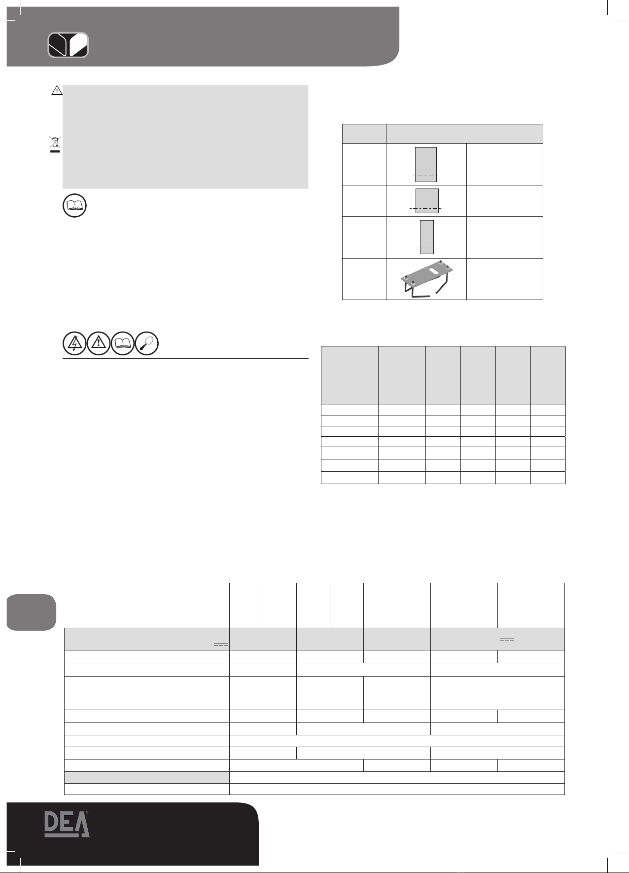
5 СПИСОК ЗАКАЗЫВАЕМЫХ ЗАПЧАСТЕЙ
Список заказываемых запчастей ( стр. 28, 29 и33) -это
подробный перечень, который сопровождает покомпонентный чертёж
изделия и который должен использоваться при заказе запчастей.
В таком документе кроме прочего указывается:
•код изделия(который можно узнать из этикетки изделия;смотрите
иллюстрацию F5 стр 31),
• номер позиции части изделия на покомпонентном чертеже,
•если имеется в наличии,может быть полезной дата
приобретения изделия.
6 СИСТЕМА ПОЛНОГО ЗАКРЫВАНИЯ
Данная глава, описывающая монтаж автоматического привода,
составлена с целью информировать и помочь монтажнику в выборе
различных компонентов согласно Директивы на Машины (2006/42/
CE) и Европейских нормативных актов касательно безопасности (EN
14453 - EN 12445) при монтаже ворот.
Данные, содержащиеся в главе, не имеют своей целью быть
полными и исчерпывающими. DEA System не несёт какую-либо
ответственность за возможные ошибки, упущения или неточности.
6.1 Защита предохранительной кромки
Среди самых значительных рисков, которые необходимо учитывать
для автоматического привода откатных ворот-это зажатие между
воротами и их створкой и/или другими существующими
неподвижными частями. Во избежание данного риска согласно
обозначенным стандартам необходимо использовать соответствующий
тип платы управления в зависимости от целей применения, для
которых предназначены ворота (смотрите таблицу “ОПЕРАТИВНОЕ
УПРАВЛЕНИЕ”).
6.2 Зажатие в зоне открывания
Возможный риск зажатия присутствует в зоне между воротами при
открывании и обычно стеной ограждения или другим препятствием. На
иллюстрации F10 стр. 32 приведены размеры, которые необходимо
соблюдать, когда не учитываются ограничения динамических усилий
или когда не используются системы обнаружения препятствия.
6.3 Удар в зоне закрывания
Во избежание риска динамического удара воротами людей в зоне
закрывания установите пару фотоэлементов с одной или другой
стороны или с обеих сторон (рекомендуемая высота 500 мм), так чтобы
можно было обнаружить присутствие препятствия по испытательному
параллелепипеду (высота 700 мм), расположенному, как указано на
иллюстрации F11 стр. 32. Примечание.Образец для обнаружения
перпятствия представляете собой параллелепипед, имеющий 3 светлые
и отражающие плоскости и 3 тёмные матовые плоскости.