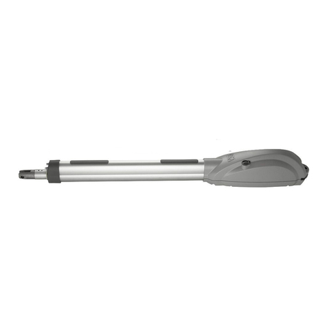
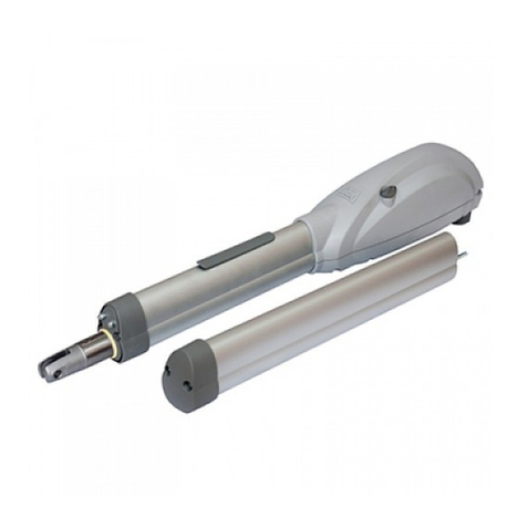
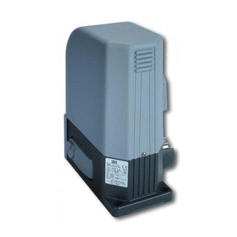
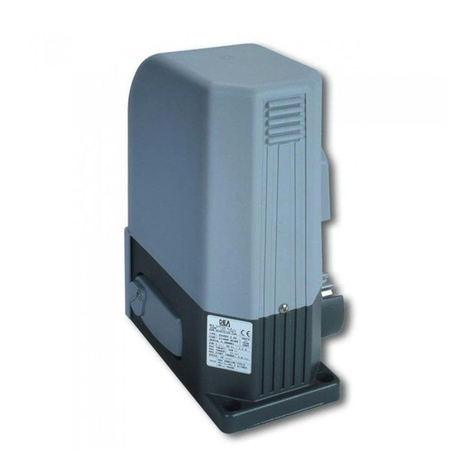
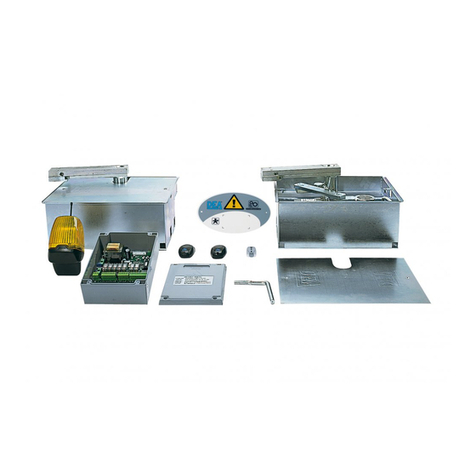
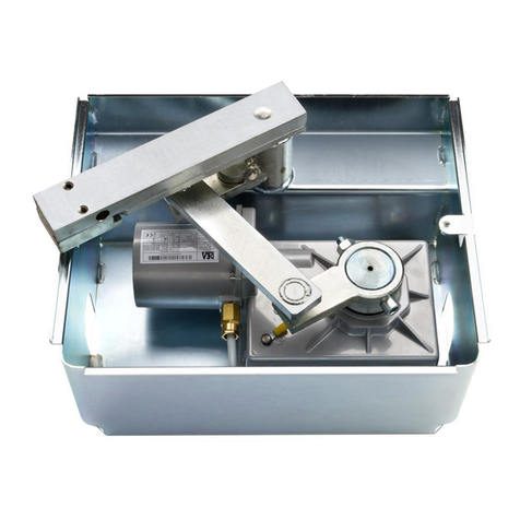
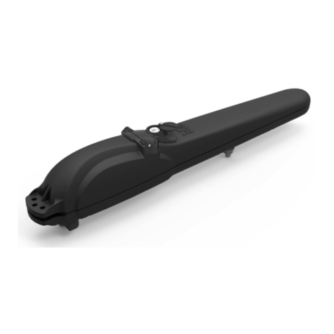
Dea OLI 600 User manual

OLI 600
Operatore oleodinamico per cancelli ad anta battente
Istruzioni d’uso ed avvertenze
Hydraulic operator for swing gates
Operating instructions and warnings
Opérateur hydraulique pour portails battants
Notice d’emploi et avertissements
Operador oleodinámico para puertas con hoja batiente
Instrucciones de uso y advertencias
Operador hidráulico para portões de folha batente
Instruções para utilização e advertências
BATTENTE
I6240XX Rev 07 18-06-10

Avvertimento
Warning
Avertissement
Advertencia
Advertência
Pericolo
Danger
Danger
Peligro
Perigo
Consultazione
Consultation
Consultation
Consultación
Consulta
Osservazione
Observation
Observation
Observación
Observação
Ispezione
Inspection
Inspection
Inspección
Inspecção
Certificazione
Certification
Certification
Certificación
Certificado
UTILIZZO DEL LIBRETTO
Per facilitare la comunicazione e la rintracciabilità di particolari
importanti informazioni all’interno del testo DEA System adotta la
simbologia riportata.
USE OF THIS BOOKLET
In order to facilitate communication and the traceability of parti-
cularly important parts of the text, DEA System adopts the symbols
provided.
UTILISATION DE CE LIVRET
Pour faciliter la communication et le repérage de renseignements
spéciaux et importants à l’intérieur du texte, DEA System a adopté
la symbologie indiquée.
UTILIZACIÓN DEL MANUAL
Para facilitar la comunicación y la trazabilidad de informaciones de
particular importancia, DEA System adopta, en el interior del texto,
la simbología reproducida.
UTILIZAÇÃO DO FOLHETO
Para facilitar a comunicação e localizar pormenores importantes de
informações no interior do texto, a DEA System adoptou os símbo-
los apresentados.

DICHIARAZIONE DI CONFORMITA’
DECLARATION OF CONFORMITY
DECLARATION DE CONFORMTÉ
DECLARACIÓN DE CONFORMIDAD
DECLARAÇÃO DE CONFORMIDADE
Il sottoscritto, rappresentante il seguente costruttore
The undersigned, representative of following manufacturer
Le soussigné, représentant le fabricant suivant
El abajo firmante, representante el fabricante siguiente
O abaixo-assinado, representando o seguinte construtor
DEA SYSTEM S.p.A.
Via Della Tecnica, 6
36013 PIOVENE ROCCHETTE (VI) - ITALY
dichiara che gli apparecchi denominati
hereby certifies that the equipment known as
déclare que les appareils nommés
declara que los equipos denominados
declara que os aparelhos denominados
602, 603, 604, 605, 606, 602L, 603L, 604L, 605L, 606L
Operatore oleodinamico per cancelli ad anta battente
Hydraulic operator for swing gates
Opérateur hydraulique pour portails battants
Operador oleodinámico para puertas con hoja batiente
Operador hidráulico para portões de folha batente
sono conformi alle disposizioni legislative che traspongono le seguenti Direttive
conform to the laws and regulations that comply with the following Directives
sont conformes aux termes des lois qui respectent les Directives suivantes
son conformes con las disposiciones legislativas que incorporan las siguientes Directivas:
são em conformidade as disposições de lei que respeitan as Directivas seguint es
• Direttiva2006/42/CE(DirettivaMacchine)
• Direttiva2006/95/CE(DirettivaBassaTensione)
• Direttiva2004/108/CE(DirettivaEMC)
e che sono state applicate le norme e/o specifiche tecniche di seguito indicate
and that the following norms and/or technical specification have been applied
et que les normes et/ou prescriptions techniques suivantes ont étés appliquées
y que se han aplicado las normas y/o especificaciones técnicas indicadas a continuación:
e que foram aplicadas as normas e/ou especificações técnicas indicadas a seguir:
ENISO12100-1:2003;ENISO12100-2:2003;ENISO13857:2008;EN349:1993+A1:2008;EN12635:2002+
A1:2008;ENISO13849-1:2008;ENISO14121-1:2007
EN60335-1:2002+A11:2004+A1:2004+A12:2006+A2:2006.
EN61000-6-2:2005;EN61000-6-3:2007.
Il sottoscritto dichiara che i prodotti elencati sopra non possono essere messi in funzione prima che la mac-
china sulla quale sono installati sia stata marcata CE in conformità a tutte le Direttive applicabili.
The underwritten declares that the above-mentioned products cannot be put into service unless the machinery
they are installed on carry the EC Mark in conformity to all applicable Directives.
Le soussigné déclare que les produits énumérés ci-dessus ne peuvent pas être mis en service avant que la
machine sur la quelle ils sont installés soit marquée CE en conformité à toutes les Directives applicables.
El suscrito declara que los productos arriba mencionados pueden ponerse en funcionamiento exclusivamente
después de que la máquina en la que han sido instalados haya sido marcada CE en conformidad con todas
las Directivas de aplicación.
O abaixo-assinado declara que os produtos citados acima, não podem ser colocados em função antes que
a máquina na qual estão instalados foram marcada CE em conformidade a todas as Directivas aplicaveis.
PIOVENE ROCCHETTE (VI) ITALY, 04/02/09
LIEVORE TIZIANO
Amministratore

OLI 600
Istruzionid’usoedavvertenze
2
SOMMARIO
Dichiarazione del fabbricante........................1
PREMESSA .......................................................2
1 CONFORMITÀ DEL PRODOTTO........................2
2 RIEPILOGO AVVERTENZE IN MERITO
AI RISCHI RESIDUI...........................................2
3 MODELLI E CONTENUTO DELL’IMBALLO.........3
4 ISTRUZIONI PER L’USO ...................................3
4.1 Descrizione del prodotto .......................3
4.2 Dati tecnici .............................................3
4.3 Riepilogo indicazioni per la marcatura 3
4.4 Condizionidiutilizzazionepreviste ......3
4.5 Istruzioni per eseguire senza rischio ....4
4.5.1 Trasporto – 4
4.5.2 Installazione, montaggio
e smontaggio – 4
4.5.3 Messa in funzione – 4
4.5.4 Impiego ed utilizzazione – 4
4.5.5 Regolazione – 4
4.5.6 Manutenzione e riparazione – 5
4.6 Addestramento......................................5
4.7 Controindicazionidiutilizzazione.........5
5 LISTA PARTI ORDINABILI.................................5
6 ASSIEME COMPLETO DELLA CHIUSURA ..........5
6.1 Livellominimodiprotezione
del bordo principale..............................6
6.2 Impatto e schiacciamento
nell’area di apertura.............................6
6.3 Impatto nell’area di chiusura
o di apertura .........................................6
Esempio di installazion tipica..............32
ALLEGATI
- Istruzioni per l’utente finale
- Condizioni di Garanzia
PREMESSA
SCOPO DELLE ISTRUZIONI
Queste istruzioni sono state redatte dal costruttore e sono
parte integrante del prodotto. Le operazioni contenute sono
dirette ad operatori adeguatamente formati ed abilitati. Si rac-
comanda di leggerle e conservarle per un riferimento futuro.
I capitoli “2 RIEPILOGO AVVERTENZE IN MERITO AI RISCHI
RESIDUI” e “4 ISTRUZIONI PER L’USO” contengono le infor-
mazioni che DEA System fornisce in modo tale che il prodotto
soddisfi sempre i Requisiti Essenziali di Sicurezza previsti dalla
Direttiva Macchine (Direttiva Europea 2006/42/CE).
Leggere attentamente questi capitoli in quanto forniscono
importanti istruzioni per la sicurezza d’installazione, d’uso e
di manutenzione ed importanti avvertenze in merito ai rischi
residui che permangono malgrado siano adottate tutte le dispo-
sizioni descritte.
Il prodotto è destinato ad essere incorporato in sistemi
completi di chiusura per i quali si applicano specifici riferimenti
legislativi. Il capitolo “6 ASSIEME COMPLETO DELLA CHIUSU-
RA” fornisce alcune indicazioni utili per il rispetto dei Requisiti
Essenziali di Sicurezza per particolari tipologie di chiusure.
1 CONFORMITÀ DEL PRODOTTO
OLI 600 è un prodotto marcato CE. DEA System as-
sicura la conformità del prodotto alle Direttive Europee
2006/42/CE sicurezza macchine, 2004/108/CE compa-
tibilità elettromagnetica e 2006/95/CE apparecchi elet-
trici a bassa tensione. DEA System allega alle presen-
ti istruzioni la Dichiarazione del Fabbricante (Cfr Direttiva
2006/42/CE Art. 4 comma 2).
2 RIEPILOGO AVVERTENZE
IN MERITO AI RISCHI RESIDUI
Leggere attentamente; la mancanza del rispetto delle se-
guenti avvertenze, può generare situazioni di pericolo. In par-
ticolare il costruttore raccomanda il rispetto dell “ATTENZIONE
A5” sull’importanza di non togliere la guarnizione OR di tenuta
sul gruppo maniglia.
ATTENZIONE L’utilizzo del prodotto in condizioni anomale
non previste dal costruttore può generare situazioni di perico-
lo; rispettare le condizioni previste dalle presenti istruzioni. A1
ATTENZIONE In nessun caso utilizzare il prodotto in presen-
za di atmosfera eplosiva. In nessun caso utilizzare il prodotto
in ambienti che possono essere agressivi e danneggiare parti
del prodotto. A2
ATTENZIONE L’utilizzo di parti di ricambio non indicate da
DEA System e/o il riassemblaggio non corretto possono cau-
sare situazioni di pericolo per persone, animali e cose; pos-
sono inoltre causare malfunzionamenti al prodotto; utilizzare
sempre le parti indicate da DEA System e seguire le istruzioni
per l’assemblaggio.
ATTENZIONE Eseguire lo smontaggio dell’operatore dai
propri attacchi solo dopo essersi assicurati che non vi sia
pressione all’interno della pompa/cilindro. A4
ATTENZIONE Se viene tolta la guarnizione OR di tenuta sul
gruppo maniglia ci può essere infiltrazione di acqua nel ser-
batoio dell’olio che può generare malfunzionamento e danno
al prodotto. Assicurarsi sempre che sia presente. A5
ATTENZIONE Il tappo di chiusura del profilo a protezione
dello stelo (vedi punto 1 in F1 pag. 30) è stato progettato per
garantire la sicurezza contro lo schiacciamento delle dita. In
nessun caso alterare tale dispositivo, per esempio fissandolo
con viti. Può essere pericoloso! A6
ATTENZIONE Durante l’operazione di regolazione è pos-
sibile l’infiltrazione d’acqua o di altre sostanze all’interno
del serbatoio d’olio. Ciò può causare danno e malfunziona-
mento della pompa. Prestare particolare attenzione a corpi
estranei nelle vicinanze e riposizionare la leva di sblocco a
regolazione avvenuta!! A7
ATTENZIONE Altre operazioni di regolazione/taratura
diverse dalla regolazione della portata sono eseguite dal
produttore. L’intervento su queste può causare malfunziona-
mento e/o situazioni di pericolo per persone, animali e cose.
Evitare ogni intervento non autorizzato da DEA System. A8
OLI 600
Operatore oleodinamico per cancelli ad anta battente
Istruzioni d’uso ed avvertenze ITALIANO

OLI 600
Istruzionid’usoedavvertenze
3
ATTENZIONE In ottemperanza alla Direttiva UE 2002/96/
EC sui rifiuti di apparecchiature elettriche ed elettroniche
(RAEE), questo prodotto elettrico non deve essere smaltito
come rifiuto municipale misto. Si prega di smaltire il prodotto
portandolo al punto di raccolta municipale locale per un op-
portuno riciclaggio.
ATTENZIONE La conoscenza del funzionamento dello sbloc-
co a chiave (vedi F4 pag. 30) di OLI 600 è molto importante
per tutti gli utenti dell’automatismo in quanto, in momenti di
emergenza, la mancanza di tempestività nell’agire su tale di-
spositivo può causare situazioni di pericolo. L’allegato I delle
presenti istruzioni è una pagina staccabile che ne illustra il
funzionamento; l’installatore è tenuto a consegnarla all’uten-
te finale. A10
3 MODELLI E CONTENUTO
DELL’IMBALLO
Con la denominazione OLI 600 viene identificata una fa-
miglia di operatori oleodinamici con caratteristiche diverse per
quanto riguarda la dimensione (corsa), la velocità, la reversibi-
lità e il blocco.
Gli articoli DEA System che compongono la serie sono:
Articolo n°blocchi/
revers. corsa velocità
602 1 (chiusura) 270 veloce
603 2 270 veloce
604 reversibile 270 veloce
605 2 400 veloce
606 reversibile 400 veloce
602L 1 (chiusura) 270 lento
603L 2 270 lento
604L reversibile 270 lento
605L 2 400 lento
606L reversibile 400 lento
OLI 600 è completato da una serie di accessori opzionali
che riportiamo:
Articolo Descrizione
0/652 Supporti di fissaggio
con piastra saldata
0/653 Supporti di fissaggio
standard
0/351 Piastra 100x60
600 H Olio idraulico 1 litro
Ispeziona il “Contenuto dell’imballo” a pag. 30 confrontan-
dolo con il tuo prodotto, ti potrà essere utile durante l’assem-
blaggio.
4 ISTRUZIONI PER L’USO
Contenuto conforme a quanto prescritto dalla Direttiva
2006/42/CE Allegato I punto 1.7.4.
4.1. Descrizione del prodotto
OLI 600 è un operatore oleodinamico per l’automatismo di
cancelli ad anta. E’ costituito essenzialmente da una pompa in
bagno d’olio che aziona un cilindro. La pompa è azionata da
un motore elettrico monofase (vedi F1 pag. 30).
4.2. Dati tecnici
Tensione di alimentazione monofase 230 V ±10% 50 Hz
Potenza assorbita 170 Watt
Pressione max 40 bar
Pressione nominale di esercizio 20 bar
Ciclo di lavoro intensivo
Forza di spinta a 20 bar 3200 N
Forza di trazione a 20 bar 2600 N
Corsa max 270 / 400 mm
Interasse max attacchi 1000 mm
Peso del prodotto con olio
OLI 602, 603, 604
OLI 605, 606 11,4 Kg
13,0 Kg
Tipo olio MOBIL DTE 11 M
Quantità olio OLI 602, 603, 604
OLI 605, 606 1,75 lt
2 lt
Temperature ambiente limite
di funzionamento -15°C ÷ 70 °C
Grado di protezione IP 55
Dimensioni di ingombro vedi F2 pag. 31
4.3. Riepilogo indicazioni per la marcatura
I dati riepilogativi per la marcatura CE sono riportati in parte
nell’etichetta applicata al prodotto (vedi posizione in F6 pag.
32); i dati del venditore sono riportati sulla Garanzia allegata.
Al punto “4.2 Dati tecnici” sono evidenziate tutte le “carat-
teristiche indispensabili alla sicurezza d’esercizio”.
4.4. Condizioni di utilizzazione previste
OLI 600 è un prodotto destinato ad essere installato su cancelli
ad anta battente civili ed industriali come attuatore per l’automa-
tismo di funzionamento come illustrato in F3 pag. 31.
Sono stati predisposti attacchi per il suo impiego su supporti
murari o strutture di carpenteria e su vari tipi di cancelli (vedi
tabella accessori opzionali pag. 3).
L’ambiente per il quale OLI 600 è stato progettato e testato è
la “normale” situazione per aperture civili ed industriali;i limiti di
temperatura, il grado di protezione da polvere ed acqua e altri
dati sono contenuti in “4.2 Dati tecnici”.
Un corretto posizionamento di OLI 600 rispetto al cancello è
indispensabile per il funzionamento; ecco le misure consigliate
da DEA System (vedi F3 pag. 31).
Articolo αA
mm B
mm C
mm D
mm E
mm
602 90° 130 130 270 1000 110
603 90° 130 130 270 1000 110
604 90° 130 130 270 1000 110
605 90° 200 190 400 1260 90
605 120° 150 190 400 1260 90
606 90° 200 190 400 1260 90
606 120° 150 190 400 1260 90

OLI 600
Istruzionid’usoedavvertenze
4
La scelta dell’automatismo va chiaramente fatta in funzione
del cancello da movimentare; l’attrito degli attacchi, il peso, la
lunghezza/altezza dell’anta, il grado di chiusura della superficie
sono gli elementi da considerare. Presentiamo sotto un grafico
indicativo che può essere d’aiuto per situazioni tipiche che mette
in relazione la lunghezza dell’anta con il suo peso.
ATTENZIONE L’utilizzo del prodotto in condizioni anomale
non previste dal costruttore può generare situazioni di perico-
lo; rispettare le condizioni previste dalle presenti istruzioni. A1
4.5. Istruzioni per eseguire senza rischio
4.5.1. Trasporto
OLI 600 è sempre fornito imballato in scatole che forniscono
una adeguata protezione al prodotto; fare comunque attenzione
a tutte le indicazioni eventualmente fornite sulla scatola stessa
per lo stoccaggio e la manipolazione.
Se si rendesse necessario per qualsiasi motivo il reimballo
ed il trasposto del prodotto dopo la sua installazione prestare
particolare attenzione alle possibili perdite d’olio dalla leva di
sblocco. Per evitare ciò controllare la presenza ed il corretto
posizionamento della guarnizione OR di tenuta sul gruppo ma-
niglia (vedi A in F5 pag. 30).
4.5.2. Installazione, montaggio e smontaggio
ATTENZIONE Qualsiasi operazione d’installazione, manu-
tenzione, pulizia o riparazione dell’intero impianto devono
essere eseguite esclusivamente da personale qualificato;
operare sempre in mancanza di alimentazione e seguire scru-
polosamente tutte le norme vigenti nel paese in cui si effettua
l’installazione, in materia di impianti elettrici. A3
Per una soddisfacente posa in opera del prodotto è impor-
tante:
• definireilprogettocompletodell’aperturaautomatica(fare
riferimento anche a “6 Assieme completo della chiusura); in
particolare, dopo aver valutato con attenzione le caratteri-
stiche dei supporti e del cancello designare tipo e posizione
degli attacchi in funzione anche dell’angolo di apertura che
si vuole ottenere (vedi F2, F3 pag. 31);
• fissaregliattacchi.
Il fissaggio degli attacchi va eseguito con particolare attenzio-
ne sia su pilastri in ferro e muratura sia su cancelli di ogni tipo.
Nei pilastri in ferro e nei cancelli, è importante valutare con
attenzione la necessità di applicare un fazzoletto di rinforzo,
questo si rende necessario soprattutto quando la struttura è
debole; per esempio, quando la lamiera è sottile o quando la
morfologia stessa del cancello è poco solida.
Nei pilastri in muratura, invece, è sempre necessario ap-
plicare un supporto a piastra saldata del tipo art. 0/652 DEA
System (vedi “3 Modelli e contenuto dell’imballo”) che viene
fissato, a seconda del tipo, annegato in una malta cementizia,
con fissaggio meccanico o con fissaggio chimico.
Proteggere bene le saldature dalla corrosione.
Fare particolare attenzione all’allineamento fra gli attacchi
ed alla loro orizzontalità. Applicare OLI 600 agli attacchi come
illustrato in F8 e F9 pag. 32.
ATTENZIONE Eseguire lo smontaggio dell’operatore dai
propri attacchi solo dopo essersi assicurati che non vi sia pres-
sione all’interno della pompa/cilindro. A4
4.5.3 Messa in funzione
Per l’installazione del prodotto è necessario eseguire opere
murarie e/o saldature e collegamenti elettrici; utilizzare attrez-
zatura adeguata al tipo di lavoro da svolgere e seguire tutte le
norme antinfortunistiche vigenti nel paese d’intallazione. Il pro-
dotto va collegato elettricamente generalemente ad una centra-
lina di comando per automatismi; fare riferimento alle istruzioni
di tale dispositivo per ulteriori informazioni. In caso si utilizzi
una centrale di comando 202RR, fare riferimento alla
procedurariportataapag.7.
Per evitare la fuoriuscita dell’olio dall’operatore durante il
trasporto e per garantire una adeguata protezione contro l’infil-
trazione di acqua nel prodotto DEA System installa una guarni-
zione OR di tenuta sul gruppo maniglia (vedi A in F5 pag. 30).
ATTENZIONE Se viene tolta la guarnizione OR di tenuta sul
gruppo maniglia ci può essere infiltrazione di acqua nel ser-
batoio dell’olio che può generare malfunzionamento e danno
al prodotto. Assicurarsi sempre che sia presente. A5
4.5.4. Impiego ed utilizzazione
Il prodotto è destinato ad essere parte di un assieme di ap-
parecchi che nel loro complesso realizzano l’automatismo del
cancello. DEA System presuppone che il suo utilizzo sia sempre
conforme a quanto prescritto dalla normativa vigente.
OLI 600 è dotato di un dispositivo di sblocco; il funziona-
mento di tale dispositivo è il seguente.
Una volta aperta la serratura posta sulla maniglia (protetta
dal coperchietto in plastica nera) la leva va azionata in senso
orario fino alla fine della sua corsa (per 90° circa); a questo
punto OLI 600 è sbloccato e il cancello, in assenza di altri im-
pedimenti è libero nei suoi movimenti. Il procedimento inverso,
rotazione della leva fino a fine corsa (per 90° circa) in senso
antiorario e chiusura della serratura (ricordarsi di proteggere
la serratura con l’apposito coperchietto), riporta OLI 600 in
condizioni di lavoro.
ATTENZIONE Il tappo di chiusura del profilo a protezione
dello stelo (vedi punto 1 in F1 pag. 30) è stato progettato per
garantire la sicurezza contro lo schiacciamento delle dita. In
nessun caso alterare tale dispositivo, per esempio fissandolo
con viti. Può essere pericoloso! A6
4.5.5. Regolazione
La pompa è dotata di una coppia di valvole per la rego-
lazione della portata in apertura e chiusura. Per accedere alla
regolazione è necessario togliere le due viti di fissaggio della
leva di sblocco (vedi F5 pag. 30).
Per eliminare eventuale presenza di aria nel cilindro, dopo
aver eseguito la regolazione, effettuare un ciclo completo di aper-
tura fino a finecorsa e agire sullo sblocco manuale. Ripetere tale
operazione anche per un ciclo completo di chiusura. Eseguire
questi interventi per 2 o 3 volte. (vedere anche F12 pag. 37).
ATTENZIONE Durante l’operazione di regolazione è possi-
bile l’infiltrazione d’acqua o di altre sostanze all’interno del
serbatoio d’olio. Ciò può causare danno e malfunzionamento
della pompa. Prestare particolare attenzione a corpi estranei
nelle vicinanze e riposizionare la leva di sblocco a regolazione
avvenuta!! A7
ATTENZIONE Altre operazioni di regolazione/taratura diver-
se dalla regolazione della portata sono eseguite dal produtto-
re. L’intervento su queste può causare malfunzionamento e/o
situazioni di pericolo per persone, animali e cose. Evitare ogni
intervento non autorizzato da DEA System. A8
Grafico “LUNGHEZZA - PESO”
OLI 600
Istruzionid’usoedavvertenze
5
4.5.6. Manutenzione e riparazione
Una buona manutenzione preventiva ed una regolare ispe-
zione al prodotto ne assicurano una lunga durata (vedi anche
“Garanzia”). In caso di guasto si può far riferimento alla tabella
“GUIDA RICERCA GUASTI” qui a lato per cercare una soluzione
al problema; se i consigli riportati non portano alla soluzione
contattare DEA System.
Le operazioni di ispezione/manutenzione che sono da
programmare sul “registro di manutenzione dell’automazione
completa” sono:
TIPO DI INTERVENTO PERIODICITA’
pulizia superfici esterne 6 mesi
controllo serraggio viti 6 mesi
controllo funzionamento dello sblocco 6 mesi
controllo livello olio 1 anno
sostituzione olio 3 anni
ingrassaggio giunto a snodo 1 anno
Sostituire l’olio fornito da DEA System dopo tre anni di utiliz-
zo con uno di ugual tipo (vedi “4.2 Dati tecnici”). Se, durante le
ispezioni si dovesse rilevare un livello insufficiente di olio, signifi-
ca che vi è una perdita; controllare bene tutte le chiusure, indivi-
duata la perdita risolvere il problema, se necessario richiedere a
DEA System parti di ricambio e/o assistenza. Per la sostituzione
dell’olio togliere la maniglia di sblocco, smontare OLI 600 da-
gli attacchi e rovesciarlo fino alla completa fuoriuscita dell’olio
presente (vedi F5, F8 e F9 pagg. 31 e 32). Rabboccare fino al
livello corretto dell’olio (vedi F7 pag 32).
ATTENZIONE Eseguire lo smontaggio dell’operatore dai
propri attacchi solo dopo essersi assicurati che non vi sia
pressione all’interno della pompa/cilindro. A4
ATTENZIONE Qualsiasi operazione d’installazione, manu-
tenzione, pulizia o riparazione dell’intero impianto devono
essere eseguite esclusivamente da personale qualificato;
operare sempre in mancanza di alimentazione e seguire scru-
polosamente tutte le norme vigenti nel paese in cui si effettua
l’installazione, in materia di impianti elettrici. A3
ATTENZIONE L’utilizzo di parti di ricambio non indicate da
DEA System e/o il riassemblaggio non corretto possono cau-
sare situazioni di pericolo per persone, animali e cose; pos-
sono inoltre causare malfunzionamenti al prodotto; utilizzare
sempre le parti indicate da DEA System e seguire le istruzioni
per l’assemblaggio. A9
4.6. Addestramento
Il funzionamento dell’automatismo completo, una volta
messo a punto dall’installatore, va attentamente illustrato al-
l’utente finale.
E’ importante, per quanto riguarda OLI 600, istruire sul fun-
zionamento dello sblocco (vedi “Allegati”) e su quale sia il pro-
gramma di manutenione che lo riguarda (vedi punto 4.5.6.).
ATTENZIONE La conoscenza del funzionamento dello sbloc-
co a chiave (vedi F4 pag. 30) di OLI 600 è molto importante
per tutti gli utenti dell’automatismo in quanto, in momenti di
emergenza, la mancanza di tempestività nell’agire su tale di-
spositivo può causare situazioni di pericolo. L’allegato I delle
presenti istruzioni è una pagina staccabile che ne illustra il
funzionamento; l’installatore è tenuto a consegnarla all’utente
finale. A10
4.7. Controindicazioni di utilizzazione
Al capitolo “4.4 Condizioni di utilizzazione previste” sono
state descritte le condizioni per le quali il prodotto è stato pro-
gettato e testato. Non utilizzare il prodotto per scopi diversi.
ATTENZIONE L’utilizzo del prodotto in condizioni anomale
non previste dal costruttore può generare situazioni di perico-
lo; rispettare le condizioni previste dalle presenti istruzioni. A1
ATTENZIONE In nessun caso utilizzare il prodotto in presen-
za di atmosfera eplosiva. In nessun caso utilizzare il prodotto
in ambienti che possono essere agressivi e danneggiare parti
del prodotto. A2
5 LISTA PARTI ORDINABILI
La lista delle parti ordinabili (pagg. 28 e 33) è un dettagliato
elenco che accompagna l’esploso del prodotto e che deve esse-
re utilizzata per l’ordine di parti di ricambio.
In tale documento va sempre indicato fra l’altro:
• ilcodicedelprodotto(ricavabiledall’etichettaprodotto;vedi
F6 pag 32),
• ilnumerodiposizionedellapartenell’esploso,
• sedisponibile,puòessereutileladatadiacquistodelpro-
dotto.
6 ASSIEME COMPLETO CHIUSURA
Questo capitolo, che illustra un’installazione tipo di un au-
tomatismo completo, viene redatto con lo scopo di informare
ed agevolare l’installatore nella scelta dei vari componenti nel
rispetto della Direttiva Macchine (2006/42/CE) e delle Normati-
ve Europee riguardanti la sicurezza (EN 12453 - EN 12445) per
l’intallazione dei cancelli. I dati riportati in questo capitolo non
hanno lo scopo di essere completi ed esaurienti. DEA System
non può assumersi alcuna responsabilità per eventuali errori,
omissioni o approssimazioni.
Tabella “GUIDA RICERCA GUASTI”
GUASTO CAUSA / RIMEDIO
Attivando il comando di apertura l’anta non si
muove ed il motore elettrico dell’operatore non
entra in funzione.
L’operatore non è correttamente alimentato; controllare i collegamenti,
i fusibili e le condizioni del cavo di alimentazione ed eventualmente
provvedere alla loro sostituzione/riparazione
Attivando il comando di apertura il motore en-
tra in funzione ma l’anta non si muove
Nel caso in cui l’operatore sia dotato di sblocco: controllare che sia chiu-
so (vedi F4 pag. 30) ed eventualmente regolare la pressione di apertura
e chiusura
Durante il movimento l’operatore funziona a
scatti
Probabile presenza di aria all’interno del cilindro; svincolare l’operatore
dall’attacco anteriore ed eseguire alcune manovre a vuoto, ripristinare
il collegamento.
Insufficiente quantità di olio all’interno del cilindro; ripristinare il livello
dell’olio (vedi F7 pag. 32) ed effettuare lo spurgo dell’aria eseguendo
alcune manovre a vuoto (come al punto precedente)
Gli attacchi, anteriore e posteriore, dell’operatore flettono o sono fissati
in modo inadeguato; ripararli e/o rinforzarli

OLI 600
Istruzionid’usoedavvertenze
6
6.1. Protezione del bordo principale
Tra i rischi più rilevanti che sono da considerare nell’automazione di un cancello ad
anta battente vi è quello di schiacciamento tra le due ante in chiusura, o tra di un’anta
e la sua battuta. Le norme citate prevedono che, per tale rischio, sia adottata una delle
seguenti tipologie di comando di attivazione in funzione della tipologia d’uso a cui il
cancello è destinato.
Nell’esempio di pagina precedente si è scelto di adottare un sistema con chiusura
sovrapposta e ritardata e la protezione dell’anta con un bordo sensibile.
6.2. Schiacciamento nell’area di apertura
Possibile rischio di schiacciamento c’è nella zona che sta tra il cancello in apertura e
tipicamente un muro di recinzione od altro ingombro. In F10 pag. 32 sono riportate le
misure che è necessario rispettare nel caso in qui non si ricorra alla limitazione delle forze
di impatto o a sistemi di rilevazione della presenza.
6.3. Impatto nell’area di chiusura o di apertura
Per evitare l’impatto di persone con l’anta nell’area di chiusura Installare una coppia
di fotocellule (A) (altezza consigliata 500 mm) in modo tale da rilevare la presenza del pa-
rallelepipedo di prova (B) (altezza 700 mm) posizionato come indicato in F11 pag. 32.
N.B. Il campione per la rilevazione di presenza è un parallelepipedo avente 3 facce
con superficie chiara e riflettente e 3 facce con superficie scura e opaca.
Per ridurre ulteriormente la possibilità di impatto con l’anta nell’area di apertura è
possibile installare, in aggiunta, una coppia di fotocellule (C) (altezza consigliata 500
mm) in modo tale da rilevare la presenza del parallelepipedo di prova (D) (altezza 700
mm) posizionato come indicato in F11 pag. 32.
L’INSTALLATORE DEVE
Si ricorda che chi vende e motorizza una
porta/cancello diventa il costruttore della
macchina porta/cancello automatico, e
deve predisporre e conservare il fascico-
lo tecnico che dovrà contenere i seguenti
documenti (vedi allegato V della Direttiva
Macchine).
• Disegno complessivo della porta/
cancello automatico.
• Schemadeicollegamentielettriciedei
circuiti di comando.
• Analisi dei rischi comprendente:
l’elenco dei requisiti essenziali previsti
nell’allegato I della Direttiva Macchi-
ne; l’elenco dei rischi presentati dalla
porta/cancello e la descrizione delle
soluzioni adottate.
• Conservare queste istruzioni d’uso;
conservare le istruzioni d’uso degli
altri componenti.
• Preparare le istruzioni per l’uso e le
avvertenze generali per la sicurezza
(completando queste istruzioni d’uso)
e consegnarne copia all’utilizzatore.
• Compilareilregistrodimanutenzione
e consegnarne copia all’utilizzatore.
• RedigereladichiarazioneCEdicon-
formità e consegnare copia all’utiliz-
zatore.
• Compilarel’etichettaolatargacom-
pleta di marcatura CE e applicarla
sulla porta/cancello.
N.B. Il fascicolo tecnico deve essere con-
servato e tenuto a disposizione delle auto-
rità nazionali competenti per almeno dieci
anni a decorrere dalla data di costruzione
della porta/cancello automatico.
1 5 6 7 8 9
2 3 410
Pos. Descrizione
1 Selettore a chiave
102 Lux
2 Colonnina Pilly 60
3 Radiocomando
4 Elettroserratura
5 Bordo sensibile
6 Selettore digitale
FLIC/rad
7 Fotocellule serie
104 Lux
8 OLI 600
9 Lampeggiante Lumy
10 Quadro di comando
Tipologia d’uso
Tipologia dei comandi di
attivazione Utenti informati
(area privata)
Utenti informati
(area pubblica)
Utenti non informati
Comando a uomo
presente
Controllo a pulsante Controllo a pulsante con
chiave Non è possibile il
comandoa uomo presente
Comando ad impulso con
la porta in vista
Limitazione delle forze,
oppure
Rilevatori di presenza
Limitazione delle forze,
oppure
Rilevatori di presenza
Limitazione delle forze e
Fotocellule, oppure
Rilevatori di presenza
Comando ad impulso con
la porta non in vista
Limitazione delle forze,
oppure
Rilevatori di presenza
Limitazione delle forze e
Fotocellule, oppure
Rilevatori di presenza
Limitazione delle forze e
Fotocellule, oppure
Rilevatori di presenza
Comando automatico
(ad esempio, il comando di
chiusura temporizzata)
Limitazione delle forze e
Fotocellule, oppure
Rilevatori di presenza
Limitazione delle forze e
Fotocellule, oppure
Rilevatori di presenza
Limitazione delle forze e
Fotocellule, oppure
Rilevatori di presenza
Figura “ESEMPIO DI INSTALLAZIONE TIPICA”

OLI 600
Istruzionid’usoedavvertenze
7
ISTRUZIONI PER LA CORRETTA REGOLAZIONE DI AUTOMATISMI CON PISTONE OLEODINAMICO E
CENTRALE DI COMANDO 202RR.
(prima di procedere leggere attentamente il manuale d’uso della centrale di comando 202RR)
L’utilizzo della centrale di comando 202RR in abbinamento agli attuatori oleodinamici “OLI”, prevede due diverse modalità di re-
golazione dell’impianto a seconda del tipo di installazione e dell’utilizzo previsto:
Regolazione meccanica della forza, (maggiore praticità e velocità di installazione):
1. Impostare sulla centrale di comando la forza dei motori quasi al massimo (P014 = P016 = 99%);
2. Accedere al parametro P.001, “posizionamento anta 1” e premendo i tasti “+/-” portare l’anta nella posizione di completa
apertura. Eventualmente regolare la forza del motore intervenendo sulle viti delle valvole di sfogo del motore;
3. Accedere al parametro P.002, “posizionamento anta 2” e premendo i tasti “+/-” portare l’anta nella posizione di completa
apertura. Eventualmente regolare la forza del motore intervenendo sulle viti delle valvole di sfogo del motore;
4. Accedere al P.003 ed avviare la manovra di apprendimento. Il motore 1 parte in chiusura e si arresta automaticamente all’arrivo
in battuta (se il motore non si arresta premere il tasto OK). Il motore 2 parte in chiusura e si arresta automaticamente all’arrivo
in battuta (se il motore non si arresta premere il tasto OK). Sul display compare “----“, apprendimento concluso.
Regolazione elettronica della forza, e taratura del dispositivo di rilevamento degli ostacoli (più elevato livello di sicurezza
dell’impianto):
1. Impostare la forza motore (P.014) ad un valore intermedio (50%) o più elevato nel caso di cancelli molto pesanti;
2. Allentare completamente entrambe le viti delle valvole di sfogo sul motore;
3. Accedere al parametro P.001, “posizionamento anta”;
4. Premere il tasto “+” (o il CH2 di un radiocomando precedentemente memorizzato): il motore si avvia, ma l’anta non si muove.
Mantenendo premuto il tasto, serrare la valvola di sfogo di apertura fino a quando il motore inizia ad aprire con la forza desi-
derata;
5. Premere il tasto “-” (o il CH4 di un radiocomando precedentemente memorizzato): il motore si avvia, ma l’anta non si muove.
Mantenendo premuto il tasto, serrare la valvola di sfogo di chiusura fino a quando il motore inizia a chiudere con la forza de-
siderata;
6. Uscire dal parametro P.001 ed accedere al parametro P.014: diminuire la forza impostata, uscire dal P.014 ed accedere nuova-
mente al P.001 per verificare che il motore sia ancora in grado di muovere correttamente l’anta in entrambe le direzioni;
7. Ripetereilpunto6finoadindividuareilvaloreminimodiforzaingradodimuoverecorrettamentel’antain
entrambe le direzioni;
8. Accedere al P.001 e premendo il tasto “-” portare l’anta in battuta in chiusura. Mantenendo il tasto premuto serrare ulteriormen-
te la valvola di sfogo di chiusura fino a quando non si sente che la pompa si blocca completamente ed il motore è sottosfor-
zo;
9. Premendo il tasto “+” portare l’anta in battuta in apertura. Mantenendo il tasto premuto serrare ulteriormente la valvola di
sfogo di apertura fino a quando non si sente che la pompa si blocca completamente ed il motore è sottosforzo;
10.Lasciare l’anta completamente aperta;
11.Ripetere tutta la procedura dal punto 1 al 10 per l’anta n°2 utilizzando i parametri P.002 per il posizionamento e P.016 per la
regolazione della forza. Lasciare infine l’anta completamente aperta;
12.Accedere al P.003 ed avviare la manovra di apprendimento. La manovra si conclude automaticamente quando entrambe le
ante sono arrivate in battuta in chiusura e sul display compare “----“;
Nel caso in cui un’eventuale elettroserratura abbia difficoltà ad agganciarsi, durante la manovra di apprendimento facilitare
l’aggancio della stessa spingendo leggermente l’anta con le mani, dopodichè procedere come segue:
13.impostare P.031 “forza nell’ultimo tratto in chiusura” ad un valore pari al valore impostato per il P.014 aumentato di circa il 30%
(es.: se P0.14 = 50, allora P.031 = 65);
14.Avviare una manovra di chiusura e quando l’anta n°1 arriva in battuta, prima che il tempo di lavoro si concluda, serrare ulte-
riormente la valvola di sfogo di chiusura fino a quando l’elettroserratura si aggancia.

OLI 600
Operating instructions and warnings
8
INDEX
Declaration by manufacturer .........................1
OVERVIEW.......................................................8
1 PRODUCT CONFORMITY..................................8
2 RESIDUAL RISK WARNINGS ............................8
3 MODELS AND CONTENTS OF THE PACKAGE...9
4 OPERATING INSTRUCTIONS ...........................9
4.1 Product description................................9
4.2 Technical data........................................9
4.3 Labelling information............................9
4.4 Suitable conditions of use .....................9
4.5 Instructions for risk-free operation .....10
4.5.1 Transport – 10
4.5.2 Installation, assembly
and disassembly – 10
4.5.3 Starting – 10
4.5.4 Use – 10
4.5.5 Adjustment – 10
4.5.6 Maintenance and repair – 10
4.6 Training ...............................................11
4.7 Notsuitableuse...................................11
5 SPARE PARTS LIST..........................................11
6 COMPLETE CLOSING ASSEMBLY ...................11
6.1 Minimumlevelofprotection
providedbythesafetyedge................11
6.2 Crushing in the opening area .............11
6.3 Impactintheopening/closingarea....12
Example of typical installation ............32
ANNEXES
- Instructions for the final user
- Terms of warranty
OVERVIEW
SCOPE OF THE INSTRUCTIONS
These instructions were prepared by the manufacturer and
are an integral part of the product. The operations described are
intended for adequately trained and qualified users and must be
carefully read and conserved for future reference.
Chapters “2 RESIDUAL RISK WARNINGS” and “4 OPERA-
TING INSTRUCTIONS” contain all the information that DEA
System provides in order for the product to constantly satisfy
the Essential Safety Requirements prescribed by the Machinery
Directive (European Directive 2006/42/CE).
Read these chapters carefully because they contain impor-
tant instructions for safe installation, use and maintenance and
important warnings regarding the residual risks remaining even
after all the safety devices and measures described have been
applied.
The product is designed for installation in complete closing
systems subject to specific legislation. Chapter 6 “COMPLE-
TE CLOSING ASSEMBLY” provides useful information for the
respect of the Essential Safety Requisites for special types of
closing.
1 PRODUCT CONFORMITY
The OLI 600 hydraulic gate operator bears the CE label.
DEA System guarantees the conformity of the product to Eu-
ropean Directives 2006/42/CE regarding machinery safety,
2004/108/CE electromagnetic compatibility and 2006/95/CE
low voltage electrical equipment. DEA System also encloses the
manufacturer’s Declaration of Conformity with these instructions
(see Directive 2006/42/CE Art. 4, paragraph 2).
2 RESIDUAL RISK WARNINGS
Read these warnings carefully; the failure to respect the
following warnings can create risk situations. In particular, the
manufacturer urges the absolute respect of “WARNING A5”
regarding the importance of not removing the O-ring in the
release mechanism.
WARNING The use of the product under unusual conditions
not foreseen by the manufacturer can create situations of
danger, and for this reason all the conditions prescribed in
these instructions must be respected. A1
WARNING Under no circumstances must the product be
used in explosive atmospheres or surroundings that may pro-
ve corrosive and damage parts of the product. A2
WARNING The use of spare parts not indicated by DEA Sy-
stem and/or incorrect re-assembly can create risk to people,
animals and property and also damage the product. For this
reason, always use only the parts indicated by DEA System
and scrupulously follow all assembly instructions.
WARNING Disassemble the gate operator from its attach-
ments only after first making sure that there is no pressure
remaining inside the pump/cylinder. A4
WARNING The removal of the O-ring in the release mecha-
nism may cause water infiltrations into the oil tank, which
may damage the product or result in malfunctioning. Always
make sure the O-ring is installed. A5
WARNING The stopper that protects the rod (see Point 1
in F1 Page 30) has been designed to guarantee protection
against the crushing of the fingers. Under no circumstances
must this device be tampered with by locking it in place with
screws, for example, thereby creating serious risk! A6
WARNING Water or other substances may enter the oil tank
during adjustment operations and cause pump damage and
malfunction. Therefore pay careful attention to any such fo-
reign matter in the vicinity and remember to re-position the
release lever after adjustment has been completed. A7
WARNING All the other adjustment/setting operations beyond
the adjustment of the oil flow are made by the manufacturer.
Tampering with these settings may cause malfunction and/or
situations of risk to people, animals and property. Refrain from
performing any operations not authorised by DEA System. A8
WARNING In line with EU Directive 2002/96/EC for waste
electrical and electronic equipment (WEEE), this electrical pro-
duct must not be disposed of as unsorted municipal waste.
Please dispose of this product by returning it to your local
municipal collection point for recycling.
OLI 600
Hydraulic operator for swing gates
Operating instructions and warnings ENGLISH

OLI 600
Operating instructions and warnings
9
WARNING Awareness of the operation of the OLI 600 key-
release mechanism (see F4 Page 30) is essential for all users
of the automatism because the failure to use the device qui-
ckly during emergencies can jeopardise people, animals and
property. Enclosure I to these instructions, which the installer
is required to deliver to the final user, illustrates operation and
can be detached. A10
3 MODELS AND CONTENTS
OF THE PACKAGE
The name OLI 600 identifies a series of hydraulic gate ope-
rators with different features depending on dimension (stroke),
speed, reversibility, and blocks.
The DEA System articles in the series are:
Article No.ofblocks/
revers. stroke speed
602 1 (closing) 270 fast
603 2 270 fast
604 reversible 270 fast
605 2 400 fast
606 reversible 400 fast
602L 1 (closing) 270 slow
603L 2 270 slow
604L reversible 270 slow
605L 2 400 slow
606L reversible 400 slow
The OLI 600 gate operator is completed by the set of optio-
nal accessories below:
Article Description
0/652 Fastening supports with
welded plate
0/653 Standard fastening
supports
0/351 Plate 100x60
600 H Hydraulic oil: 1 liter
Inspect the “Contents of the Package” on Page 30 and
compare it with your product for useful consultation during
assembly.
4 OPERATING INSTRUCTIONS
In compliance with Directive 2006/42/CE Enclosure I, Point
1.7.4.
4.1 Product description
The OLI 600 hydraulic operator for swing gate automation
is composed essentially by a pump in an oil bath that drives a
cylinder. The pump is driven by a single-phase electric motor
(see F1, Page 30).
4.2 Technical data
Single-phase power supply 230 V ±10% 50 Hz
Absorbed power 170 Watt
Max. pressure 40 bar
Rated operating pressure 20 bar
Work cycle intensive
Thrust force at 20 Bar 3200 N
Traction force at 20 Bar 2600 N
Max. stroke 270 / 400 mm
Max. distance between
attachments 1000 mm
Weight of product filled with oil
OLI 602, 603, 604
OLI 605, 606 11,4 Kg
13,0 Kg
Type of oil MOBIL DTE 11 M
Quantity of oil OLI 602, 603, 604
OLI 605, 606 1,75 lt
2 lt
Operating temperature range -15°C ÷ 70 °C
Degree of protection IP 55
Overall dimensions see F2 on page 31
4.3 Labelling information
Part of the summarised data for the CE label are listed in the
label applied to the product (see Position F6, Page 32); the data
regarding the seller are found in the enclosed Warranty, while
“Indispensable Operating Safety Elements” are found under
Point “4.2 Technical data”.
4.4 Suitable conditions of use
The OLI 600 is designed for installation in residential and
industrial swing gates as an actuator for the operational auto-
mation as shown in F3 on Page 31 and features attachments
for its use on supports in masonry or metal structural works and
various types of gates (see the optional accessories table on
Page 8).
The OLI 600 has been designed and tested for operation un-
der “normal” residential and industrial gate opening conditions;
temperature limits, degrees of protection against dust and water,
and other data are provided in Point 4.2 “Technical Data”.
Satisfactory operation requires the correct positioning of the
OLI 600 operator with respect to the gate; we provide the DEA
System recommended measurements in F3, Page 31.
Article αA
mm B
mm C
mm D
mm E
mm
602 90° 130 130 270 1000 110
603 90° 130 130 270 1000 110
604 90° 130 130 270 1000 110
605 90° 200 190 400 1260 90
605 120° 150 190 400 1260 90
606 90° 200 190 400 1260 90
606 120° 150 190 400 1260 90
The operator required must be selected according to the
gate to be automated; the attrition on the attachments, the wei-
ght, the length/height of the gate leaf and the degree of closing
of the surfaces are the elements to be considered. We provide a
chart representing typical situations that correlates the length of
the gate leaf with its weight.

OLI 600
Operating instructions and warnings
10
WARNING The use of the product under unusual conditions
not foreseen by the manufacturer can create situations of dan-
ger, and for this reason all the conditions prescribed in these
instructions must be respected. A1
4.5 Instructions for risk-free operation
4.5.1 Transport
The OLI 600 gate operator is always delivered packed in
boxes that guarantee the product adequate protection. Care-
fully read any warnings or instructions for storage and handling
provided on the box. If the product must be re-packaged or
transported for any reason after installation, consider the risk of
leakage of oil from the release lever. To avoid this make sure the
O-ring is installed and appropriately positioned in the release
mechanism (see A in F5 on Page 30).
4.5.2 Installation, assembly and disassembly
WARNING All installation, maintenance, cleaning or repair
operations on any part of the system must be performed exclu-
sively by qualified personnel with the power supply discon-
nected working in strict compliance with the electrical standar-
ds and regulations in force in the nation of installation. A3
The following operations are essential to the correct laying
of the product:
• thecarefuldefinitionoftheentireautomaticopeninglayout
(see also “6 Complete Closing Assembly”); in particular,
after carefully assessing the characteristics of the supports
and the gate, the attachments must also be designed and
positioned according to the angle of opening desired (see
F2, F3 Page 31).
• fastentheattachments
The fastening of the attachments must be performed with
extra attention on both iron pillars and masonry works and gates
of any type.
The necessity of installing reinforcement plates for iron
pillars and gates must be carefully assessed whenever the re-
maining part of the structure does not appear sufficiently strong,
whenever the metal plate used does not appear thick enough or
whenever the morphology of the gate appears to lack solidity.
Pillars in masonry, on the other hand, always require the
application of a welded plate support, such as Art. 0/652 DEA
System (see “3 Models and contents of the package”) to be fa-
stened sunken in a cement mortar foundation, fastened mecha-
nically or chemically depending on type.
Keep all welding seams well protected from corrosion.
Give extra attention to the alignment between the attach-
ments and their planarity. Apply the OLI 600 gate operator to
the attachments as shown in F8 and F9 on Page 32.
WARNING Disassemble the gate operator from its attach-
ments only after first making sure that there is no pressure
remaining inside the pump/cylinder. A4
4.5.3 Starting
The installation of the product requires masonry and/or wel-
ding and electrical connection operations using adequate equi-
pment for the job in complete respect of the accident-prevention
standards and regulations in force in the nation of installation.
The product must be electrically connected to a special con-
trol unit for gate operators; see the instructions provided for such
device for further information. Refer to procedure on page
13 if you use a 202RR control panel.
In order to avoid all oil leakage from the operator during
transport and to ensure proper protection against water infiltra-
tion in the product, DEA System installs an O-ring in the release
mechanism (see A in F5 on Page 30).
WARNING The removal of the O-ring in the release mecha-
nism may cause water infiltrations into the oil tank, which
may damage the product or result in malfunctioning. Always
make sure the O-ring is installed. A5
4.5.4 Use
The product is destined for incorporation in the assembly of
devices that comprise the gate automation. DEA System assu-
mes that it will always be used in compliance with the standards
and regulations in force. The OLI 600 gate operator is equipped
with a release system with the following operation:
After the lock on the handle has been opened (protected by
the black plastic cover), the lever must be rotated clockwise to
the end of its stroke (to approx. 90°); at this point, the OLI 600
operator is released and if no other obstructions are present, the
gate is free to move without hindrance.
The opposite procedure, in other words, the rotation of the
lever to the end of its stroke (to approx. 90°) in the counter-
clockwise direction and the closing of the lock (remember to
protect the lock with the respective cover) returns the OLI 600
operator to normal working conditions.
WARNING The stopper that protects the rod (see Point 1 in F1
Page 30) has been designed to guarantee protection against
the crushing of the fingers. Under no circumstances must this
device be tampered with by locking it in place with screws, for
example, thereby creating serious risk! A6
4.5.5 Adjustment
The pump is equipped with a pair of valves for the adjustment
of the oil flow during opening and closing. Remove the release
lever’s two fixing screws to permit adjustment (see F5 Page 30).
To eliminate any residual air from the cylinder, after doing all
adjustments, have the gate do a complete opening cycle up to
the stop and operate on the release handle. Repeat this opera-
tion also for a complete closing cycle. Repeat 2 or 3 times. (Also
see F12 on page 37)
WARNING Water or other substances may enter the oil tank
during adjustment operations and cause pump damage and
malfunction. Therefore pay careful attention to any such fo-
reign matter in the vicinity and remember to re-position the
release lever after adjustment has been completed. A7
WARNING All the other adjustment/setting operations beyond
the adjustment of the oil flow are made by the manufacturer.
Tampering with these settings may cause malfunction and/or
situations of risk to people, animals and property. Refrain from
performing any operations not authorised by DEA System.
4.5.6 Maintenance and repair
Good preventive maintenance and regular inspection ensure
long working life (see also “Warranty”). Consult the “TROUBLE-
SHOOTING” table here at the side whenever anomalies are
observed in order to find the solution to the problem and con-
tact DEA System directly whenever the solution required is not
provided.
The inspection/maintenance operations to be routinely sche-
duled in the “complete automation maintenance register” are:
“LENGTH-WEIGHT” chart

OLI 600
Operating instructions and warnings
11
INTERVENTION TYPE PERIODICITY
cleaning of external surfaces 6 months
checking of screw tightening 6 months
checking of release
mechanism operation 6 months
checking of oil level 1 year
oil change 3 years
greasing of articulated joint 1 year
Change the oil DEA System provides after three years of use with
one of the same kind (see « 4.2 Technical Data »). Whenever
inspections reveal an insufficient oil level this means that there
must be a leakage. Check all closings and seals to find the leak
and request spare parts and/or technical assistance from DEA
System if necessary.
In order to change the oil unscrew and remove the release
handle, detach OLI 600 from its attachments and keep it upside
down until complete drainage of oil (see F5, F8 and F9 page 31
and 32) Top up oil to its regular level (See F7 page 32).
WARNING Disassemble the gate operator from its attach-
ments only after first making sure that there is no pressure
remaining inside the pump/cylinder. A4
WARNING All installation, maintenance, cleaning or repair
operations on any part of the system must be performed exclu-
sively by qualified personnel with the power supply discon-
nected working in strict compliance with the electrical standar-
ds and regulations in force in the nation of installation. A3
WARNING The use of spare parts not indicated by DEA Sy-
stem and/or incorrect re-assembly can create risk to people,
animals and property and also damage the product. For this
reason, always use only the parts indicated by DEA System
and scrupulously follow all assembly instructions. A9
4.6 Training
After installation and setting, the correct operation of the
complete automation must be carefully illustrated to the final
user. The OLI 600 gate operator requires careful instruction on
the release system (see “Enclosures”) in particular and the res-
pective maintenance schedule (see Point 4.5.6.).
WARNING Awareness of the operation of the OLI 600 key-
release system (see F4 Page 30) is essential for all users of
the automation because the failure to use the device quickly
during emergencies can jeopardise people, animals and pro-
perty. Enclosure I to these instructions, which the installer is
required to deliver to the final user, illustrates operation and
can be detached. A10
4.7 Not suitable use
Chapter “4.4 Suitable conditions of use” describes the con-
ditions for which the product has been designed and tested. The
product must never be used for other purposes.
WARNING The use of the product under unusual conditions
not foreseen by the manufacturer can create situations of dan-
ger, and for this reason all the conditions prescribed in these
instructions must be respected. A1
WARNING Under no circumstances must the product be
used in explosive atmospheres or surroundings that may prove
corrosive and damage parts of the product. A2
5 SPARE PARTS LIST
The list of spare parts that can be ordered (Pages 28 and
33) is a detailed list that accompanies the exploded view of the
product and must be used to order spare parts.
The following data must always be provided when ordering
spare parts:
• thecodeoftheproduct(seenontheproductlabel;seeF6,
Page 32),
• thepart’spositionnumberintheexplodedview,
• ifavailable,theproduct’s purchase date may be useful in
some cases.
6 COMPLETE CLOSING ASSEMBLY
This chapter illustrates the typical installation of a comple-
te automatism for the purpose of informing and assisting the
installer in the selection of the various parts to be used in com-
pliance with Machinery Directive (2006/42/CE) and European
Safety Standards (EN 12453 - EN 12445) for gate installation.
The data provided in this chapter are neither complete nor
exhaustive, and DEA System declines all liability for any errors,
omissions or inaccuracies that may occur.
6.1 Minimum level of protection provided by the
safety edge
Among the most serious risks to be considered for the auto-
mation of a swing gate is the risk of crushing between two wings
or between one wing and its stop during closing. Regulations
prescribe the adoption of one of the following types of controls
against such risks depending on the use foreseen for the gate.
The example on the previous page features the installation of
a system with delayed and overlapping closing and the protec-
tion of the gate wing with a safety edge.
6.2 Crushing in the opening area
“TROUBLE-SHOOTING” table
MALFUNCTION CAUSES / SOLUTIONS
When the opening command is given, the gate
wing fails to move and the operator’s electric
motor fails to start
The operator is not receiving correct power supply. Check all connec-
tions, fuses, and the power supply cable conditions and replace or repair
if necessary
When the opening command is given, the mo-
tor starts but the gate wing fails to move
If the operator is equipped with a release system: make sure that it is
closed (see F4 on Page 30) and adjust opening/closing pressure if ne-
cessary
The operator jerks during movement
Air is probably present inside the cylinder. Release the operator from
the front attachment and then perform a few load-free trial manoeuvres
before restoring the attachment.
There is insufficient oil inside the cylinder. Top up the oil level (see F7
on Page 32) and bleed off the air by performing a few load-free trial
manoeuvres (as above)
The operator’s front and rear attachments bend or are not fastened
correctly. Repair or replace

OLI 600
Operating instructions and warnings
12
RESPONSIBILITIES OF THE INSTALLER
Remember that anyone who sells and/or motorises doors/gates becomes the manufacturer of the automatic door/gate machi-
ne and must therefore prepare and conserve a technical folder that contains the following documents (see Machinery Directive
Enclosure V):
• Assemblydrawingoftheautomaticdoor/gate;
• Electricalconnectionandcontrolcircuitwiringdiagram;
• Riskanalysisincluding:alistoftheessentialsafetyrequirementsprovidedinMachineryDirectiveEnclosureI;alistoftherisks
posed by the door/gate and the description of the solutions adopted.
• Keeptheseoperatinginstructionsinasafeplacetogetherwiththeinstructionsforalltheothercomponents;
• Preparetheseoperatinginstructionsandgeneralsafetywarnings(forthecompletionoftheseoperatinginstructions)anddeli-
ver a copy to the final user;
• Filloutthemaintenanceregisteranddeliveracopytothefinaluser;
• DrafttheCEdeclarationofconformityanddeliveracopytothefinaluser;
• FilloutthecompleteCElabelorplateandapplyittothedoor/gate.
Note: The technical folder must be conserved for inspection by the competent national authorities for at least ten years from
the date construction of the automatic door/gate.
1 5 6 7 8 9
2 3 410
Pos. Description
1 102 Lux keyswitch
2 Pilly 60 column
3 Remote-control
4 Electric lock
5 Safety edge
6 FLIC/rad digital keypad
7 104 Lux series photocells
8 OLI 600
9 Lumy flashing light
10 Control box
Type of use
Type of control Informed users
(private areas)
Informed users
(public areas) Uninformed users
Person-present control Pushbutton control Pushbutton control with key The person-present control is
not possible
Pulse control with the gate in
sight
Force limitation
or
presence detectors
Force limitation
or
presence detectors
Force limitation
and photocells
or presence detectors
Pulse control with the gate not
in sight
Force limitation
or
presence detectors
Force limitation
and photocells
or presence detectors
Force limitation
and photocells
or presence detectors
Automatic control
(i.e. control with
timed closing)
Force limitation
and photocells
or presence detectors
Force limitation
and photocells
or presence detectors
Force limitation
and photocells
or presence detectors
“EXAMPLE OF TYPICAL INSTALLATION” picture
The risk of crushing can also arise in the area between the gate being opened and the wall or other construction behind it. F10
on Page 32 provides the measurements that must be respected whenever measures are not taken to limit the impact force or whe-
never presence detection systems are not used.
6.3 Impact in the opening/closing area
In order to avoid crushing by the gate wing in the closing area, install a pair of photocells (A) (recommended height: 500 mm)
in order to detect the presence of the test parallelepiped (B) (height: 700 mm) positioned as shown in F11 on Page 32.
Note. The presence detection test sample is a parallelepiped with 3 sides with light-coloured reflecting surfaces and 3 sides with
dark-coloured, opaque surfaces.
In order to further reduce the risk of impact with the gate wing in the opening area, an extra pair of photocells (C) (recommended
height: 500 mm) can be installed for the detection of the presence of the test parallelepiped (D) (height: 700 mm) positioned as
shown in F11 on Page 32.

OLI 600
Operating instructions and warnings
13
INSTRUCTIONS FOR A CORRECT ADJUSTMENT OF AUTOMATION WITH OLI HYDRAULIC RAM AND
202RR.CONTROL PANEL
(Before proceeding, carefully read the 202RR instructions manual)
When using 202RR control board with Hydraulic ram “OLI 600” series there are two different ways of adjustment, depending on
the type of installation required:
Force adjusted mechanically on ram (More practical and a faster installation):
1. Program the operators force nearly at maximum (P014 = P016 = 99%);
2. Go to parameter P.001, “wing No. 1 positioning” and by pressing “+“button bring the wing into the completely open position. If
wing does not move, adjust the ram force by adjusting brass screw on the opening exhaust valve, until wing moves smoothly;
3. Now by pressing “-“button bring the wing into the completely closed position. If wing does not move, adjust the ram force by
adjusting brass screw on the closing exhaust valve, until wing moves smoothly;
4. Go to parameter P.002, “wing n°2 positioning”. Continue steps 2 and 3 as per wing n°1;
5. Go to P.003 and start the learning manoeuvre. Motor 1 starts to close and automatically stops once it arrives at the end of stroke.
Motor 2 starts too close and automatically stops once it arrives at the end of stroke (i.e. fully closed (if the operator doesn’t stop,
press OK). display shows “----“: the learning is now completed.
Force electronic adjustment and setting of the obstacles detection device (Higher level of safety, slower instillation):
1. Set the operator force(P014 motor 1) at an intermediate value 50% (Or higher if gates are very heavy);
2. Completly loosen both exhaust valve screws (anticlockwise);
3. Go to P.001, “wing positioning”;
4. Press the “+” button (or CH2 of an already memorized remote): the motor starts up, but the wing doesn’t move. Keeping the
button pressed, close the opening exhaust valve (clockwise) until the motor starts opening with the desired force;
5. Push the “-” button (or CH4 of an already memorized remote): the motor starts up, but the wing doesn’t move. Keeping the
button pressed, close the closing exhaust valve until the motor starts closing with the desired force;
6. Exit from P.001 and get access to P.014: decrease the set force, exit from P.014 and go again to P.001 in order to check that motor
can correctly move the wing in both directions;
7. Repeatpoint6untilyouwillfindtheminimumforcevaluethatcancorrectlymovethewinginbothdirec-
tions;
8. Go to P.001 and push the”-“button to bring the wing to fully closed position (ram fully extended) tighten the closing exhaust valve
further on until you hear the pump completely stop and the operator is under stress;
9. Press the “+” key and bring the wing to fully open position (ram is fully in). Keeping the button pressed, tighten the opening
exhaust valve until you hear the pump completely stop and the operator is under stress;
10.Leave the wing completely opened;
11.Repeat all the procedure from point 1 to point 10 for the wing n° 2 using P.002 for the positioning and P.016 to ad just the force.
At last, leave the wing completely opened;
12.Go to P.003 and start the learning manoeuvre. This will automatically conclude when both wings are arrived at the closing stop
and the display shows “----”.the learning is now completed;
When electric lock is fitted, if it has difficulties in latching, during the learning cycle (P003) assist the latch mechanism by pu-
shing the wing with the hands, (until latched) then proceed as follows:
13.Set up P.031 “force in the very last distance” with a value 30% greater than Value of P.014 (e.g.: if P.014 = 50, then P.031 =
65);
14.Start a closing manoeuvre and when wing n°1 arrives at stroke, before the working times finishes, tighten the closing exhaust
valve further on until the electro-lock latches.

OLI 600
Noticed’emploietavertissements
14
INDEX
Déclaration du fabricant ................................1
INTRODUCTION ...........................................14
1 CONFORMITÉ DU PRODUIT...........................14
2 RÉCAPITULATIF DES AVERTISSEMENTS CON-
CERNANT LES RISQUES RÉSIDUELS LATENTS 14
3 MODÈLES ET CONTENU DE L’EMBALLAGE.....15
4 INSTRUCTIONS POUR L’UTILISATION ...........15
4.1 Description du produit.........................15
4.2 Données techniques ............................15
4.3 Récapitulatif des indications
concernant le label ce .........................15
4.4 Conditionsd’utilisationprévues..........15
4.5 Instructions pour opérer sans risques.16
4.5.1 Transport – 16
4.5.2 Installation, montage et
démontage – 16
4.5.3Miseenservice–16
4.5.4 Usage et utilisation – 16
4.5.5 Régulation – 16
4.5.6Maintenanceetréparation–17
4.6 Formation ............................................17
4.7 Contre-indicationsd’utilisation ...........17
5 LISTE DES PIÈCES QUE VOUS POUVEZ
COMMANDER................................................17
6 ENSEMBLE COMPLET DE LA FERMETURE .......18
6.1 Niveauminimumdeprotection
du bord principal.................................18
6.2 Écrasementdanslazoned’ouverture.18
6.3 Impact dans la zone de fermeture
oud’ouverture.....................................18
Exemple d’installation typique............32
ANNEXES
- Instructions pour l’utilisateur final
- Conditions de garantie
INTRODUCTION
FINALITÉ DES INSTRUCTIONS
Cettes instructions ont été rédigées par le constructeur et
elles font partie intégrante du produit. Les opérations contenues
s’adressent à des opérateurs qui ont été correctement formés et
reconnus aptes. Nous vous conseillons vivement de lire cettes
instructions et de les garder pour toute exigence future.
Les chapitres “2 AVERTISSEMENTS CONCERNANT LES RI-
SQUES RÉSIDUELS LATENTS”, et “4 INSTRUCTIONS POUR
L’UTILISATION” contiennent les renseignements que DEA Sy-
stem fournit pour que le produit soit toujours conforme aux exi-
gences essentielles de sécurité qui sont prévues dans la Directive
Machines (Directive Européenne 2006/42/CE).
Lisez ces chapitres attentivement, car ils fournissent des
instructions importantes concernant la sécurité de l’installation,
l’utilisation et la maintenance, ainsi que des avertissements im-
portants au sujet des risques résiduels latents qui persistent bien
que l’on ait adopté toutes les dispositions indiquées.
Ce produit est destiné à être incorporé dans des systèmes de
fermeture complets, pour lesquels on applique des références
législatives spécifiques. Le chapitre “6 ENSEMBLE COMPLET DE
LA FERMETURE” fournit certaines indications qui sont utiles pour
se conformer aux conditions requises et essentielles de sécurité
de certaines typologies de fermetures spéciales.
1 CONFORMITÉ DU PRODUIT
OLI 600 est un produit labellisé CE. La Société DEA System
assure la conformité de ce produit aux Directives Européennes
2006/42/CE (sécurité machines), 2004/108/CE (compatibilité
électromagnétique), 2006/95/CE (appareils électriques à bas-
se tension). DEA System joint la Déclaration du Fabricant aux
présentes instructions (cf. Directive 2006/42/CE Art. 4 alinéa 2).
2 RÉCAPITULATIF DES AVERTISSE-
MENTS CONCERNANT LES
RISQUES RÉSIDUELS LATENTS
Vous devez les lire attentivement. L’inobservation des avertis-
sements suivants peut rendre certaines situations dangereuses.
Et notamment, le constructeur conseille vivement de respecter
l’avertissement “ATTENTION A5” concernant l’importance de
non retirer le joint d’étanchéité dans le dispositif de déverrouil-
lage.
ATTENTION L’utilisation du produit dans des conditions
anormales non prévues par le constructeur peut se révéler
potentiellement dangereuse. Par conséquent, respectez les
conditions prévues dans les présentes instructions. A1
ATTENTION Vous ne devez absolument pas utiliser ce pro-
duit dans un milieu explosible, ni dans des milieux qui peu-
vent être agressifs et qui peuvent détériorer ses pièces. A2
ATTENTION L’utilisation de pièces de rechange non indi-
quées par DEA System et/ou un réassemblage incorrect peu-
vent être potentiellement dangereux pour les personnes, les
animaux et les choses. De plus, cela peut provoquer des dy-
sfonctionnements du produit. Par conséquent, utilisez toujours
les pièces indiquées par DEA System et suivez les instructions
données pour l’assemblage.
ATTENTION Ne démontez l’opérateur de ses fixations
qu’une fois que vous vous êtes assuré que la pression est
évacuée à l’intérieur de la pompe/du cylindre. A4
ATTENTION Si vous retirez le joint d’étanchéité OR dans le
dispositif de déverrouillage il pourrait y avoir une infiltration
d’eau dans le réservoir à huile qui peut endommager le pro-
duit et causer des pannes. Assurez-vous qu’il est présent. A5
ATTENTION Le capot de fermeture du profil qui protège la
tige (voir point 1 sur F1 page 30) a été conçu pour garantir
la sécurité en vue d’éviter l’écrasement des doigts. Vous ne
devez en aucun cas toucher à ce dispositif, par exemple en le
fixant avec des vis. Cela pourrait être dangereux! A6
ATTENTION Pendant l’opération de régulation, de l’eau
ou d’autres substances pourraient s’infiltrer à l’intérieur du
réservoir à huile. Cela peut être nuisible et provoquer un
dysfonctionnement de la pompe. Faites très attention aux
corps étrangers qui se trouvent aux alentours et repositionnez
le levier de déverrouillage une fois que la régulation a été
réalisée!! A7
OLI 600
Opérateur hydraulique pour portails battants
Notice d’emploi et avertissements FRANÇAIS

OLI 600
Noticed’emploietavertissements
15
ATTENTION D’autres opérations de régulation/étalonnage
différentes de la régulation de la portée sont exécutées par
le producteur. Si vous y touchez, cela peut causer un dysfon-
ctionnement et/ou représenter un danger potentiel pour les
personnes, les animaux et les choses. Evitez toute interven-
tions non autorisées par DEA System. A8
ATTENTION Conformément à la Directive 2002/96/EC sur
les déchets d’équipements électriques et électroniques (DEEE),
ce produit électrique ne doit en aucun cas être mis au rebut
sous forme de déchet municipal non trié. Veuillez vous débar-
rasser de ce produit en le renvoyant au point de ramassage
local dans votre municipalité, à des fins de recyclage.
ATTENTION Il est très important que tous les utilisateurs de
l’automatisation connaissent le fonctionnement du dispositif
de déverrouillage à clé (voir F4 page 30) de OLI 600, dans la
mesure où en cas d’urgence, si vous n’intervenez pas rapide-
ment sur ce dispositif, cela peut rendre la situation dangereu-
se. L’annexe I des présentes instructions est une page volante
qui illustre ce fonctionnement. L’installateur doit la remettre à
l’utilisateur final. A10
3 MODÈLES ET CONTENU
DE L’EMBALLAGE
La dénomination OLI 600 indique une famille d’opérateurs
hydrauliques ayant des caractéristiques différentes en ce qui
concerne la dimension (course), la vitesse, la réversibilité et l’ar-
rêt. Cette série comprend les articles DEA System suivants:
Article Nbarrêts/
révers. Course Vitesse
602 1 (fermeture) 270 rapide
603 2 270 rapide
604 réversible 270 rapide
605 2 400 rapide
606 réversible 400 rapide
602L 1 (fermeture) 270 lent
603L 2 270 lent
604L réversible 270 lent
605L 2 400 lent
606L réversible 400 lent
OLI 600 est complété par une série d’accessoires optionnels
que nous indiquons ci-dessous:
Article Description
0/652 Supports de fixation avec
plaque soudée
0/653 Supports de fixation
standard
0/351 Plaque 100x60
600 H Huile hydraulique 1 litre
Vérifiez le “contenu de l’emballage” à la page 30 et com-
parez-le avec votre produit, cela pourra vous être utile pendant
l’assemblage.
4 INSTRUCTIONS POUR L’UTILISATION
Contenu conforme à ce qui est prescrit dans la Directive
2006/42/CE, Annexe I, point 1.7.4.
4.1 Description du produit
OLI 600 est un opérateur hydraulique pour l’automatisation
de portails battants. Il comprend principalement une pompe à
bain d’huile qui actionne un cylindre. La pompe est entraînée
par un moteur électrique monophasé (voir F1 page 30).
4.2 Données techniques
Tension d’alimentation monophasée 230 V ±10% 50 Hz
Puissance absorbée 170 Watt
Pression max. 40 bar
Pression nominale d’exploitation 20 bar
Cycle de travail intensif
Force de poussée à 20 bars 3200 N
Force de traction à 20 bars 2600 N
Course max. 270 / 400 mm
Entraxe max. fixations 1000 mm
Poids du produit avec huile
OLI 602, 603, 604
OLI 605, 606 11,4 Kg
13,0 Kg
Type d’huile MOBIL DTE 11 M
Quantité d’huile OLI 602, 603, 604
OLI 605, 606 1,75 lt
2 lt
Température ambiante limite
d’exploitation -15°C ÷ 70 °C
Degré de protection IP 55
Cotes d’encombrement voir F2 pag. 31
4.3 Récapitulatif des indications concernant label CE
Une partie des données récapitulatives concernant le label
CE est indiquée sur l’étiquette qui est appliquée sur le produit
(voir position sur F6 page 32). Les données du vendeur sont
indiquées sur la Garantie qui est jointe. Au point “4.2 Données
techniques” nous avons indiqué toutes les “caractéristiques indi-
spensables à la sécurité du service”.
4.4 Conditions d’utilisation prévues
OLI 600 est un produit destiné à être installé sur des portails
battants à usage résidentiel et industriel comme actionneur pour
l’automatisation de fonctionnement, ainsi qu’il est illustré sur F3
page 31. Nous avons prévu des fixations qui permettent de l’uti-
liser sur des murs ou des charpentes, et sur différents types de
portails (voir tableau des accessoires optionnels page 13).
L’habitat pour lequel OLI 600 a été conçu et testé est une
situation “normale” d’ouvertures à usage résidentiel et indu-
striel. Les limites de température, le degré de protection contre
la poussière et l’eau, ainsi que d’autres données, sont contenus
dans le paragraphe “4.2 Données techniques”. Pour obtenir un
fonctionnement satisfaisant, il est indispensable de positionner
OLI 600 correctement par rapport au portail. Voici donc les me-
sures conseillées par DEA System (voir F3 page 31).
Article αA
mm
B
mm
C
mm
D
mm
E
mm
602 90° 130 130 270 1000 110
603 90° 130 130 270 1000 110
604 90° 130 130 270 1000 110
605 90° 200 190 400 1260 90
605 120° 150 190 400 1260 90
606 90° 200 190 400 1260 90
606 120° 150 190 400 1260 90

OLI 600
Noticed’emploietavertissements
16
Il faut évidemment choisir l’automatisation en fonction du
portail à manoeuvrer. Les éléments dont il faut tenir compte sont
le frottement des fixations, le poids, la longueur/hauteur du bat-
tant, le degré de fermeture de la surface. Nous vous présentons
ci-dessous un graphique, à titre indicatif, qui pourra vous être
utile dans les situations typiques où l’on considère la longueur
du battant en fonction de son poids.
ATTENTION L’utilisation du produit dans des conditions
anormales non prévues par le constructeur peut se révéler
potentiellement dangereuse. Par conséquent, respectez les
conditions prévues dans les présentes instructions. A1
4.5 Instructions pour opérer sans risques
4.5.1 Transport
OLI 600 est toujours fourni emballé dans des boîtes qui lui
garantissent une protection convenable. Faites quand même
attention à toutes les indications éventuellement indiquées sur la
boîte en vue du stockage et de la manipulation.
Si vous aviez besoin pour n’importe quelle raison de réem-
baller le produit et de le transporter après son installation, faites
très attention aux éventuelles fuites d’huile du levier de déver-
rouillage. Dans le but d’éviter toute fuite d’huile, vérifiez si le joint
d’étanchéité OR est présent et correctement positionné dans le
dispositif de déverrouillage (voir A sur F5 page 30).
4.5.2 Installation, montage et démontage
ATTENTION Toute opération d’installation, de maintenance,
de nettoyage ou de réparation de toute l’installation doit être
exécutée exclusivement par du personnel qualifié. Opérez
toujours quand l’alimentation est coupée, et conformez-vous
rigoureusement à toutes les normes en matière d’installations
électriques en vigueur dans le pays où cette automatisation
doit être installée. A3
Pour une mise en oeuvre satisfaisante du produit il est im-
portant:
• dedéfinirleprojetcompletdel’ouvertureautomatique(con-
sultez également le paragraphe “6 Ensemble complet de la
fermeture). Une fois que vous avez attentivement évalué les
caractéristiques des supports et du portail, établissez notam-
ment le type et la position des fixations, et cela également en
fonction de l’angle d’ouverture que vous voulez obtenir (voir
F2 et F3 page 31).
• Solidarisezlesfixations.
Vous devez faire très attention quand vous solidarisez les
fixations, aussi bien sur les piliers en fer ou en maçonnerie que
sur les portails de tout type.
Vous devez évaluer avec attention s’il faut appliquer ou non
un gousset de renfort dans les piliers en fer et dans les portails.
Cela est surtout nécessaire quand la structure est faible. Par
exemple, quand la tôle est mince ou quand la morphologie
même du portail est peu solide. Par contre, dans les piliers en
maçonnerie, il faut toujours appliquer un support à plaque sou-
dée, du type art. 0/652 de DEA System (voir “3 Modèles et con-
tenu de l’emballage”) que vous fixez, selon le type, en le noyant
dans un mortier de ciment, par solidarisation mécanique, ou
par solidarisation chimique. Protégez bien les soudures contre la
corrosion. Faites très attention à l’alignement entre les fixations
et assurez-vous qu’elles sont bien horizontales. Appliquez OLI
600 aux fixations comme illustré sur F8 et F9 page 32.
ATTENTION Ne démontez l’opérateur de ses fixations qu’une
fois que vous vous êtes assuré que la pression est évacuée à
l’intérieur de la pompe/du cylindre. A4
4.5.3 Mise en service
Pour installer ce produit, il faut exécuter des travaux de
maçonnerie et/ou des soudages et des connexions électriques.
Utilisez des équipements appropriés au type de travail à exé-
cuter, et conformez-vous à toutes les normes de prévention des
accidents en vigueur dans le pays où ce produit doit être installé.
Sivousutilisezlaplatinedecommande202RR,référez
vousàlaprocéduredepage19.
D’habitude, le produit doit être connecté électriquement à
une armoire de commande pour automatisations. Consultez les
instructions de ce dispositif pour tout complément d’information.
Afin d’éviter toute fuite d’huile au niveau de l’opérateur pendant
le transport, et pour assurer une protection appropriée contre
l’infiltration d’eau dans le produit, DEA System installe un joint
d’étanchéité dans le dispositif de déverrouillage (voir A sur F5
page 30).
ATTENTION Si vous retirez le joint d’étanchéité OR dans le
dispositif de déverrouillage il pourrait y avoir une infiltration
d’eau dans le réservoir à huile qui peut endommager le pro-
duit et causer des pannes. Assurez-vous qu’il est présent. A5
4.5.4 Usage et utilisation
Ce produit est destiné à être inséré dans un ensemble
d’appareils qui réalisent dans leur ensemble l’automatisation
du portail. DEA System part du principe que l’utilisation de ce
produit est toujours conforme à ce qui prescrit dans la régle-
mentation en vigueur.
OLI 600 est équipé d’un dispositif de déverrouillage qui fon-
ctionne de la manière suivante: une fois que la serrure (protégée
par le capot en plastique noir) qui est positionnée sur la poignée
est ouverte, il faut actionner le levier dans le sens des aiguilles
d’une montre jusqu’à la fin de sa course (pendant environ 90°).
OLI 600 est alors déverrouillé, et le portail, sans autres entraves,
est libre de manoeuvrer.
Le procédé inverse, soit la rotation du levier jusqu’à la fin de
sa course (pendant environ 90°) dans le sens inverse des aiguil-
les d’une montre et la fermeture de la serrure (rappelez-vous
de protéger cette serrure à l’aide du capot prévu à cet effet),
ramène OLI 600 dans ses conditions de travail.
ATTENTION Le capot de fermeture du profil qui protège la
tige (voir point 1 sur F1 page 30) a été conçu pour garantir
la sécurité en vue d’éviter l’écrasement des doigts. Vous ne
devez en aucun cas toucher à ce dispositif, par exemple en le
fixant avec des vis. Cela pourrait être dangereux! A6
4.5.5 Régulation
La pompe est équipée de deux soupapes qui servent à ré-
guler la portée en ouverture et en fermeture. Pour accéder à
la régulation il faut retirer les deux vis qui solidarisent le levier
de déverrouillage (voir F5 page 30).Pour éliminer l’éventuelle
présence d’air dans le cylindre, après avoir fait tout réglage,
effectuez un cycle complet d’ouverture jusqu’au fin de course
et agissez sur la poignée de déverrouillage. Répétez cette
opération aussi pour un cycle complet de fermeture. Exécutez
ces manœuvres pour 2 ou 3 fois. (Voir aussi F12 à page 37)
ATTENTION substances pourraient s’infiltrer à l’intérieur du
réservoir à huile. Cela peut être nuisible et provoquer un dy-
sfonctionnement de la pompe. Faites très attention aux corps
étrangers qui se trouvent aux alentours et repositionnez le levier
de déverrouillage une fois que la régulation a été réalisée!!
Graphique “LONGUEUR – POIDS”

GARANZIA / WARRANTY / GARANTIE / GARANTÍA / GARANTIA
Compilare e spedire alla ditta costruttrice il presente tagliando affinchè la garanzia sia valida.
Fill out and send this coupon to the manufacturer in order to qualify for warranty coverage.
Remplissez le présent coupon puis envoyez-le au constructeur pour valider la garantie.
Compile y envíe al fabricante este cupón para que la garantía sea válida.
Preencha e envie à empresa fabricante o presente cupom para a vossa garantia ser válida.
Apparecchio - Equipment - Appareil - Aparato - Aparelho
Apparecchio tipo
Equipment type
Type d’appareil
Tipo de aparato
Tipo de aparelho
Data di installazione
Installation date
Date d’installation
Fecha de instalación
Data de instalação
N° di matricola
Serial number
N° de série
N° di matrícula
N.° de série
Rivenditore - Dealer - Revendeur
Distribuidor - Revendedor Installatore -Installer - Installateur
Instalador - Técnico Instalador
Utilizzatore - User - Utilisateur - Usuario - Utilizador
Nome
First name
Prénom
Nombre
Nome
Cognome
Surname
Nom
Apellidos
Apelido
Via
Address
Adresse
Calle
Morada
Città
City
Ville
Localidad
Cidade
Provincia
Province
Province
Provincia
Província
Stato
Nation
État
País
País
OLI 600

DEA SYSTEM S.p.A.
Via Della Tecnica, 6
ITALY - 36013 PIOVENE ROCCHETTE (VI)
tel. +39 0445 550789 - fax +39 0445 550265
Internet http:\\www.deasystem.com
e-mail: deasystem@deasystem.com
Table of contents
Languages:
Other Dea Gate Opener manuals

Dea
Dea MAC Product manual

Dea
Dea LIVI Product manual

Dea
Dea WING 302 Series Instruction manual

Dea
Dea 224RR Product manual

Dea
Dea REV Product manual

Dea
Dea Ghost 100 Series Product manual

Dea
Dea Look Series Product manual

Dea
Dea ghost 200 Product manual

Dea
Dea LIVI 3/24 Product manual

Dea
Dea TEO 700 User manual
Popular Gate Opener manuals by other brands

SEA
SEA Libra Mini Tank INSTALLATION MANUALS AND SAFETY INFORMATION

RAWLINK
RAWLINK 12108 instruction manual

tousek
tousek TPS 20 Series Mounting and installation manual

Novoferm tormatic
Novoferm tormatic Novomatic 200 Installation, operating and maintenance instructions

RIB
RIB Duke 110 manual

Centsys
Centsys Vector2 400 installation manual