Dea SWINGER User manual

I6280XX Rev. 07 20-10-14
Operatore elettromeccanico per cancelli ad anta battente
Istruzioni d’uso ed avvertenze
Electro-mechanical operator for swing gates
Operating instructions and warnings
Opérateur électromécanique pour portails battants
Notice d’emploi et avertissements
Operador electromecánico para puertas con hoja batiente
Instrucciones de uso y advertencias
Operador electromecânico para portões de folha batente
Instruções para utilização e advertências
Siłownik elektromechaniczny do bram skrzydłowych
Instrukcja montażu i użytkowania
Электромеханический привод для распашных ворот
Инструкция по эксплуатации и предупреждения
SWINGER

The Declaration of Incorporation may be consulted by e n tering
http://www.deasystem.com
DEA SYSTEM S.p.A.
Via Della Tecnica, 6
36013 PIOVENE ROCCHETTE (VI) - ITALY
LIEVORE TIZIANO
Amministratore

17
SWINGER
Electro-mechanical operator for swing
gates
Operating instructions and warnings
Index
1Warnings Summary 17 8Messages shown on the Display 26
2Product Description 18 9Start-up 26
3Technical data 18 9.1 Installation Test 26
4Installation and Assembly 18 9.2 Unlocking and manual operation 26
5Electrical Connections 19 10 Maintenance 27
6Standard Programming 21 11 Product Disposal 27
7Advanced Programming 24
Product Conformity
DEA System guarantees the conformity of the product to European Directives 2006/42/CE regarding “machinery safety”, 2004/108/
CE “electromagnetic compatibility” and 2006/95/CE “low voltage electrical equipment”. See Declaration of Incorporation.
1 WARNINGS SUMMARY
Read these warnings carefully; failure to respect the following warnings may cause risk situations.
W A R N I N G
US I N G
T H I S
P R O D U C T
U N D E R
U N U S U A
L
C O N D I T I O N S
N O T
F O R E S E E N
B Y
T H E
M A N U FA C T U R E R
C A N
C R E A T E
S I T U A T I O N S
O F
D A N
-
G E R
,
A N D
F O R
T H I S
R E A S O N
A
L L
T H E
C O N D I T I O N S
P R E S C R I B E D
I N
T H E S E
I N S T RU C T I O N S
M U S T
B E
R E S P E C T E D
.
W A R N I N G D E A
SY S T E M
R E M I N D S
A
L L
U S E R S
T H A T
T H E
S E
L
E C T I O N
,
P O S I T I O N I N G
A N D
I N S TA
L L
A T I O N
O F
A
L L
M A
-
T E R I A
L
S
A N D
D E V I C E S
W H I C H
M A K E
U P
T H E
C O M P
L
E T E
A U T O M A T I O N
S Y S T E M
,
M U S T
C O M P
L
Y
W I T H
T H E
EU R O P E A N
DI R E C
-
T I V E S
2006/42/
C E
(
MA C H I N E R Y
DI R E C T I V E
), 2004/108/
C E
(
E
L
E C T R O M A G N E T I C
C O M P A T I B I
L
I T Y
), 2006/95/
C E
(L
O W
V O
L
TA G E
E
L
E C T R I C A
L
E Q U I P M E N T
).
IN
O R D E R
T O
E N S U R E
A
S U I T A B
L
E
L
E V E
L
O F
S A F E T Y
,
B E S I D E S
C O M P
L
Y I N G
W I T H
L
O
-
C A
L
R E G U
L
A T I O N S
,
I T
I S
A D V I S A B
L
E
T O
C O M P
L
Y
A
L
S O
W I T H
T H E
A B O V E
M E N T I O N E D
DI R E C T I V E S
I N
A
L L
E X T R A
EU R O P E A N
C O U N T R I E S
.
W A R N I N G
UN D E R
N O
C I R C U M S T A N C E S
M U S T
T H E
P R O D U C T
B E
U S E D
I N
E X P
L
O S I V E
A T M O S P H E R E S
O R
S U R R O U N D I N G S
T H A T
M A Y
P R O V E
C O RR O S I V E
A N D
D A M A G E
P A R T S
O F
T H E
P R O D U C T
.
W A RN I N G
TO
E N S U R E
A N
A P P RO P RI A T E
L
E V E
L
O F
E
L
E C T R I C A
L
S A F E T Y
A
L
W A Y S
K E E P
T H E
23 0
V
P O W E R
S U P P
L
Y
C A B
L
E S
A P A R T
(
M I N I M U M
4
M M
I N
T H E
O P E N
O R
1
M M
T H R O U G H
I N S U
L
A T I O N
)
F R O M
L
O W
V O
L
TA G E
C A B
L
E S
(
M O T O R S
P O W E R
S U P P
L
Y
,
C O N T R O
L
S
,
E
L
E C T R I C
L
O C K S
,
A E R I A
L
A N D
A U X I
L
I A R Y
C I R C U I T S
P O W E R
S U P P
L
Y
),
A N D
FA S T E N
T H E
L
A T T E R
W I T H
A P P RO P RI A T E
C
L
A M P S
N E A R
T H E
T E R M I N A
L
B O A R D S
.
W A R N I N G
A
L L
I N S TA
L L
A T I O N
,
M A I N T E N A N C E
,
C
L
E A N I N G
O R
R E P A I R
O P E R A T I O N S
O N
A N Y
P A R T
O F
T H E
S Y S T E M
M U S T
B E
P E R F O R M E D
E X C
L
U S I V E
L
Y
B Y
Q U A
L
IE D
P E R S O N N E
L
W I T H
T H E
P O W E R
S U P P
L
Y
D I S C O N N E C T E D
W O R K I N G
I N
S T R I C T
C O M P
L
I A N C E
W I T H
T H E
E
L
E C T R I C A
L
S TA N D A R D S
A N D
R E G U
L
A T I O N S
I N
F O R C E
I N
T H E
N A T I O N
O F
I N S TA
L L
A T I O N
.
W A R N I N G
US I N G
S P A R E
P A R T S
N O T
I N D I C A T E D
B Y
D E A
SY S T E M
A N D
/
O R
I N C O R R E C T
R E
-
A S S E M B
L
Y
C A N
C R E A T E
R I S K
T O
P E O P
L
E
,
A N I
-
M A
L
S
A N D
P R O P E RT Y
A N D
A
L
S O
D A M A G E
T H E
P R O D U C T
.
FO R
T H I S
R E A S O N
,
A
L
W A Y S
U S E
O N
L
Y
T H E
P A R T S
I N D I C A T E D
B Y
D E A
SY S T E M
A N D
S C R U P U
L
O U S
L
Y
F O
L L
O W
A
L L
A S S E M B
L
Y
I N S T R U C T I O N S
.
W A R N I N G
IN C O R R E C T
A S S E S S M E N T
O F
T H E
I M P A C T
F O R C E S
C A N
C A U S E
S E R I O U S
D A M A G E
T O
P E O P
L
E
,
A N I M A
L
S
O R
T H I N G S
. D E A
SY S
-
T E M
R E M I N D S
T H E
I N S TA
L L
E R
M U S T
V E R I F Y
T H A T
T H E
I M P A C T
F O R C E S
,
M E A S U R E D
A S
I N D I C A T E D
B Y
T H E
S TA N D A R D
E N
1 24 4 5 ,
A R E
A C T U A
L L
Y
B E
L
O W
T H E
L
I M I T S
S E T
B Y
T H E
S TA N D A R D
E N
12453.
WA R N I N G
AN Y
E X T E R N A
L
S E C U R I T Y
D E V I C E S
U S E D
F O R
C O M P
L
I A N C E
W I T H
T H E
L
I M I T S
O F
I M P A C T
F O R C E S
M U S T
B E
C O N F O R M
T O
S TA N D
-
A R D
E N
12 97 8 .
WARNING
IN
C O M P
L
I A N C E
W I T H
E U
DI R E C T I V E
2002/96/
E C
O N
W A S T E
E
L
E C T R I C A
L
A N D
E
L
E C T R O N I C
E Q U I P M E N T
(
W E E E
),
T H I S
E
L
E C T R I C A
L
P R O D U C T
S H O U
L
D
N O T
B E
T R E A T E D
A S
M U N I C I P A
L
M I X E D
W A S T E
.
P
L
E A S E
D I S P O S E
O F
T H E
P R O D U C T
A N D
B R I N G
I T
T O
T H E
C O
L L
E C T I O N
F O R
A N
A P P RO P RI A T E
L
O C A
L
M U N I C I P A
L
R E C Y C
L
I N G
.
Note: Geko is the manufacturer’s name for the Swinger, and may be referenced in this manual.

18
2 PRODUCT DESCRIPTION
Models and contents of the package
GEKO is an operator for the automation of swing gates and doors with door medium and small size. It is essentially made up of:
- an operator;
- a programmable control panel (adjustable strength, speed, operators stroke, etc..) with built-in 433.92 MHz radio receiver;
Inspect the “Contents of the package” (Pic. 1) comparing it with your product, for useful reference during assembly.
Transport
GEKO is always delivered packed in boxes that provide adequate protection to the product, however, pay attention to all information
that may be provided on the same box for storage and handling.
3 TECHNICAL DATA
GEKO
CONTROL BOARD OPERATOR
Power supply (V) 230 V ~ ±10% (50/60 Hz) Motor power supply (V) 24 V
Rated power transformer (VA) 120 VA (230/22V) Capacity (W) 80 W
Fuse F2 (A) (transformer) 2A Max torque (Nm) 180 Nm
Batteries 2x 12V 1,3A Duty cycle (cycles/hour) 20
Fuse F1 (A) (batteries input) 15A Maximum n° of operations in 24 hour 60
24V operators outputs 2x 5A Operating temperature range (°C) -20÷50
Auxiliaries power supply output +24 V max 200mA Opening time 90°(s) 16
“Warning” output +24 V max 15 W Product weight with package (kg) 12 Kg
Electric lock output 24V max 5W or max 1
art. 110 Protection degree IP44
Flashing light output 24 V max 15W
Receiver frequency 433,92 MHz
Transmitters type of coding HCS x-code - HCS rolling
code - Dip-switch
Max remote controllers managed 100
4 INSTALLATION AND ASSEMBLY
4.1 For a satisfactory installation of the product is important to:
• Verify that the gate complies with the legal requirements and then dene the complete project of the installation;
• Verify that the gate is well balanced and that it has no points of friction in opening and closing;
• Identify an area that allows a smooth and safe manual operation of the operator;
• Verify that the operator bulk is compatible with the area chosen for the tting (Pic. 2);
• Ensure that the space for the rotation of the arm is sufcient (Pic. 3).
• Use the length/weight graphic and the provided installations dimensions (Pic. 4) evaluating whether you prefer a 90° or a 120°
opening.
4.2 Once you have dened and satised these requirements, proceed with the assembly:
• x the operator xing plate to the pillar by using screws and plugs suitable to the type of surface and material (Pic. 5);
• mount the straight arm by using the supplied screw and washer (Pic. 6);
• insert the operator inside the wall connection plate and x it with the provided screws and nuts (Pic. 7);
• Mount the swing xing hinge and the curved arm to the straight arm by using the provided pins and seeger rings (Pic. 8);
• weld the hinge to the gate or x it with screws suitable to the type of material;
4.3 How to unlock the operator
WARNING Disconnect the power supply from the control panel before releasing the operator. In case you cannot turn the power off, you
will necessarily have to re-lock the motor in the position in which it was unlocked.
Lift the cover window (Pic. 9a) and, after having inserted the unlocking key, rotate clockwise until it stops (Fig. 9b).

19
4.4 How to x and adjust the mechanical limit switches
• Unlock the operator;
• Rotate the wing to the position of complete opening, position the mechanical limit switch on the stop with the straight arm and fasten it
with the provided screws (Pic. 10). If necessary, you can mount a second mechanical limit switch for the closing stop. In this case follow
the above directions by moving the door in the desired closed position and x it with the screws provided in detention;
• Repeat the previous step for a possible second door;
• Secure the protective cover on the straight arm with the screws provided (Pic. 10).
5 ELECTRICAL CONNECTIONS
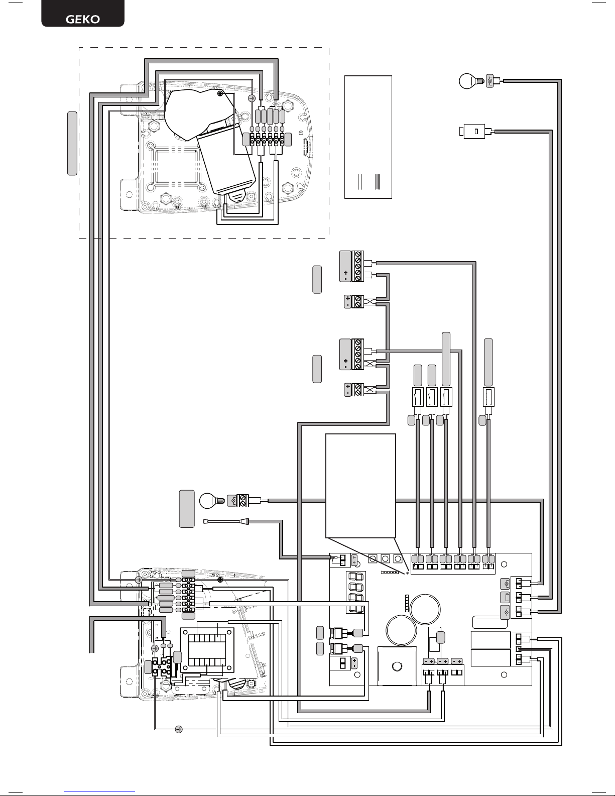
Execute the wiring following the directions of table 1 and diagrams on page 20.
WARNING To ensure an appropriate level of electrical safety always keep the 230V power supply cables apart (minimum 4mm in the
open or 1 mm through insulation) from low voltage cables (motors power supply, controls, electric locks, aerial and auxiliary circuits
power supply), and fasten the latter with appropriate clamps near the terminal boards.
WARNING Connect to the power supply 230 V ~± 10% 50 Hz through a multi pole switch or a different device that can ensure multi pole
disconnection from the power supply, with a contact opening of 3 mm.
WARNING To connect the encoder to the control panel, use only a dedicated cable 3x0,22mm2.
Table 1 “terminal board connections”
1-2 +24 V power supply output for auxiliary devices 200mA
3-4 22 V ~ transformer power supply input
5-6 24 V battery power supply or photovoltaic accumulator Green Energy input (follow carefully polarity indications).
7-8 Operator 1 output
9Connection of motors metallic parts
10-11 Operator 2 output (if present)
12-13 24 V max 15 W output for open gate x warning light (if P052=0), ashing (if P052=1) or courtesy light (if
P052>1)
14-15
14 (-) “Boost” output for electric-lock, max 1 x art. 110 (if P062=0), 24V pulse output, max 5W (if P062=1), step
by step (if P062=2), electro-brake output for not self-locking operators (if P062=3), output for electric-lock
power supply via external relay (if P062=4), output for electro-magnets power supply for barriers (if P062=5)
or temporized output (if P062>5).
15 (+)
16-17 24 V Flashing light output max 15W art. Lumy/24A/S
18-19 18 - N.C. Input 6 STOP. In case of intervention, it stops the movement of both motors during any
operation. If unused, short circuit.
If the installation requires different commands
and / or additional to the standard, you can
congure each input to the required rate.
Refer to Chapter
“Advanced Programming”.
19 - Com
20-21
20 - N.C. Input 5 PHOTO 2. When enabled (see parameter P051 in the table), activation of PHOTO
2 provokes: an inversion of direction (during closing), the arrest of the movement (during
opening), prevent the start (gate closed). If unused, short circuit.
21 - Com
22-23
22 - N.C. Input 4 PHOTO 1. When enabled (see parameter P050 in the table), activation of PHOTO
1 provokes: an inversion of direction (during closing), the arrest of the movement (during
opening), prevent the start (gate closed). If unused, short circuit.
23 - Com
24-25 24 - N.C. Input 3 SAFETY. If activated, it causes the inversion. See P055 and P056 on the parame-
ters table. If unused, short circuit.
25 - Com
26-27 26 - N.O. Input 2 PED. If activated, it opens motor nr. 1 only.
27 - Com
28-29 28 - N.O. Input 1 START. In case of intervention it provokes: the operator opening or closing. It may
operate as “inversion” mode (P049=0) or “step by step” mode (P049=1).
29 - Com
30 Aerial signal input
31 Ground aerial input
32-33 32 (+) DE@NET mains input (unused at the moment)
33 (-)
CON 1 230 V ~ ±10% (50/60 Hz) power supply input
CON 2 Connection of encoder to operator 2 (1-2-3)
CON 3 Connection of power supply to operator 2 + ground (4-5-6)
J5 J9 Encoder selection Jumper:
•A position = operators with encoder (remind to set P029=0)
•B position = operators without encoder (remind to set P029=1)
AB AB

20
7 98 10 11 12 13 14 15 16 17
18
19
20
21
22
23
24
25
26
27
28
29
31 3033 32
2
1
4
3
6
5
ABAB
FLASHWARNING
J5 J9
LOCK
ELECTRIC LOCK
art.110
2 x 1 mm2
2 x 0,5 mm2
2 x 1 mm2
3 x 0,22 mm2
2 x 1,5 mm2
RG58
OPEN GATE WARNING LIGHT
24V 15w
INTERNAL WIRING SET
BY THE FACTORY
EXTERNAL WIRING SET
BY THE INSTALLER
POWER SUPPLY
230V~ 50Hz ±10%
CON1
CON2
CON3
CON2
CON3
* WARNING: If the installation
requires dierent commands and
/ or additional to the standard, you
can congure each input to the
required rate. Refer to Chapter
“Advanced Programming”.
ENC
M1
ENC
M2
F
N
1 x 1,5 mm2
1234 5 6
1
2
345
6
FLASH
LUMY/24A/S
max 15W
N.O.
N.O.
N.C.
SAFETY (Only if needed)
START
PED
TX RX TX RX
COM
N.C.
N.O.
PHOTO 2PHOTO 1
COM
N.O.
COM
N.O.
COM
N.C.
COM
N.C.
COM
N.C.
2 x 0,5 mm2
2 x 0,5 mm2
2 x 0,5 mm2
2 x 0,5 mm2
2 x 0,5 mm2
2 x 0,5 mm2
N.C.
STOP (Only if needed)
COM
N.C.
2 x 0,5 mm2
BLUE
RED
BROWN
WHITE
GREEN
2 x 0,5 mm2
F2
Mot 2 (Only if present)
COM
N.C.
N.O.
F1
BLUE
RED
BROWN
WHITE
GREEN

21
6 STANDARD PROGRAMMING
1 Power Supply
Give power supply, the display shows the following symbols “ ”, “ ”, “ ” and then “- - - -”.
* If the control panel has already been programmed and the power fails or is switched off - once power is returned and a START command
is given, the position reset procedure is performed (see “rESP” in the table “WORKING STATUS MESSAGES” on page 26.
2 Visualisation of inputs and operations-counter status
1. Press the key for 15 seconds;
2. The display will show respectively:
Inputs status (check it’s correct);
Total operations counter (* see P064):
i.g.: = 3x1000* = 3000 operations performed
Maintenance operations-counter (* see P065):
i.g.: = 5*x500 = 2500 operations remaining be-
fore the maintenance intervention request ( = ma-
noeuvres-counter disabled)
3. Hold down the key to display a cyclic 3 options, or rele-
ase the button to exit the parameter.
3 Selection type of operators ! IMPORTANT !
1. Scroll down the parameters with and keys until you visua-
lise P028;
2. Access the parameter by pressing the key;
3. Verify that the value corresponds to d000 (GEKO), otherwise, you
must select it by pressing and keys;
4. Conrm your choice by pressing the key (display returns again
to P028).
4 Selection operating with or without encoder ! IMPORTANT !
Warning: Remember to correctly set the jumpers J5 and J9.
1. Scroll down the parameters with and keys until you visua-
lise P029;
2. Access the parameter by pressing the key;
3. Acting on and keys, set:
- d000=for operators with encoder;
- d001=for operators without encoder;
4. Conrm your choice by pressing the key (display returns again
to P029).

22
5 Selection 1 or 2 operators functioning
1. Scroll down the parameters with and keys until you visua-
lise P030;
2. Access the parameter by pressing the key;
3. Acting on and keys, set:
- d001=for a single motor operating;
- d002=for 2 motors operating;
4. Conrm your choice by pressing the key (display returns again
to P030).
6 Motor stroke learning
1. Scroll down the parameters with and keys until you visualise P003;
2. Access the parameter by pressing the key;
3. When “ ” ashes, continue pressing the key;
4. Release the key when “ ” stops ashing; the learning procedure starts;
5. Wait for the door (or doors in case of using 2 motors) searches and stops on the opening stop and then on the closing stop.
If you want to anticipate the stopping strokes in opening, you can manually intervene by giving an impulse to “Start” button (or
pressing the “OK” on the control panel) simulating the stroke.
6. Once the procedure is ended, the display will show “- - - -“.
WARNING Once you have executed the learning stroke, operate a complete cycle (opening/closing) and then check the manual release
to make sure it is working properly. If it’s to “hard” increase the value of P057 of 1 or more.
7 Transmitters learning
7.1 Transmitters coding selection
1. Scroll down the parameters with and keys until you visualise
P027;
2. Access the parameter by pressing the key;
3. Select the type of transmitter by scrolling and keys:
- d000=x rolling-code (suggested);
- d001=complete rolling-code;
- d002=dip-switch;
4. Conrm by pressing on the key (display shows again P027).
Warning: If you need to vary the type of encoding, and only if other remo-
tes with different encoding are memorized, you need to erase memory
(P004) AFTER you have set the new encoding.

23
7.2 Learning
1. Scroll down the parameters with and
keys until you visualise P005;
2. Conrm by pressing on the key;
3. When the symbol “ ” appears, press on
any key of the transmitter you want to memo-
rize;
4. The display visualizes the number of the trans-
mitter just memorized and then “ ”;
5. Memorize all necessary transmitters repeat-
ing this procedure from step 3;
6. Wait 10 seconds before quitting the memori-
zation mode, display shows now “- - - -“.
Warning: In the case of rolling code remotes,
the receiver can be put into learning mode by
pressing the hidden button on a remote control
previously learned.
Warning: When using personalized transmitters,
after entering P005 the learning of the rst
personalized transmitter is possible only by
pressing its hidden button. Afterwards, only
transmitters personalized with the same
encryption key can be memorized (through the
usual procedure), unless a memory reset is
carried out (P004).
8 Adjustment of operating parameters
If you need to modify the operating parameters (force, speedness
etc..):
1. Scroll down the parameters until you visualize the desire para-
meter (i.g. P032);
2. Access the parameter by pressing the key;
3. By pressing on and keys, set up the desired value;
4. Conrm by pressing on the key (display shows the parameters
previously selected).
For the complete list of the “Operating Parameters” See the
table on page. 29.
9 Programming complete
WARNING At the end of the programming procedure, use the buttons and until the appearance of the symbol “- - - -”, the operator
is now ready again for new manoeuvres.
To perform any “Advanced Programming” operations (cancellation of the remotes, conguration inputs, etc. ..), see on page 24.

24
7 ADVANCED PROGRAMMING
Here are some added programming procedures relating to remotes memory management and advanced conguration of the control
inputs.
1 Deletion of memorized transmitters
1.1 Deletion of all transmitters
1. Scroll down the parameters until you visualize P004;
2. Conrm by pressing on the key;
3. When “ ” is ashing, press the key for a few sec-
onds;
4. Release the key as soon as “ ” stops ashing;
5. All memorized transmitters have been deleted (display
shows again P004).
1.2 How to search and delete a transmitter
1. Scroll down the parameters until you visualize P006;
2. Conrm by pressing on the key;
3. By pressing on and , keys, select the transmitter you
want to delete (eg. );
4. When “ ” ashes, conrm the deletion by pressing
the key for a few seconds;
5. Release the key when appears “ ”;
6. The selected transmitter is deleted (display shows again
P006).
2 Resetting of default parameters
1. Scroll down the parameters until you visualize P007;
2. Conrm by pressing on the key;
3. When “ ” ashes, press the key;
4. Release the key as soon as “ ” stops ashing;
Default parameters for the conguration currently in
use are restored;
5. At the end of the operation display returns to P007.
Warning: After you restore the default parameters, you
must program the control panel again and adjust all ope-
rating parameters, in particular, remember to properly set
the conguration of parameters (P028 - P029 - P030 –
operator conguration).
3 Locking-Unlocking access to programming
By using a “dip-switch” remote (regardless of the type of remotes already memorized) it’s possible to lock-unlock access to the program-
ming of the control panel to avoid tampering. The remote setting is the locking-unlocking code veried by the control board.
3.1 Locking access to programming
1. Scroll through the parameters with the buttons
and until the display shows P008;
2. Access the parameter by pressing the button ;
3. The display shows alternately the writing
to indicate that the control board
is waiting for the transmission of the block code;
4. Within 10 seconds press CH1 on the “TX Master”,
the display shows before returning
to the list of parameters;
5. Access to programming is locked.

25
3.2 Unlocking access to programming
1. Scroll through the parameters with the buttons
and until the display shows P008;
2. Access the parameter by pressing the button ;
3. The display shows alternately the writing
to indicate that the control board
is waiting for the transmission of the unlocking
code;
4. Within 10 sec. press the CH1 of the “TX Master”,
the display shows before returning
to the list of parameters;
5. Access to programming is unlocked.
3.3 Unlocking access to programming and global reset
WARNING! This procedure involves the loss of all stored set-
tings.
The procedure allows the unlocking of the control panel without
having to know its unlocking code.
Following this release, in particular, remember to properly set
the conguration of parameters (P028 - P029 - P030 – operator
conguration). You will also need to repeat the measurement of
impact forces to ensure the installation compliance to standards.
1. Scroll through the parameters with the buttons and until
the display shows P008;
2. Access the parameter by pressing the button ;
3. The display shows alternately the writing ;
4. Press the button , the display shows the ashing writing
;
5. Press the button again and hold for 5 seconds (releasing it be-
fore, the procedure is terminated): The display shows the xed
writing followed by , before returning to the list of
parameters;
6. Access to programming is unlocked.
4 Inputs conguration
Where the installation requires different commands and / or additional to
the standard ones described by plan, you can congure each input for the
operation desired (eg START, PHOTOS, STOP, etc ...).
1. Scroll down the parameters with the and to see that corresponding
to the desired one:
● P017=for INPUT 1;
● P018=for INPUT 2;
● P019=for INPUT 3;
● P020=for INPUT 4;
● P021=for INPUT 5;
● P022=for INPUT 6;
2. Conrm by pressing on the key to get access to the parameter (eg.
P018);
3. Scroll down with the and , keys to set the value corresponding to
the desired operation (refer to table “Input Conguration parameters” on
page 28);
4. Conrm by pressing on the key (display shows again P018).
5. Execute the new connection to the input just recongured.
5 Programming complete
WARNING At the end of the programming procedure, use the buttons and until the appearance of the symbol “- - - -”, the operator
is now ready again for new manoeuvres.

26
8 MESSAGES SHOWN ON THE DISPLAY
WORKING STATUS MESSAGES
Mess. Description
Gate is closed
Gate is opened
Opening under way
Closing under way
While in step-by-step mode, the control board awaits further instructions after a start command
Stop command received
Reset current position: The control unit has just been turned on after a power failure, or the gate has exceeded the maximum number (80) of
inversions allowed without ever getting to the closing stroke, or the maximum number (3 ) of consecutive operations allowed of the anti- cru-
shing device.
Once the control unit has been reset and open command given the gate will start moving at slow speed, until it reaches end of travel.
ERROR MESSAGES
Mess. Description Possible solutions
Error position: The reset position procedure is not suc-
cessful. The control panel is awaiting commands.
- Make sure there are no specic frictions and / or obstacles during the run;
- Give a start pulse to initiate a position reset procedure;
- Verify that the operation is completed successfully, manually helping the run, if ne-
cessary;
- Adjust power and speed settings if necessary.
External photocells and/or safety devices are activated
or out of order. - Make sure that all safety devices and/or photocells installed are working properly.
Possible failure to the control board power circuit. - Disconnect and connect power supply. Give a start impulse, if this error appears
again, replace the control board.
Time-out operators run: The engine/s exceeded the
maximum operating time (4min) without ever stopping.
- Give a start pulse to start the position reset procedure;
- Ensure that this operation is successful.
Time-out obstacle detection: With anti-crushing sensor
disabled, was still detected the presence of an obsta-
cle that prevents movement of the leaf for a period of
10 seconds more.
- Make sure there are no specic frictions and / or obstacles during the run;
- Give a start pulse to initiate a position reset procedure;
- Verify that the operation is completed successfully.
Operators mouvement not detected.
- Make sure that operators and encoders connections are well done.
- Check that jumpers J5 and J9 are well positioned as shown on the electric wiring.
- If this error appears again, replace the control panel.
9 START-UP
The start-up phase is very important to ensure maximum security and compliance to regulations, including all the requirements of EN
12445 standard which establishes the test methods for testing the automation for gates.
DEA System reminds that all installation, maintenance, cleaning or repair operations on any part of the system must be performed
exclusively by qualied personnel who must be responsible of all texts requie by the eventual risk;
9.1 Installation test
The testing operation is essential in order to verify the correct installation of the system. DEA System wants to summarize the proper
testing of all the automation in 4 easy steps:
• Make sure that you comply strictly as described in paragraph 2 “WARNINGS SUMMARY”;
• Test the opening and closing making sure that the movement of the leaf match as expected.
We suggest in this regard to perform various tests to assess the smoothness of the gate and defects in assembly or adjustment;
• Ensure that all safety devices connected work properly;
• Perform the measurement of impact forces in accordance with the standard 12445 to nd the setting that ensures compliance with
the limits set by the standard EN12453.
WARNING Using spare parts not indicated by DEA System and/or incorrect re-assembly can create a risk to people, animals and
property and also damage the product. For this reason, always use only the parts indicated by DEA System and scrupulously follow all
assembly instructions.
9.2 Unlocking and Manual operation
In the event of malfunctions or simple power failure, release the motor (Pic. 9) and perform the operation manually.
The knowledge of the unlocking device is very important because, in times of emergency, lack of speed in operating this device can
cause danger.
WARNING The efcancy and safety of manual operation of the automation is guaranteed by DEA System only if the installation has
been installed correctly and with original accessories.

27
10 MAINTENANCE
Good preventive maintenance and regular inspection ensure
long working life. In the table below you will nd a listo f inspections/
maintenance operations to be programmed and executed periodi-
cally.
Consult the TROUBLE-SHOOTING” table whenever anomalies are
observed in order to nd the solution to the problem and contact
DEA System directly whenever the solution required is not provided.
INTERVENTION TYPE PERIODICITY
cleaning of external surfaces 6 months
checking of screw tightening 6 months
checking of release mechanism operation 6 months
greasing of articulated joint 1 year
TROUBLE-SHOOTING
Description Possible solutions
When the opening command is given, the gate wing fails to
move and the operator’s electric motor fails to start.
The operator is not receiving correct power supply. Check all connections, fuses, and the
power supply cable conditions and replace or repair it if necessary. If the gate does not close
check if the photocells work properly.
When the opening command is given, the motor starts but
the gate leaf fails to move.
Make sure the unlocking system is closed.
Make sure that the electronic device for power adjustment is in good condition.
The operator jerks or is noisy during movement, it stops mi-
dway or else it does not start.
If the leaf of the gate does not move freely, release the operator and readjust the rotation
points.
The power of the gearmotor may be insufcient for the characteristics of the gate’s leaf;
check the choice of model whenever required.
If the plate fastening the operator to the gate bends or is inappropriately fastened, repair it
or reinforce it.
11 PRODUCT DISPOSAL
GEKO consists of materials of various types, some of which can be recycled (electrical cables, plastic, aluminum, etc. ..) while others
must be disposed of (electronic boards and components).
Proceed as follows:
1. Disconnect the power supply;
2. Disconnect and disassemble all the accessories connected. Follow the instructions in reverse to that described in the section “Installa-
tion”;
3. Remove the electronic components;
4. Sorting and disposing of the materials exactly as per the regulations in the country of sale.
WARNING In line with EU Directive 2002/96/EC for waste electrical and electronic equipment (WEEE), this electrical product must
not be disposed of as unsorted municipal waste. Please dispose of this product by returning it to your local municipal collection
point for recycling.

28
PAR. PROCEDURE SETTABLE VALUES
PROGRAMMING PROCEDURES
Positioning of operator 1
Positioning of operator 2
Memorization of the motors’ stroke
Deletion of transmitters
Transmitters memorizing
Search and deletion of a transmitter
Loading of standard parameters: the list is up dated with factory settings
Lock access to programming
How to learn connected DE@NET devices (unused at the moment)
Unused parameter
Unused parameter
Unused parameter
Unused parameter
Unused parameter
Unused parameter
PAR. SETTABLE VALUES SETTABLE VALUES
DEFAULT VALUES
(for different standards of
installation)
TYPE
01
INPUTS CONFIGURATION PARAMETERS
INPUT_3 selectioning input type • 000: IN3 type=free contact
• 001: IN3 type=constant resistance 8K2
INPUT_1 operating selection • 000: NONE (unused parameter)
• 001: START (start)
• 002: PED. (pedestrian)
• 003: OPEN (separated open)
• 004: CLOSE (separated close)
• 005: OPEN_PM (man present open)
• 006: CLOSE_PM (man present close)
• 007: ELOCK-IN (electric-lock activation. See P062)
• 008: PHOTO 1 (photocell 1)
• 009: PHOTO 2 (photocell 2)
• 010: SAFETY 1 (safety rib 1)
• 011: STOP (lock)
• 012: FCA1 (opening limit switches Mot1)
• 013: FCA2 (opening limit switchtes Mot2)
• 014: FCC1 (closing limit switches Mot1)
• 015: FCC2 (closing limit switches Mot2)
• 016: SAFETY 2 (safety rib 2)
IN1
INPUT_2 operating selection IN2
INPUT_3 operating selection IN3
INPUT_4 operating selection IN4
INPUT_5 operating selection IN5
INPUT_6 operating selection IN6

29
TYPE
01
INPUTS CONFIGURATION
PARAMETERS
Allocation of CHANNEL 1 of remotes • 000: NONE (unused parameter)
• 001: START (start)
• 002: PEDESTRIAN (pedestrian)
• 003: OPEN (separated open)
• 004: CLOSED (separated close)
• 005: OPEN_PM (man present open)
• 006: CLOSED_PM (man present close)
• 007: ELOCK-IN (electric-lock activation. See P062)
CH1
Allocation of CHANNEL 2 of remotes CH2
Allocation of CHANNEL 3 of remotes CH3
Allocation of CHANNEL 4 of remotes CH4
Selection of type of remotes
• 000: HCS x-code
• 001: HCS rolling-code
• 002: Dip-switch
OPERATORS
CONFIGURATION PARAMETERS
Selection type of operators
• 000: GEKO
• 001: LOOK - MAC (Unused)
• 002: GHOST 100/200 (Unused)
• 003: 500 - 502 (Unused)
Selected work with or without encoders.
CAUTION: Remember to correctly set the jumpers J5 and J9 (see table 1)
WARNING: J5, J9 and P029 must be set correctly before performing the procedure for programming
• 000: motors with encoder
• 001: engines without encoder
Selectioning operators number • 001: one operator
• 002: two operators
OPERATING PARAMETERS
Operators speed adjustment during slow-down while opening 15%tot........................100%tot
Operators speed adjustment during the stroke while opening 15%tot........................100%tot
Operators speed adjustment during the stroke while closing 15%tot........................100%tot
Operators speed adjustment during slow-down while closing 15%tot........................100%tot
Slow down duration adjustment while opening 0%tot............................80%to
Slow down duration adjustment while closing 0%tot............................80%to
Operator 1 force adjustment while opening (if = 100% obstacle detection deactivated) 15%tot…...........................100%tot
Operator n.1 force adjustment while closing (if = 100% obstacle detection deactivated) 15%tot…...........................100%tot
Operator n.2 force adjustment while opening (if = 100% obstacle detection deactivated) 15%tot…...........................100%tot
Operator n.2 force adjustment while closing (if = 100% obstacle detection deactivated) 15%tot…...........................100%tot
Automatic closing times adjustment (if = 0 automatic closing deactivated) 0sec...................................255sec
Pedestrian automatic closing time adjustment (se = 0 pedestrian automatic closing deactivated) 0sec...................................255sec
Pedestrian stroke duration adjustment 5%tot…...........................100%tot
Pre-ashing time adjustment 0sec…….10sec
Adjustment of phase displacement time while opening 0sec……………30sec
Adjustment of phase displacement time while closing 0sec……………30sec
Collectivity function: if it is activated it deactivates both opening and closing inputs for the whole duration of automatic opening
and closing
• 000: “collectivity function” deactivated
• 001: “collectivity function” activated
Ram blow function: it pushes the motors closed for one second before each opening movement, so as to ease the electric-lock
release
• 000: “ram blow” deactivated
• 001: “ram blow function” activated

30
TYPE
01
OPERATING PARAMETERS
“Reversal” mode selection (during the manoeuvre a command impulse reverse the mouvement) or “step by step” (during the
manoeuvre a command impulse stops the mouvement). A next impulse restart the operator to the opposite direction.
• 000: “reversal function”
• 001: “step by step function”
PHOTO 1 PHOTO input functioning: If=0: photocell enabled while closing and starting when the gate is stopped; if=1 photocells
are always enabled; if=2 photocells are enabled while closing only. When enabled, its activation provokes: the
inversion (while closing), the stop (while opening) and prevent the starting (when gate is closed).
If=3-4-5, the operation is the same as the values 0-1-2 but with “close immediately” enabled: in any case, during
the opening and/or the pause time, removal of a possible obstacle causes the gate automatically closes after a
xed delay of 5 sec.
• 000: photocell enabled while closing and when gate is stopped
• 001: photocells always enabled
• 002: photocells enabled only while closing
• 003: as 000 but with “close immediately” enabled
• 004: as 001 but with “close immediately” enabled
• 005: As 002 but with “close immediately” enabled
PHOTO 2
Operation mode selection of the warning light output:
If = 0 “warning light” (output always ON when the gate is open, OFF after a closing operation),
If = 1 “ashing warning light” (slow intermittent output during opening and fast while closing, always ON at gate opened, always
OFF at the end of a closing operation only),
If> 1 “courtesy light” (output ON during each movement, OFF when the motor stops, after the setting delay)
• 000: “x warning light”
• 001: “ashing warning light”
• >001 : “courtesy light” off delay
(2sec………………255sec)
Searches for end of stroke while opening too: when activated, operators stop only at their arrival et the end of stroke, also while
opening.
Warning: During the emergency operation (rESP), the motor executes the rst maneuver while opening. In addition, if any limit
switches, the parameter is forced to 1.
• 000: Stop when opening on a memorized point
• 001: Stop when opening on the end of stroke
“soft start” function: motors accelerate gradually until they reach the set speed, avoiding sudden departures
• 000: “soft start” deactivated
• 001: “soft start” activated
• 002: “long soft start” activated
Adjust the inversion on obstacle period (detected by internal anti-crushing sensor or by the safety input when activated): If = 0
it makes a complete inversion, if> 0 indicates the duration (in seconds) of the run, after inversion resulting from detection of an
obstacle during the opening.
• 000: complete reversal on obstacle
• >000: duration of reversal on obstacle
(1sec……………..10sec)
Adjust the inversion on obstacle period (detected by internal anti-crushing sensor or by the safety input when activated): If = 0
it makes a complete inversion, if> 0 indicates the duration (in seconds) of the run, after inversion resulting from detection of an
obstacle during the closing.
• 000: complete reversal on obstacle
• >000: duration of reversal on obstacle
(1sec……………..10sec)
Facilitation manual release: If≠0, after detecting the locking stop, the engine reverses for a brief time to release the pressure on
it, and thus facilitate the manual release. The set value shows the length of the inversion. If=0 function disabled
• 000: facilitating release disabled
• >000: facilitation activated with release time equal to:
(1x25ms……20x25ms)
Adjustment of the opening stroke margin: it adjusts the duration of the last part of the stroke during which an obstacle is
interpreted as a stroke, blocking the motor without performing the inversion.
For motors with encoders, the set value indicates the number of revolutions of the rotor; while for motors without encoder, the
value is expressed in% of the maximum stroke.
Warning: for motors without encoder, if P035 (duration slow-down while opening) is >10%, it forces the stroke detection margin
so that it’s the same than the slow-down.
1..................255 (motors with encoder)
0%…............100% (motors without encoder)
Adjustment of the closing stroke margin: it adjusts the duration of the last part of the stroke during which an obstacle is interpreted
as a stroke, blocking the motor without performing the inversion.
For motors with encoders, the set value indicates the number of revolutions of the rotor; while for motors without encoder, the
value is expressed in% of the maximum stroke.
Warning: for motors without encoder, if P036 (duration slow-down while closing) is >10%, it forces the stroke detection margin so
that it’s the same than the slow-down.
1..................255 (motors with encoder)
0%…............100% (motors without encoder)
Operators force adjustment at stroke arrival - If = 0, setting off (the force value on the stroke is calculated automatically) - If ≠ 0,
indicates the value (expressed in% of the max value ) of the force exerted on the stroke. 0%tot…...........................100%tot
“Energy saving” mode: If=1 after 10sec of inactivity, the control panel turns the 24V outputs and the display off that will be turned
on at rst command received (use recommended battery-powered and / or solar panel).
• 000: “Energy saving” not active
• 001: “Energy saving” active

31
TYPE
01
OPERATING PARAMETERS
Electric-lock output operating: If=0 “boost” output for electric-lock art.110 power supply, If=1 24V output controlled by the ELOCK_
IN input as pulsed mode,If=2 24V output controlled by the ELOCK_IN input as step-by-step mode, If=3 electro-brake output for
not self-locking operators, If=4 24V output for electric-lock power supply via an external relay, If=5 24V output for electro-magnets
power supply for barriers, If>5 24V output controlled by the ELOCK_IN input as temporized mode (the set value indicates the
switch-off delay in seconds).
• 000: “Boost” output for electric-lock art.110 power supply
• 001: “24V pulse output max 5W
• 002: “24V step-by-step output max 5W
• 003: “Electro-brake output for not self-locking operators
• 004: “Output for electric-lock power supply via an external relay
• 005: “output for electro-magnets power supply for barriers
• >005: “24V temporized output max 5W
(6sec………………255sec)
Run direction inversion: If=1 automatically reverses the outputs open/close of the operators and any opening/closing limit
switches inputs, avoiding having to manual change the wiring when installing the operator in an inverted position.
• 000: “Standard installation”
• 001: “Inverted installation”
Multiplier operations-counter: Multiply the number of operations after which the total operations-counter will be updated.
To view the values, refer to the section “Visualisation of inputs and operations-counter status”.
• 000: “x100
• 001: “x1000
• 002: “x10000
• 003: “x100000
Maintenance Operations-counter: if = 0 reset the counter and disables the intervention request , if> 0 indicates the number
of operations (x 500) to be made before the control panel executes a 4 second additional pre-ash to indicate the need of
maintenance.
i.g.: If P065 = 050, operations number = 50x500 = 25000 operations
Warning: Before you set a new value of the counter-manoeuvres maintenance, the same must be reset by setting P065= 0 and
only later P065 = “new value”.
• 000: “Request Maintenance disabled
• >000: “Number of operations (x 500) for required maintenance
(1...................................255)
Selection of operating ashing light output: If=0 intermittent ashing light output;
If=1 Fixed ashing light output (for ashing lights with intermittent interior circuits).
• 000: “intermittent ashing light output
• 001: “xed ashing light output
SAFETY 1 Operation of the SFT input: if = 0 safety edge always enabled, if = 1 safety edge enabled only while closing, if = 2
safety edge enabled only while closing and before any movement, if = 3 safety edge enabled only when opening, if
= 4 safety edge enabled only while opening and before any movement; as for the obstacle detection with internal
anti-crushing sensor, also the activation of the inputs SFT1 and SFT2 causes the complete or partial reversal as set
by P055 (duration of inversion on obstacles while opening, and P056 (duration of reversal on obstacle while closing)
• 000: “safety edge always enabled
• 001: “safety edge enabled only while closing
• 002: “safety edge enabled only while closing and before any movement
• 003: “safety edge enabled only when opening
• 004: “safety edge enabled only while opening and before any movement
SAFETY 2
Delay on limit switch detection: the operation is stopped after 1,5 sec from limit switch detection. When during this delay a stop
is detected, the operator is suddenly stopped
• 000: “limit switch delay disabled
• 001: “limit switch delay enabled
Adjustment of acceleration durability
Warning: if soft start is activated, the acceleration is deactivated indipendently from P070 value.
• 000: “acceleration deactivated (it runs an acceleration of minimum durability,
almost imperceptible)
• 00X: “adjusts the acceleration durability at 1,5 sec (X*6 ms)
Unused parameter
Unused parameter
Unused parameter
Unused parameter
Unused parameter

32

Exclusive Australian Distributor
Customer Service (03) 9364 8288
See downee.com.au for your state office
Tech Support 1800 241 733 techsupport@downee.com.au
downee.com.au
deasystem.com
Other manuals for SWINGER
1
Table of contents
Other Dea Gate Opener manuals

Dea
Dea WING 302 Series Instruction manual

Dea
Dea ghost 200 User manual

Dea
Dea REV Series Product manual

Dea
Dea 224RR Product manual

Dea
Dea MAC STING Product manual

Dea
Dea REV Product manual

Dea
Dea MAC Product manual

Dea
Dea LIVI N Series Product manual

Dea
Dea LOOK User manual

Dea
Dea Look Series Product manual
Popular Gate Opener manuals by other brands

Reisinger
Reisinger S 3000 operating instructions

WALKY
WALKY WL1024 quick start guide

RAMSET
RAMSET JET instruction manual

Letron Auto Gates
Letron Auto Gates SL600 User & installation manual

Erreka
Erreka BUL BL33 Quick installation and programming guide

Comunello Automation
Comunello Automation ABACUS 220 Installation and user manual