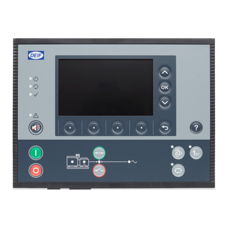
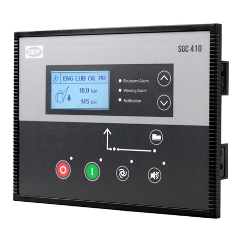
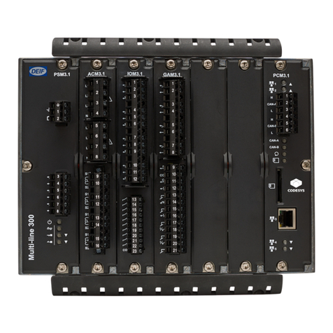
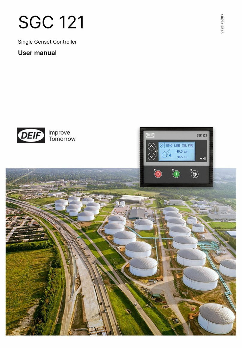
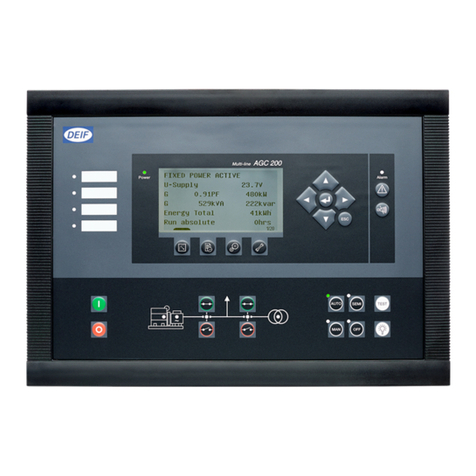
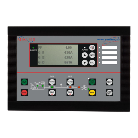
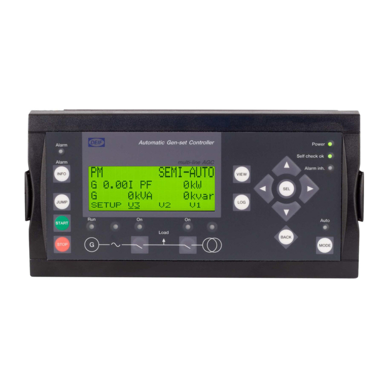
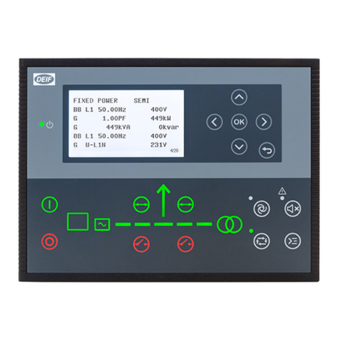
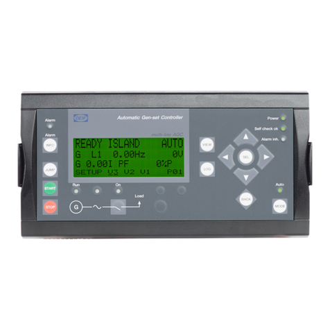
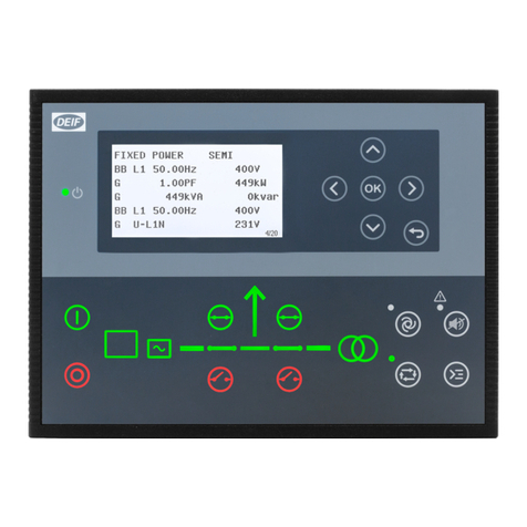
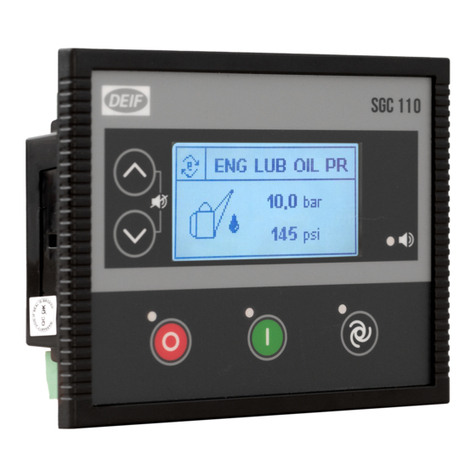
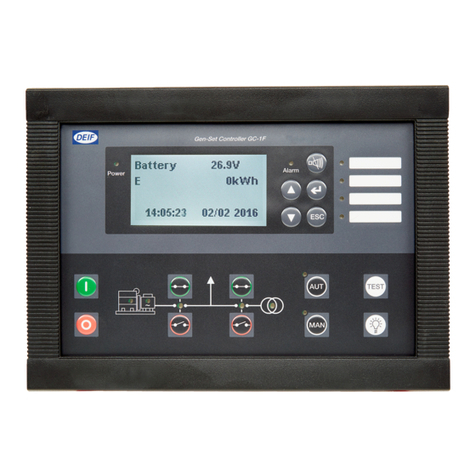
Deif SGC 120 User manual

User manual
Single Genset Controller
SGC 120/121
DEIF A/S · Frisenborgvej 33 · DK-7800 Skive · Tel.: +45 9614 9614 · Fax: +45 9614 9615 · [email protected] · www.deif.com
Document no.: 4189341226A

1. Introduction
1.1 About SGC 120/121................................................................................................................................................................................................................... 4
1.2 Key functions............................................................................................................................................................................................................................... 4
1.3 Product overview....................................................................................................................................................................................................................... 4
1.4 Passwords..................................................................................................................................................................................................................................... 5
1.5 Overview of controller buttons...........................................................................................................................................................................................6
1.6 Legal information.......................................................................................................................................................................................................................7
2. Safety instructions
2.1 General safety instructions.................................................................................................................................................................................................. 8
2.2 Electrical safety...........................................................................................................................................................................................................................8
2.3 In operation safety.....................................................................................................................................................................................................................8
3. Technical specifications
3.1 Terminals........................................................................................................................................................................................................................................ 9
3.2 Power supply................................................................................................................................................................................................................................9
3.3 Genset voltage and frequency measurements....................................................................................................................................................... 10
3.4 Genset current measurements........................................................................................................................................................................................ 10
3.5 Mains voltage and frequency measurement............................................................................................................................................................ 10
3.6 Digital inputs.............................................................................................................................................................................................................................. 11
3.7 Analogue resistive sensor inputs...................................................................................................................................................................................11
3.8 Analogue inputs used as digital inputs...................................................................................................................................................................... 12
3.9 Analogue voltage/current input.......................................................................................................................................................................................12
3.10 Magnetic pick-up (MPU) input........................................................................................................................................................................................13
3.11 Digital outputs........................................................................................................................................................................................................................ 13
3.12 Rotary actuator outputs (SGC 121 only)..................................................................................................................................................................13
3.13 D+ Charger alternator.........................................................................................................................................................................................................14
3.14 Sensor common point........................................................................................................................................................................................................14
3.15 Communication ports.........................................................................................................................................................................................................14
4. Installation
4.1 Dimensions.................................................................................................................................................................................................................................15
4.2 Mounting in panel....................................................................................................................................................................................................................15
4.3 Terminal details........................................................................................................................................................................................................................ 16
4.4 Typical wiring diagrams.......................................................................................................................................................................................................18
5. Monitoring mode
5.1 Monitoring mode......................................................................................................................................................................................................................20
6. Configuration mode
6.1 Configuration mode............................................................................................................................................................................................................... 22
6.2 Configurable parameters.................................................................................................................................................................................................... 22
6.2.1 Configurable parameters..............................................................................................................................................................................................22
6.2.2 Module..................................................................................................................................................................................................................................23
6.2.3 Digital inputs...................................................................................................................................................................................................................... 24
6.2.4 Analogue inputs................................................................................................................................................................................................................25
6.2.5 Outputs.................................................................................................................................................................................................................................28
6.2.6 Timers...................................................................................................................................................................................................................................28
6.2.7 Generator............................................................................................................................................................................................................................29
6.2.8 Mains.................................................................................................................................................................................................................................... 31
6.2.9 Engine.................................................................................................................................................................................................................................. 32
6.2.10 Maintenance....................................................................................................................................................................................................................36
USER MANUAL 4189341226A UK Page 2 of 72

6.2.11 Rotary actuator (SGC 121 only)..............................................................................................................................................................................36
6.2.12 Password ID....................................................................................................................................................................................................................38
6.3 Digital input source selection...........................................................................................................................................................................................38
6.4 Digital output source selection........................................................................................................................................................................................38
7. Running modes
7.1 Auto mode...................................................................................................................................................................................................................................41
7.2 Manual mode..............................................................................................................................................................................................................................43
8. Alarms
8.1 Alarms........................................................................................................................................................................................................................................... 44
9. Modbus communication protocol
9.1 About the Modbus communication protocol........................................................................................................................................................... 47
9.2 Modbus connection details................................................................................................................................................................................................47
9.3 Modbus functions................................................................................................................................................................................................................... 47
10. Modbus communication settings
10.1 Modbus communication settings................................................................................................................................................................................ 48
10.2 Register map (function code 03).................................................................................................................................................................................. 49
10.3 Register map (function code 16).................................................................................................................................................................................. 55
11. Engine communication (SGC 120 only)
11.1 Introduction to engine communication.....................................................................................................................................................................56
11.2 Default settings...................................................................................................................................................................................................................... 56
11.3 Supported engines...............................................................................................................................................................................................................56
11.4 Engine values on the display......................................................................................................................................................................................... 56
11.5 Engine communication settings...................................................................................................................................................................................57
11.6 Generic J1939......................................................................................................................................................................................................................... 58
11.7 Wiring...........................................................................................................................................................................................................................................59
12. CAN communication (SGC 120 only)
12.1 About the CAN communication protocol................................................................................................................................................................ 60
12.2 CAN communication structure......................................................................................................................................................................................60
12.3 CAN packet structure......................................................................................................................................................................................................... 70
13. Troubleshooting
13.1 Troubleshooting.................................................................................................................................................................................................................... 71
USER MANUAL 4189341226A UK Page 3 of 72

1. Introduction
1.1 About SGC 120/121
This document presents information necessary for operating DEIF's SGC 120/121 genset controllers.
SGC 120/121 are modern genset controllers with user friendly HMI and full graphics LCD. The controllers come with a highly
versatile software. Extensive inputs and outputs support a wide variety of industry standard features in diesel/gasoline genset
applications.
SGC 121 includes electronic governing for engines with mechanical fuel systems. With a rotary actuator as add-on for air/fuel
charge control, SGC 121 can perform electronic governing of the engine within ISO 8528 class G3 limits.
The DEIF Smart Connect software offers flexibility to configure each individual input and output for a specific function or application.
All parameters can also be configured on the genset controller.
1.2 Key functions
• Genset controller with configurable inputs:
◦ Five digital inputs
◦ Four analogue inputs (configurable as digital inputs)
• Six digital outputs
• Auto, Manual and Remote start/stop modes for 1-phase and 3-phase gensets
• RPM sensing using frequency and MPU
• Supports Auto exercise mode
• Real time clock-based event logs
• PC connectivity via USB port
• RS-485 and CAN ports
• Configurable fuel theft alarm
• Backlit full graphics display
• Integrated electronic governor controller (SGC 121 only)
1.3 Product overview
Following table gives a brief overview of SGC 120/121 features:
Features Specifications
Digital switch input 5
Analogue resistive inputs 3
Analogue current/voltage input 1
Mains voltage input (AMF) Yes
DG alternator voltage input, D+ charging alternator I/O Yes
DG alternator current input Yes
Engine speed input via MPU Yes
Digital outputs 6
Real Time Clock for event logs and Auto exercise mode Yes
USB I/O port for laptop access Yes
USER MANUAL 4189341226A UK Page 4 of 72

Features Specifications
EEPROM for extended event logs OR regional languages Yes
CANbus Engine Interface Yes
RS-485 Interface for Modbus Yes
DC battery supply voltage (with -32 V reverse protection) 8 to 28 V
Operating temperature range -20 to 65 °C
Protection class with gasket (included) IP65
Warning auto clear enable/disable Yes
Fuel reference selection input Yes
On the fly mode change when engine is healthy/engine off Yes
Analogue 0-5 V input for Speed bias input for E-gov from Load sharing module Yes*
E-gov actuator output Yes*
*Note: SGC 121 only.
1.4 Passwords
The controller is protected from set-up changes with a four digit password.
There are two password levels:
Level Access Factory setting
1 Full access (read and write) 0123
2 Limited access (read) 1234
The passwords can be changed on the controller:
1. Go to Configuration mode.
2. Log on with password level 1.
3. Use the Up and Down buttons to go to Misc Settings, select with the Start button.
4. Use the Up and Down buttons to go to the password to be changed, select with the Start button.
5. Use the Up and Down buttons to choose the first digit for the new password, select with the Start button.
6. Repeat for the next three digits.
7. When all four digits are chosen, the display shows
PASSWORD 1
Password changed
USER MANUAL 4189341226A UK Page 5 of 72

1.5 Overview of controller buttons
1. Menu navigation up button
2. Menu navigation down button
3. Stop/Config button
4. Display
5. Alarm LED
6. Start button
7. Mode selection button
Button functions
In Mode Button input Function
Manual Start Starts the engine
Manual
Auto Enters Auto mode
Stop Stops the engine
Stop (long press) Enters Configuration mode
Down + Stop (long press) Enters Programming mode
Auto Stop Stops the engine and enters Manual mode
Manual
Auto
Configuration
Up
Down Scrolls through the views/parameters
Manual
Auto Up + Down (during Alarm view) Acknowledges and clears the alarm
Configuration Start Selects/saves the parameter
Configuration Up + Down (long press) Enters the Event log page
Configuration Stop (long press) Back to Manual mode
Deep sleep Any Key (for min. 1 s) Back to Manual mode
Event log Up + Down (long press) Back to Configuration mode
Programming Up + Down (long press) Enters Manual mode
USER MANUAL 4189341226A UK Page 6 of 72

1.6 Legal information
Warranty
WARNING
The controller is not to be opened by unauthorised personnel. If the controller is opened anyway, the warranty will be lost.
Disclaimer
DEIF takes no responsibility for installation or operation of the generator set. If there is any doubt about how to install or operate the
engine/generator controlled by the SGC controller, the company responsible for the installation or the operation of the set must be
contacted.
DEIF A/S reserves the right to change any of the contents of this document without prior notice.
The English version of this document always contains the most recent and up-to-date information about the product. DEIF does not
take responsibility for the accuracy of translations, and translations might not be updated at the same time as the English document.
If there is a discrepancy, the English version prevails.
Copyright
© Copyright DEIF A/S 2020. All rights reserved.
USER MANUAL 4189341226A UK Page 7 of 72

2. Safety instructions
2.1 General safety instructions
This document includes important instructions that should be followed during installation and maintenance of the controller.
Installation and maintenance must only be carried out by authorised personnel, and always in accordance with all applicable state
and local electrical codes. Efficient and safe operation of the controller can be acquired only if the equipment is correctly operated,
configured and maintained.
The following notations found in this document can indicate potentially hazardous conditions to the operator, service personnel or
the equipment.
NOTE Highlights an essential element of a procedure to ensure correctness.
CAUTION
Indicates a procedure or practice, which could result in damage or destruction of equipment, if not strictly observed.
WARNING
Indicates a procedure or practice, which could result in injuring personnel or loss of life, if not followed correctly.
2.2 Electrical safety
• Electric shock can cause severe personal injury or death.
• Ensure that the genset is grounded before performing any installation or service.
• Generators produce high electrical voltages, and direct contact with it can cause fatal electrical shock. Prevent contact with
terminals, bare wires, connections, etc., while the generator and related equipment are running. Do not tamper with interlocks.
• To handle the maximum electrical current, the wires used for electrical connections and wirings must be of appropriate size.
2.3 In operation safety
• Before installing the controller, ensure that all power voltage supplies are positively turned off at the source. Disconnect the
generator’s battery cables and remove the panel fuse to prevent accidental start up. Disconnect the cable from the battery post,
indicated by a NEGATIVE, NEG, or (–) first. Reconnect the negative cable last. Failure to do so will result in hazardous and
possibly fatal electrical shock.
• Remove the electric power supply before removing the controller or touching other electrical parts.
• Use extreme caution when working on electrical components. High voltage can cause injury or death.
• With floors of metal or concrete, use rubber insulation mats placed on dry wood platforms when working near the generator or
other electrical equipment.
• Do not wear damp clothing (particularly wet shoes) or allow skin surface to be damp when handling electrical equipment.
• Do not operate any electrical device or wires while standing in water, while barefoot, or while hands or feet are wet. It may result
in severe electrical shock.
• Do not wear jewellery. Jewellery can cause a short circuit within electrical contacts and cause shock or burning.
In case of an accident caused by electric shock, immediately shut down the electrical power source. If this is not possible, try to
release the victim from the live conductor. Avoid direct contact with the victim. Use a non-conducting object (for example a rope or a
wooden stick) to release the victim from the live conductor. If the victim is unconscious, apply first aid and get immediate medical
help.
USER MANUAL 4189341226A UK Page 8 of 72

3. Technical specifications
3.1 Terminals
The SGC 120/121 uses three types of terminal blocks:
Connectors of 3.5 mm pitch Connectors of 5.08 mm pitch Connectors of 10.16 mm pitch
Table 3.1 Terminals
Connector type Pitch Male (on controller)* Female (mating part)* Quantity
4-pin 3.5 mm 5441294 5441430 2
6-pin 3.5 mm 5441317 5449283 1
8-pin 3.5 mm 5441320 5441456 1
10-pin 3.5 mm 5443962 5449306 1
2-pin 5.08 mm 5447353 5441980 1
4-pin 10.16 mm 5474274 5453499 2
*Note: Phoenix (Phoenix Contact (I) Pvt. Ltd.)
3.2 Power supply
Category Specification
Controller terminals 1 (Ground)
2 (Battery or DC+)
Supply voltage range Nominal voltage: 12/24 V DC
Operating range: 8 to 28 V DC
Cranking drop out period 50 ms
Maximum reverse voltage protection -32 V DC
Measurement accuracy (battery voltage) ±1 % full scale
Resolution 0.1 V
Maximum current consumption ~ 200 mA, 12/24 V DC (excluding the current load for the DC and rotary
actuator's outputs)
Standby current consumption LCD backlight off) 124 mA, 12 V DC
123 mA, 24 V DC
Deep sleep current 20 mA, 12/24 V DC
USER MANUAL 4189341226A UK Page 9 of 72

3.3 Genset voltage and frequency measurements
Category Specifications
Controller terminals
27 (Neutral)
28 (L3)
29 (L2)
30 (L1)
Measurement type True RMS
Phase-to-neutral voltage 32 to 300 V AC RMS
Phase-to-phase voltage 32 to 520 V AC RMS
Voltage accuracy ±1 % of full scale for phase-to-neutral
±2 % of full scale for phase-to-phase
Voltage resolution 1 V AC RMS for phase-to-neutral
2 V AC RMS for phase-to-phase
Frequency range 5 to 75 Hz
Frequency accuracy 0.25 % of full scale
Frequency resolution 0.1 Hz
NOTE For single phase applications, it is mandatory to connect the genset phase and neutral cables to the genset controller's
phase L1 and neutral terminals.
3.4 Genset current measurements
Category Specifications
Controller terminals
39 and 40 (for phase L1)
37 and 38 (for phase L2)
35 and 36 (for phase L3)
Measurement type True RMS
Maximum CT secondary current rating Nominal: -/5 A CT
Burden 0.25 VA
Measurement accuracy ±1.4 % of nominal
NOTE Follow the recommended phase sequence while connecting the current transformer (CT)
3.5 Mains voltage and frequency measurement
Category Specifications
Controller terminals
31 (Neutral)
32 (L3)
33 (L2)
34 (L1)
Measurement type True RMS
Phase-to-neutral voltage 32 to 300 V AC RMS
Phase-to-phase voltage 32 to 520 V AC RMS
Voltage accuracy ±2 % of full scale for phase-to-neutral
±2.5 % of full scale for phase-to-phase
USER MANUAL 4189341226A UK Page 10 of 72

Category Specifications
Voltage resolution 1 V AC RMS for phase-to-neutral
2 V AC RMS for phase-to-phase
Frequency range 5 to 75 Hz
Frequency accuracy 0.25 % of full scale
Frequency resolution 0.1 Hz
NOTE For single phase applications, it is mandatory to connect the mains phase and neutral cables to the genset controller's
phase L1 and neutral terminals.
3.6 Digital inputs
Category Specifications
Controller terminals 10, 11, 12, 21, 22
Number of inputs 5
Type Negative sensing (connect to ground for activation)
Software configurable options
Low Lub Oil Pressure (LLOP) Switch, High Water Temperature, and more
(see Controller overview, Configurable parameters in the User manual for
more details).
3.7 Analogue resistive sensor inputs
Category Specifications
Controller terminals
24 (Engine temperature)
25 (Fuel level sensor)
26 (Oil pressure)
Number of inputs 3
Type Ratio-metric sensing
Range 10 to 5000 Ω (terminal 24 and 25)
10 to 1000 Ω (terminal 26)
Open circuit detection Above 1.5 kΩ (terminal 24 and 25)
Above 5.5 kΩ (terminal 26)
Measurement accuracy ±2 % of full scale (up to 1000 Ω)
Connection method Connect the sensor output terminals between the genset controller terminal
and the battery ground terminal
SCP connection
SCP connections for Analogue inputs 1 to 4*:
Battery
Engine body
Sensor
input
Sensor
common
T erminal 41
Terminal 2
Terminal 1
Supply
SGC 1xx series
Analogue
resistive
sensor
USER MANUAL 4189341226A UK Page 11 of 72

*SCP connections for Analogue input 2 used as Fuel level sensor with the reference configured as Battery Negative
Battery
Sensor
input
Sensor
common
Terminal 2
Terminal 1
Supply
Analogue
resistive
sensor
SGC 1xx series
3.8 Analogue inputs used as digital inputs
Analogue inputs can be used as digital inputs when wired as shown.
F1
8-28
V DC
+
-
3.9 Analogue voltage/current input
Category Specifications
Controller terminal 23
Measurement type Analogue voltage/current sensing
Range 0 to 5 V DC
4 to 20 mA
Accuracy ±2 % of full scale voltage
±1.25 % of full scale current
Resolution 0.1 V
0.1 mA
USER MANUAL 4189341226A UK Page 12 of 72

3.10 Magnetic pick-up (MPU) input
Category Specifications
Controller terminal 42
Measurement type Single ended
Frequency range 10 to 10 kHz
Input voltage range 200 mV to 45 V AC RMS
The Magnetic pick-up (MPU) is an inductive sensor fitted on the engine flywheel for the engine speed sensing. The output of the
MPU is a sine-wave signal.
3.11 Digital outputs
Category Specifications
Controller terminals 3, 4, 5, 6, 8, 9
Number of outputs 6
Type DC outputs
Maximum current rating Max. per output: 500 mA
Total max.: 1 A
Software configurable options Start relay, Fuel relay and many more (see Controller overview,
Configurable parameters for more details).
NOTE • Do not connect the starter motor relay and the stop solenoid directly to the controller's output terminals.
• Genset and mains contactor latching relays should be compiled against 4 kVA surge as per IEC-61000-4-5 standard.
3.12 Rotary actuator outputs (SGC 121 only)
Category Specifications
Controller terminal 17, 18. 19 and 20
Type Stepper motor drive
Max. current 1 A
The actuator outputs are used only for the Rotary actuator, if installed. The Rotary actuator is a 4-wire actuator that is used for
creating an electronic governing application in case of a mechanical fuel system engine. In diesel engines, the Rotary actuator's
shaft output gets mechanically connected to the stop lever or the throttle lever of an in-line or rotary fuel injection pump. In case of
petrol or natural gas engines, the Rotary actuator's shaft output gets connected to the throttle/charge control valve.
It is recommended to follow the connection details of the Rotary actuator connector and SGC 121.
USER MANUAL 4189341226A UK Page 13 of 72
3.13 D+ Charger alternator
Category Specifications
Controller terminal 7
Voltage range 0 to VBATT
VBATT = 8 to 28 V DC
Excitation PWM (power limited to 3 W, 12 V/250 mA)
Accuracy ±1 % of full scale
The charge fail is a combined input and output terminal. When the genset starts, the terminal provides controlled power output to
excite the charging alternator. After the excitation is successfully done, the controller reads the charging alternator's output voltage
for monitoring its health. The action for charge fail is configurable.
3.14 Sensor common point
Category Specifications
Controller terminal 41
Range ±2 V
Accuracy ±2 % of full scale
NOTE The sensor common point (SCP) terminal 41 of the controller should be directly connected to an electrically sound point on
the engine body. This point on the engine body should serve as a common reference point for all analogue sensors such as
those for measuring lube oil pressure, engine temperature and fuel level. The electrical cable used for the connection
should not be shared with any other electrical connection. Such a wiring practice is strongly recommended to ensure that
there is negligible potential difference, if any, between the engine body and the controller's SCP terminal, and, predictable
and accurate analogue sensor measurements are always available in a wide variety of field conditions.
3.15 Communication ports
Category Specifications
USB USB 2.0 type B for connection to PC with DEIF Smart Connect software.
RS-485 Serial Port
Half Duplex
Max. Baud Rate 115200
Data connection 2-wire
Termination resistor of 120 Ω between output terminals A and B (internally
mounted)
Common mode operating range and bus pin fault protection up to ±70 V
Maximum distance of line is 200 m
Controller terminals for RS-485 15 and 16
CAN (SGC 120 only)
Baud rate: 250 kbps
Packet size: 8 bytes
Termination resistor of 120 Ω is provided
Controller terminals for CAN (SGC 120 only) 13 and 14
USER MANUAL 4189341226A UK Page 14 of 72
4. Installation
4.1 Dimensions
139.0 (5.47)
114.0 (4.49)
38.3
(1.51)
38.3
(1.51)
Length Height Depth
Controller 139.0 mm (5.47 in) 114.0 mm (4.49 in) 38.3 mm (1.51 in)
Panel cut-out 118.0 mm (4.65 in) 93.0 mm (3.66 in) Tolerance: ± 0.3 mm (0.01 in)
4.2 Mounting in panel
To mount the controller into the panel, use the fixing clips provided along with the controller.
1. Panel surface.
2. Mounting clips.
a. Insert the mounting clips into the slots on the controller.
b. Press the mounting clips backwards until they "click" in place.
c. Turn the screws to tighten the mounting clips (max. torque: 0.19 Nm).
CAUTION
Over-tightening the screw may damage the controller casing.
USER MANUAL 4189341226A UK Page 15 of 72
4.3 Terminal details
Rear view of the controllers with terminal details.
USB
Terminal Text Description Phoenix connector
1 GND Power ground
5441980
2 BATT + Power supply positive
3 DIG OUT A DC output - A
5441430
4 DIG OUT B DC output - B
5 DIG OUT C DC output - C
6 DIG OUT D DC output - D
7 D+ CHG ALT Input for charging alternator control
5441223
8 DIG OUT E DC output - E
9 DIG OUT F DC output - F
10 DIG IN A Input from switch A
11 DIG IN B Input from switch B
5441249
12 DIG IN C Input from switch C
13 CAN H CAN High
14 CAN L CAN Low
15 RS-485 B RS-485 B
16 RS-485 A RS-485 A
USER MANUAL 4189341226A UK Page 16 of 72
Terminal Text Description Phoenix connector
17 GOV_ACT–OUT1 Output for actuator (SGC 121 only)
5447560
18 GOV_ACT–OUT4 Output for actuator (SGC 121 only)
19 GOV_ACT–OUT2 Output for actuator (SGC 121 only)
20 GOV_ACT–OUT3 Output for actuator (SGC 121 only)
21 DIG_IN D Input from switch D
22 DIG_IN E Input from switch E
23
ANLG_I_IN (SGC 120) Analogue input 4 to 20 mA
ANLG_IN (SGC 121) Analogue input 4 to 20 mA/2.5 ±2 V
24 ANLG_IN ENG_TEMP Analogue input from Engine temperature sensor
25 ANLG_IN FUEL_LEVEL Analogue input from Fuel level sensor
26 ANLG_IN LOP Analogue input from Lube oil pressure sensor
27 GEN_V–IN NTRL Voltage input from Generator Neutral
5453499
28 GEN_V–IN L3 Voltage input from Generator phase L3
29 GEN_V–IN L2 Voltage input from Generator phase L2
30 GEN_V–IN L1 Voltage input from Generator phase L1
31 MAINS_V–IN NTRL Voltage input from Mains Neutral
32 MAINS_V–IN L3 Voltage input from Mains phase L3
33 MAINS_V–IN L2 Voltage input from Mains phase L2
34 MAINS_V–IN L1 Voltage input from Mains phase L1
35 GEN_CT–IN L3 1 CT input 1 from Generator phase L3
5441252
36 GEN_CT–IN L3 2 CT input 2 from Generator phase L3
37 GEN_CT–IN L2 1 CT input 1 from Generator phase L2
38 GEN_CT–IN L2 2 CT input 2 from Generator phase L2
39 GEN_CT–IN L1 1 CT input 1 from Generator phase L1
40 GEN_CT–IN L1 2 CT input 2 from Generator phase L1
41 SCP Sensor common point
42 MPU–IN MPU Input
USER MANUAL 4189341226A UK Page 17 of 72

4.4 Typical wiring diagrams
Figure 4.1 SGC 120 typical wiring
120
G
1 2 7 23 24 4125 26
35 37 39 40 10 11 12 21 2236 38 27 28 29 30
13 1442 31 32
31 32 33 34
+ -
‐
+
+
‐
ECU
Engine
body
Tacho
F1
Supply Analogue inputs CAN A
ECU
DC (+)
DC (-)
D+
Input
Input
Sensor
common
Input
Input
Tacho
High
Low
Data + (A)
Data - (B)
RS485
USB
AC voltage
Mains
N
L1
L2
L3
Digital inputs
(configurable)
In
In
In
In
In
AC current CT
AC voltage
genset
L1 (s1)
L1 (s2)
L2 (s1)
L2 (s2)
L3 (s1)
L3 (s2)
N
L1
L2
L3
F4 F5
GB MB
L1
L2
L3
N
L1
L2
L3
N
s2s1
P2P1
s2s1
P2P1
P2P1
s2
s1
345689
Outputs
Output
Output
Output
Output
Output
Output
G
D+
B+
USER MANUAL 4189341226A UK Page 18 of 72

Figure 4.2 SGC 121 typical wiring
G
1 2 7 23 24 4125 26
35 37 39 40 10 11 12 21 2236 38 27 28 29 30
13 14 17
1
18
2
19
3
20
4
42 31 32
31 32 33 34
+ -
‐
+
+
120
ECU
‐
GOV
Tacho
F1
Supply Analogue inputs CAN A
ECU
DC (+)
DC (-)
D+
Input
Input
Input
Input
Tacho
High
Low
E-Gov
Data + (A)
Data - (B)
RS485
USB
AC voltage
Mains
N
L1
L2
L3
Digital inputs
(configurable)
In
In
In
In
In
AC current CT
AC voltage
genset
L1 (s1)
L1 (s2)
L2 (s1)
L2 (s2)
L3 (s1)
L3 (s2)
N
L1
L2
L3
F4 F5
GB MB
L1
L2
L3
N
L1
L2
L3
N
s2s1
P2P1
s2s1
P2P1
P2P1
s2
s1
345689
Outputs
Output
Output
Output
Output
Output
Output
G
D+
B+
Sensor
common
Engine
body
NOTE • Wiring diagrams are examples. Use the application's wiring diagram during installation.
• Genset and mains contactor latching relays should be compiled against 4 kV surge as per IEC-61000-4-5 standard.
• Relay cards used with the controller should be protected against reverse battery voltages.
• Analogue input 2 used for Fuel level sensor can be wired with the reference to Battery Negative, see Specifications,
Analogue resistive sensor inputs.
• Communication ports for CAN ( terminals 13 and 14) and RS-485 (terminals 31 and 32) have built-in 120 Ω resistors.
• If a digital output is connected to a relay, the relay must include freewheeling diodes.
USER MANUAL 4189341226A UK Page 19 of 72

5. Monitoring mode
5.1 Monitoring mode
In Monitoring mode, the display views shift automatically after a pre-defined time. This delay time can be configured in the
configuration menu.
The views can also be changed manually with the Up and Down buttons.
Engine status and operating mode
Manual mode Auto mode Generator voltage
2.1
kVA
Load power1Load apparent power1Load reactive power1
Generator power factor1Generator energy Load current1
Mains status Engine speed Engine run time
Engine battery voltage Engine temperature2Engine lube oil pressure2
USER MANUAL 4189341226A UK Page 20 of 72
Other manuals for SGC 120
1
This manual suits for next models
1
Table of contents
Other Deif Controllers manuals

Deif
Deif AGC 200 Series User manual

Deif
Deif GPC-3 Hydro User manual

Deif
Deif AGC-4 Mk II User manual

Deif
Deif AGC-3 User manual

Deif
Deif AGC 200 Series User manual

Deif
Deif SGC 421 User manual

Deif
Deif CGC 200 User manual

Deif
Deif CGC 200 Installation and operation manual

Deif
Deif ASC Series User manual

Deif
Deif MPC-1 Owner's manual

Deif
Deif AGC 200 Series User manual

Deif
Deif AGC 200 User manual

Deif
Deif GC-1F User manual

Deif
Deif GC-1F User manual

Deif
Deif AGC 100 User manual

Deif
Deif CGC 400 User manual

Deif
Deif AWC 500 Quick start guide

Deif
Deif AGC 200 Series User manual

Deif
Deif Multi-line 2 User manual

Deif
Deif GPC 300 User manual